To model columns for industrial steel structure using TSD
1.
Here are column properties for different types of pedestal members commonly used in construction:
-
Steel Pedestal:
- Material: Steel
- Strength: High tensile strength
- Durability: Resistant to corrosion and weathering
- Load-bearing capacity: Excellent
- Fire resistance: High
- Installation: Welded or bolted connections
- Common applications: High-rise buildings, industrial structures, bridges
-
Concrete Pedestal:
- Material: Reinforced concrete
- Strength: High compressive strength
- Durability: Resistant to weathering and chemicals
- Load-bearing capacity: Excellent
- Fire resistance: High
- Installation: Formwork and casting
- Common applications: Residential buildings, commercial structures, bridges
-
Timber Pedestal:
- Material: Timber (wood)
- Strength: Moderate to high, depending on the species and dimensions
- Durability: Requires protection against moisture, decay, and insects
- Load-bearing capacity: Good, but limited compared to steel or concrete
- Fire resistance: Low to moderate
- Installation: Fasteners, nails, or bolts
- Common applications: Residential buildings, wooden structures, low-rise constructions
-
Composite Pedestal:
- Material: Combination of steel, concrete, or timber with other materials
- Strength: Variable, depends on the composition
- Durability: Varies based on the materials used
- Load-bearing capacity: Customizable based on design requirements
- Fire resistance: Depends on the composition
- Installation: Combination of welding, bolting, or fastening techniques
- Common applications: Specialized structures, architectural features, unique designs
These column properties provide a general overview, but it's essential to consult with structural engineers and adhere to local building codes and regulations when selecting and designing the pedestals.
As for modeling the grids, could you please provide more details about the specific assignment and the type of grids you would like to create
2.
the column properties for steel columns:
- Material: Steel
- Strength: High tensile strength
- Durability: Resistant to corrosion and weathering
- Load-bearing capacity: Excellent
- Fire resistance: High (depending on fire protection measures)
- Installation: Welded or bolted connections
- Shape: Typically H-shaped (e.g., H-beam columns)
- Surface finish: Often painted or galvanized for corrosion protection
- Design flexibility: Can be fabricated to various sizes and lengths
- Maintenance: Relatively low maintenance requirements
Now, let's model the steel columns in the grid created as per Assignment 1. Assuming the grid layout is a two-dimensional grid system, we can represent the steel columns using their coordinates within the grid.
For example, let's say we have a 5x5 grid system, and we want to place steel columns at specific locations:
Grid:
  1   2   3   4   5
1 C1  C2   -  C3   -
2  -    -  C4   -  C5
3  -    -   -   -   -
4 C6   -   -   -   -
5  -    -   -   -   -
In the above grid, "C" represents the steel columns, and the hyphen "-" represents empty spaces without columns. The numbers and letters indicate the coordinates of each cell in the grid.
So, based on the grid layout above, we have the following steel columns placed:
- C1: Located at coordinates (1, 1)
- C2: Located at coordinates (1, 2)
- C3: Located at coordinates (1, 4)
- C4: Located at coordinates (2, 3)
- C5: Located at coordinates (2, 5)
- C6: Located at coordinates (4, 1)
You can modify the grid and adjust the column locations as per your specific assignment requirements.
3.
the properties for beams commonly used in construction:
Beam Properties:
- Material: Typically steel or reinforced concrete
- Strength: High tensile and compressive strength
- Durability: Resistant to weathering and chemical attacks
- Load-bearing capacity: Designed to carry vertical loads, such as dead loads and live loads
- Span: Length of the beam between supports
- Depth: Vertical dimension of the beam, usually measured from the top to the bottom flange
- Width: Horizontal dimension of the beam, typically measured as the distance between the flanges
- Shape: Can be I-shaped (I-beam), H-shaped (H-beam), T-shaped (T-beam), or other custom shapes
- Connections: Joined to columns or other beams through welding or bolted connections
- Fire resistance: Fire protection measures are typically implemented to ensure fire resistance
Now, let's model the primary and secondary beams on the ground floor. Suppose we have a building with a 10x10 grid system, and the ground floor beams are placed as follows:
Grid:
  1   2   3   4   5   6   7   8   9   10
1 PB  PB   -   -   -   -   -   -   -   -
2 PB  PB   -   -   -   -   -   -   -   -
3 SB  SB  SB  SB  SB  SB  SB  SB  SB  SB
4  -   -   -   -   -   -   -   -   -   -
5  -   -   -   -   -   -   -   -   -   -
6  -   -   -   -   -   -   -   -   -   -
7  -   -   -   -   -   -   -   -   -   -
8  -   -   -   -   -   -   -   -   -   -
9  -   -   -   -   -   -   -   -   -   -
10 -   -   -   -   -   -   -   -   -   -
In the above grid, "PB" represents the primary beams, and "SB" represents the secondary beams. The hyphen "-" represents empty spaces without beams. The numbers and letters indicate the coordinates of each cell in the grid.
Based on the grid layout above, we have the following primary and secondary beams placed on the ground floor:
- Primary Beams (PB): Located in rows 1 and 2, spanning the entire length of the grid (columns 1 to 10).
- Secondary Beams (SB): Located in row 3, spanning the columns 1 to 10.
You can modify the grid and adjust the beam locations as per your specific assignment requirements.
ans)
1) open tekla, go to windows select structure window and click on levels.
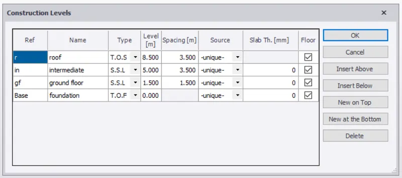
2) enter the levels of model such as foundation, ground floor ,roof along with their spacing and type.
3) now go to grid lines from the ribbon and select grid line and draw a horizontal grid.
4) from the same option ,select parallel quick option and draw other grids as per the plan.
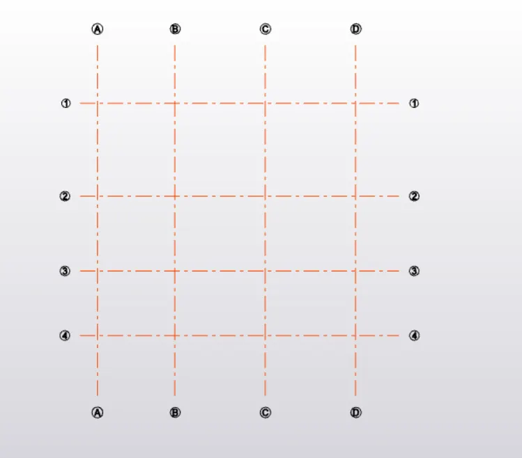
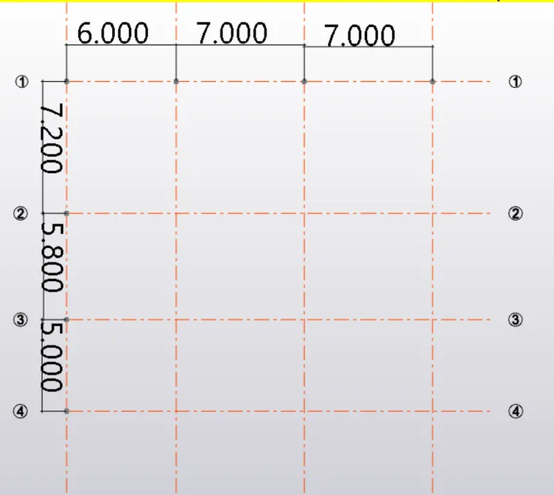
5) now go to manage property sets and click on new, select concrete column.
6) enter its properties such as grade of concrete,major and minor align axis.
7) enter its dimension.
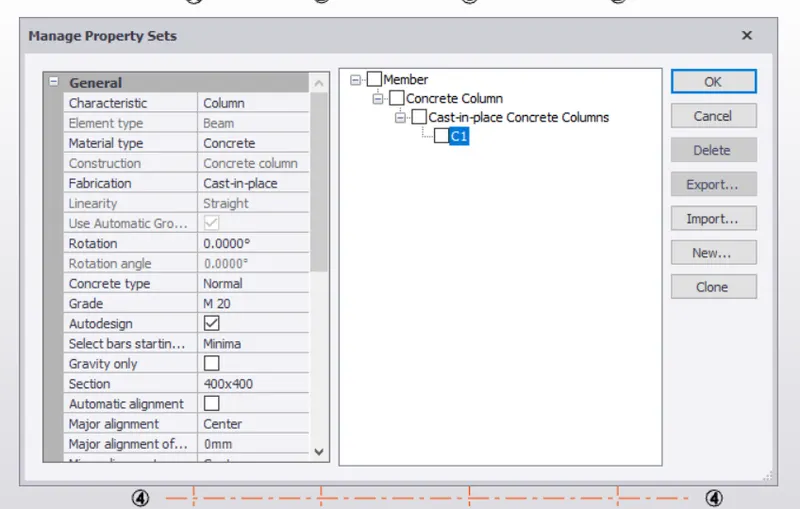
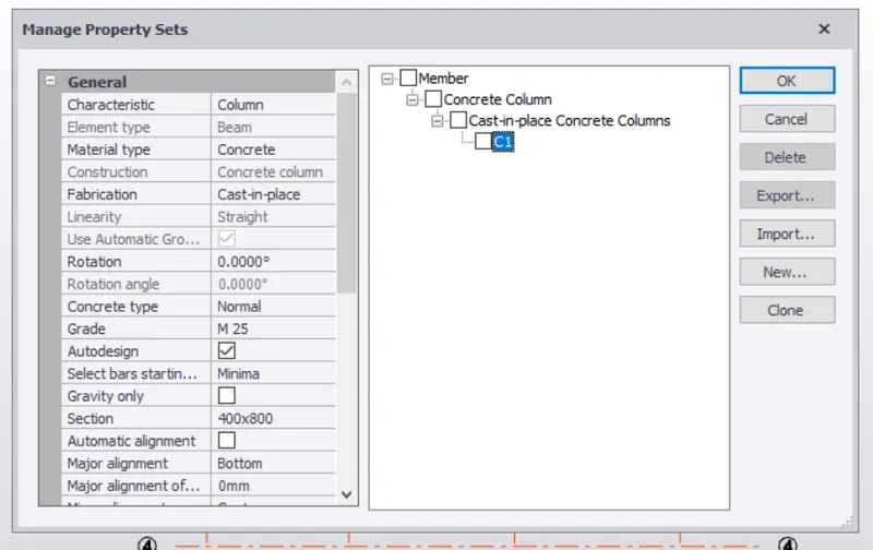
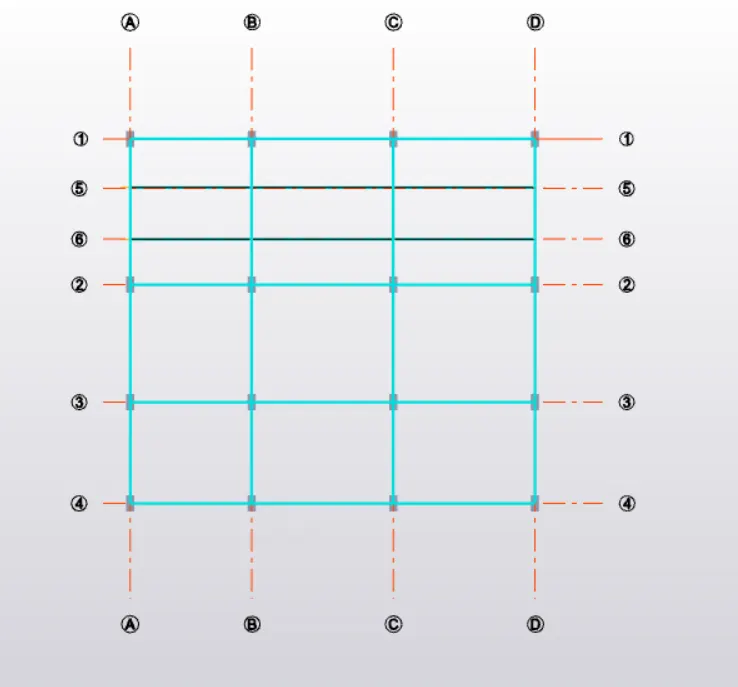
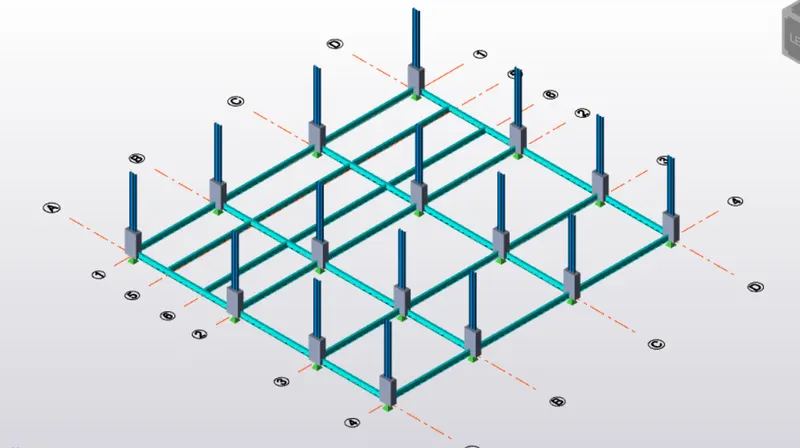
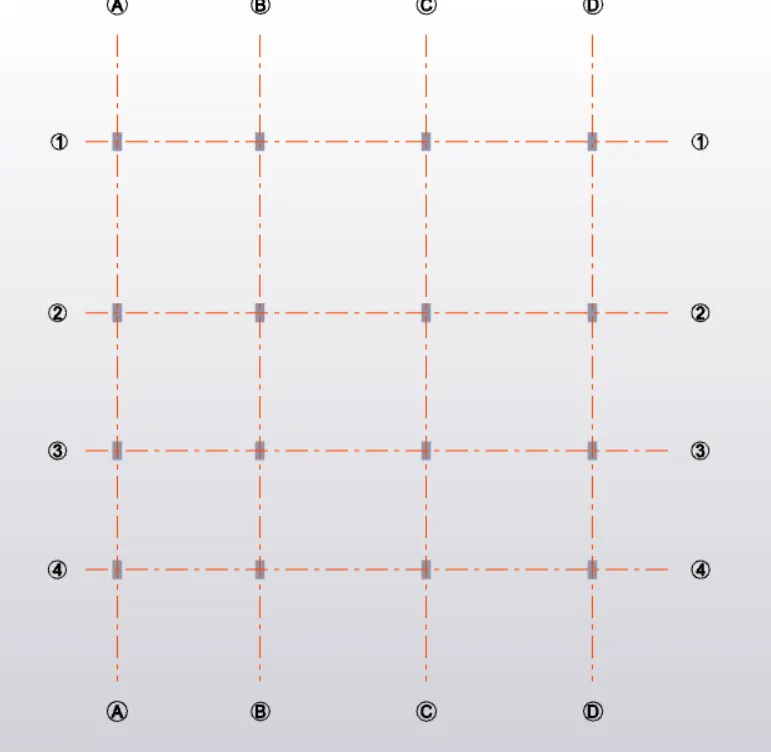
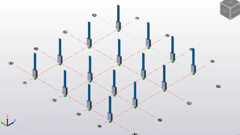
8) now place these columns on the grid intersections as shown below.
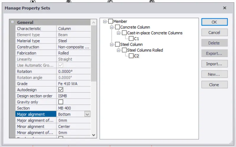
9) similar way enter the properties of steel column such as grade (ISMB 350) major and minor align axis.
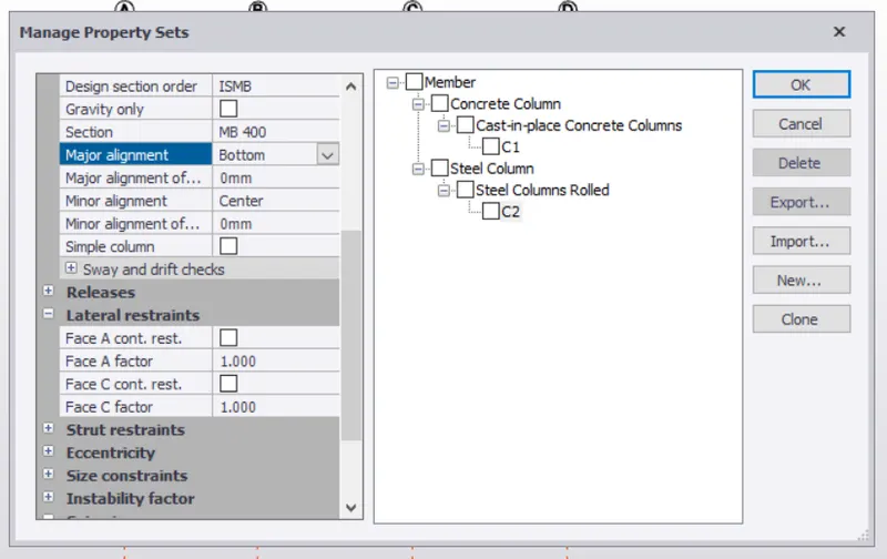
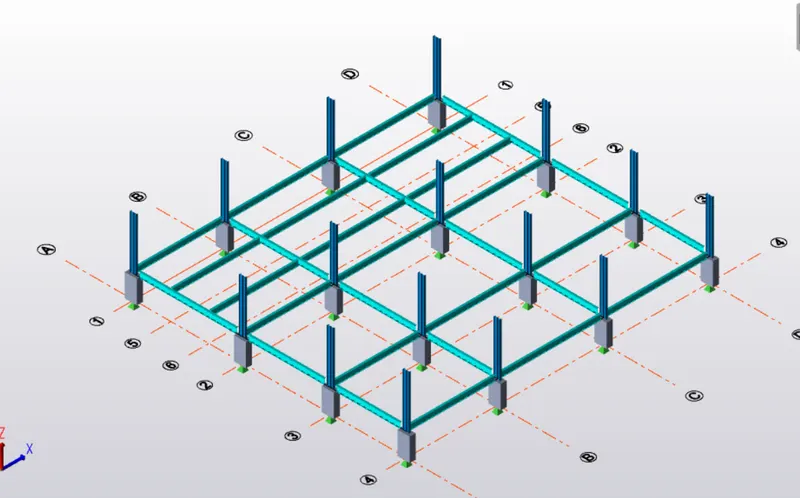
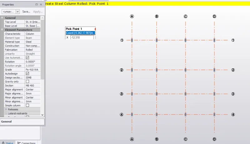
10) now place these columns over concrete columns as shown.
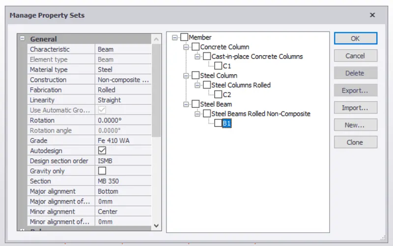
11) similar way define the steel beams B1 with their properties such as grade ,major and minor align axis.
12) now place these beams in the layout provided with columns throughout the layout.
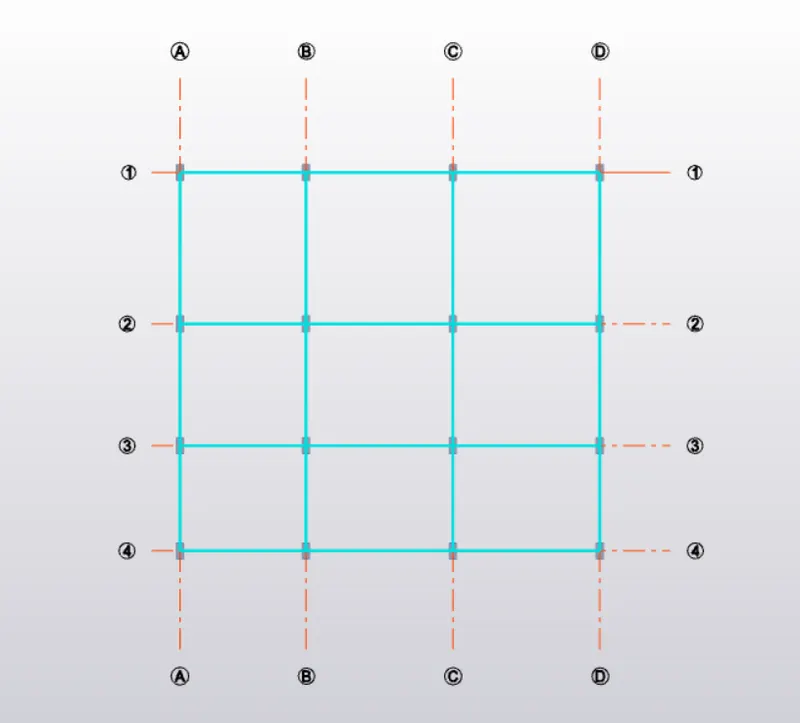
13) here we have placed the beams at base level.
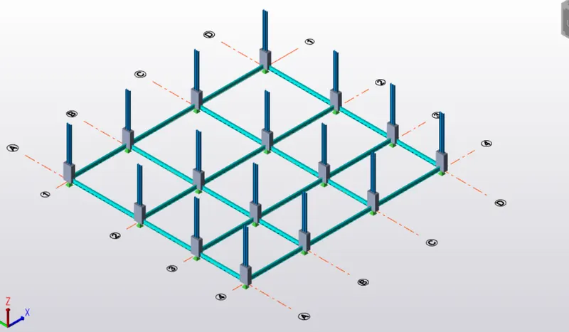
14) now beams have been placed at the ground floor along with the secondary beams in between.