To model columns for industrial steel structure using TSD
1.AIM
To create column properties for different types of pedestal members and model in the grids created as per the assignment 1
Introduction:
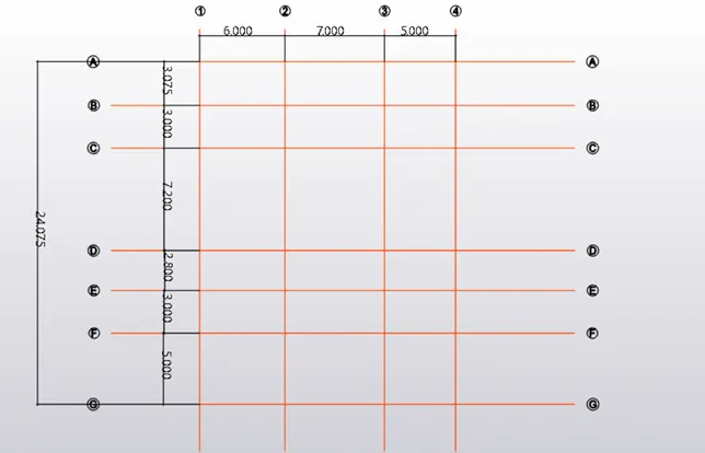
For the above question, let us first assume the pedestal dimension and model it on the grids created as per the previous assignment
Procedure:
- Open the file created in the previous assignment
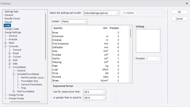
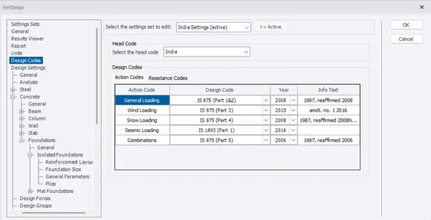
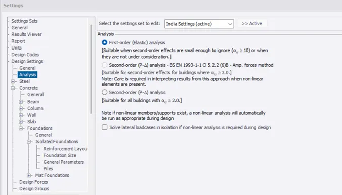
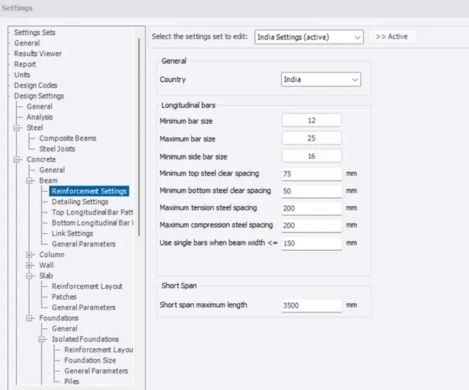
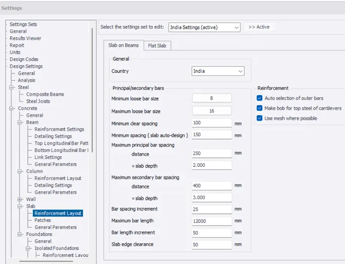
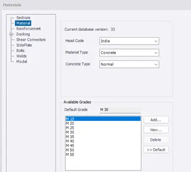
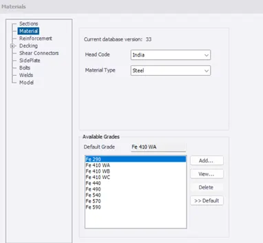
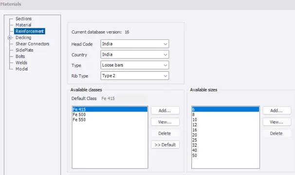
- Since we are going to begin the modelling of the members it is necessary for us to check the settings from Home – Settings as follows
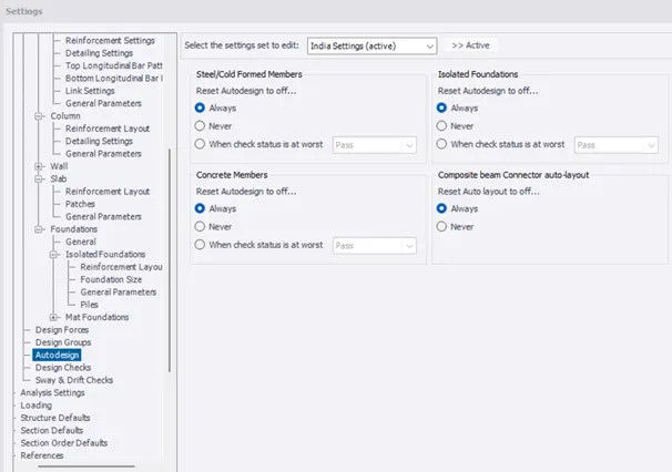
- Also ensure the auto design is off
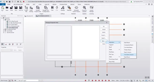
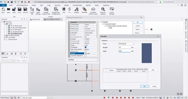
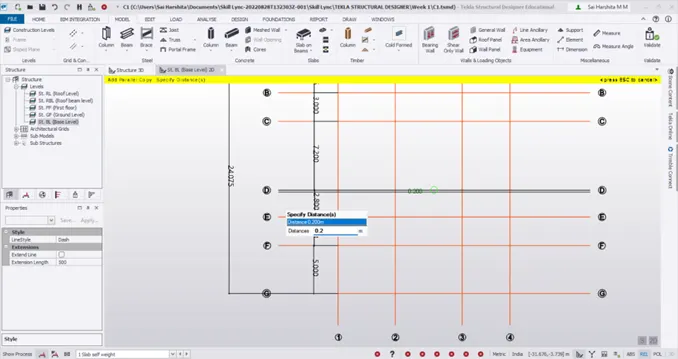
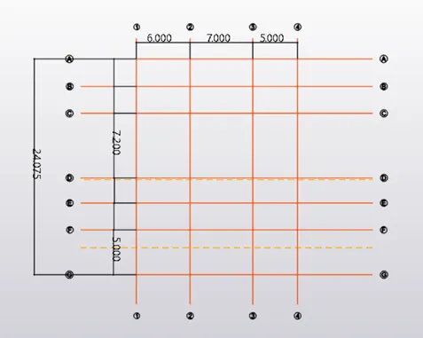
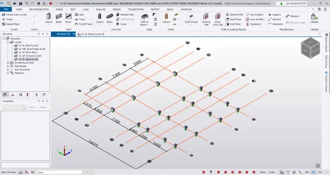
Result:
- The column properties are created by using Manage Property Set
- The construction lines are created wherever needed
- The columns are modelled by using Model – Concrete – Column option
- AIM:
To create column properties for steel columns and model columns in the grid created as per assignment 1.
Introduction:
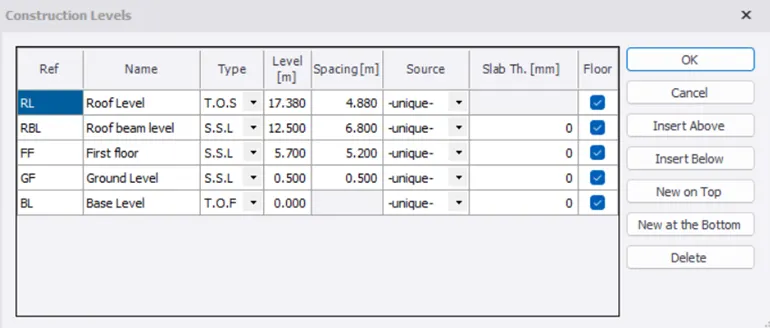
The steel column is used to transfer the loads from the steel beams down to the pedestal. ISMB sections are to be used for steel columns. The steel columns level is from the GF level till the Roof beam level RBL
Procedure:
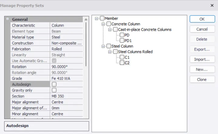
- Go to Home – Manage Property Sets – New – Members – Steel Column
- Go to Section and modify it as ISMB 350
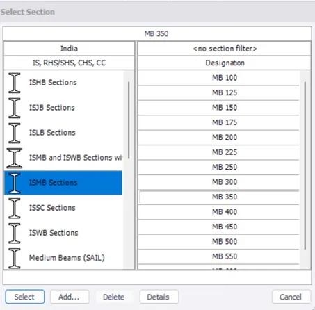
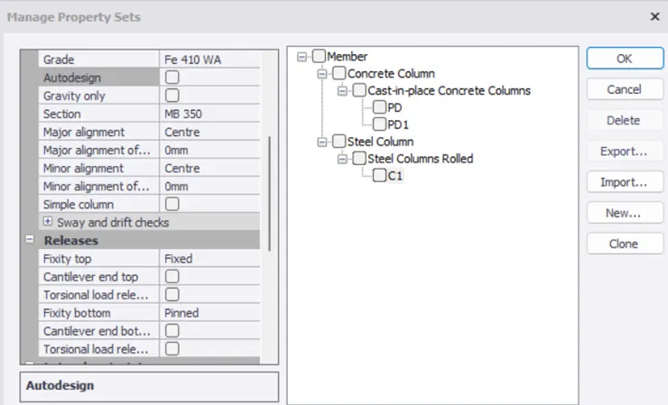
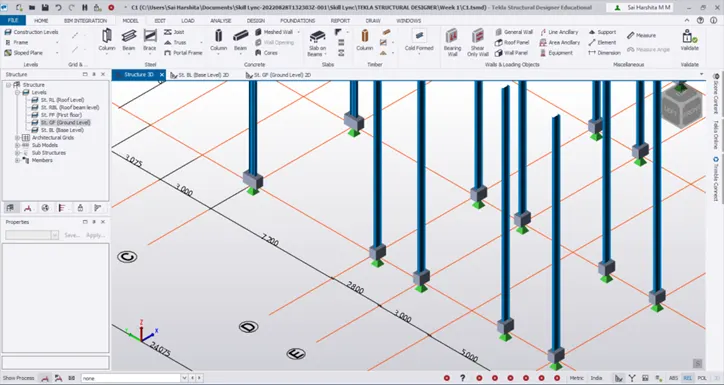
- The steel columns in grid line C are modelled with C1 using Model – Steel – Columns
- Click on the intersecting point of the grid C to place the columns
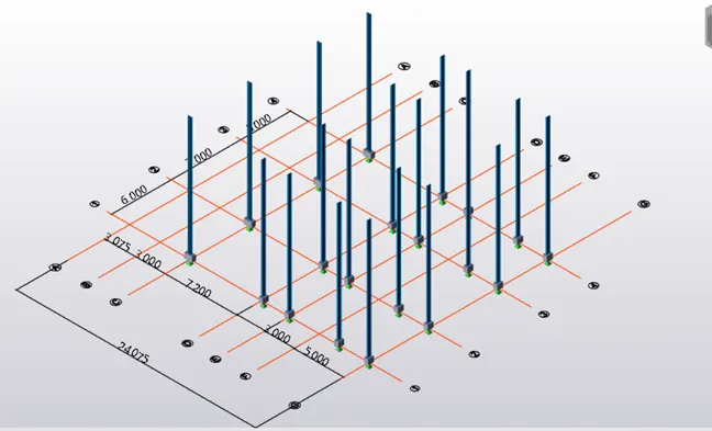
- After placing it could be viewed in 3D also
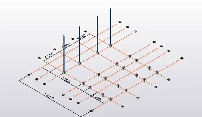
- Another set of columns C2 of ISMB 350 but with rotation as 90 deg is to be modelled for the remaining grids
Result:
- The beam properties are created by using Manage Property Set
- The columns are modelled in the appropriate grids by using Model – Steel – Column option
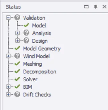
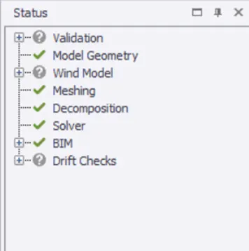
- Validation is done to check for any errors/warnings
- AIM:
To create beam properties and model primary and secondary beams on the ground floor
Introduction:
Primary beams are those which transfer load to the columns. They directly rest on columns
Secondary beams are those which transfer load to another beam necessarily a primary beam. They rest on the primary beams. Secondary beams are provided to break the slab length
The beam properties are first created using Manage Property Set. Then they are modelled in the grids
Procedure:
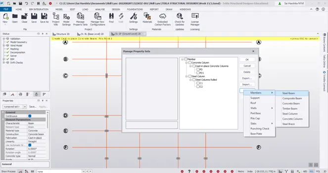
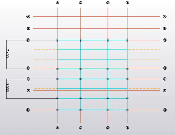
- Model a ISMB 350 beam as a primary beam connecting columns as shown
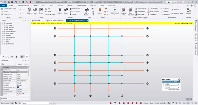
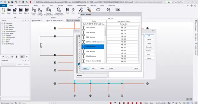
- For modelling secondary beam, construction lines are to be drawn between grids C and D and between E and F1 as shown
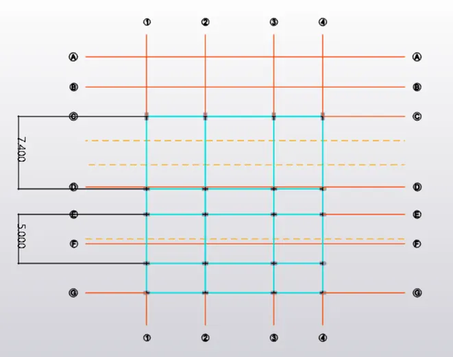
- Now B3 is modelled in those construction lines
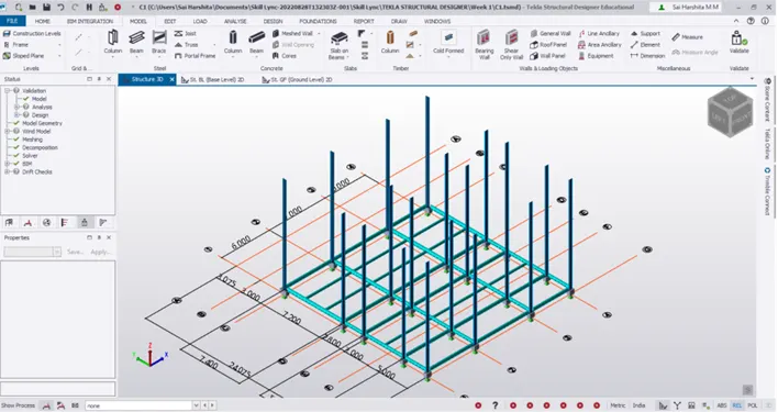
- View it in 3D
Result:
Thus the primary beams B1 and B2 are modelled between columns and secondary beam B3 is modelled between primary beams to break the length of the slab.
- Validate the model once again