To model columns for industrial steel structure using TSD
- Create column properties for different types of pedestal members and model in the grids created as per the assignment 1
AIM:- To create column properties for different types of pedestal members and model in the grids created as per the assignment 1.
INTRODUCTION:- Tekla Structural Design is used for modelling, analysis and design of structural members. Over here, this software used for modelling of concrete pedestal members which is in the base level or foundation level (ie, 0.0m from base level). Pedestal footing transfer all the structural load, ie, slab load, beam load and column load to the foundation and then to soil inorder to keep the structure stable from failing.
PROCEDURE:-
- Open the Tekla Structural Design 2022 software version on the desktop.
- Open the existing file, used for creating construction levels and grid line.
- Since we already constructed construction levels and grid line, we can directly set properties and model members on the grid line.
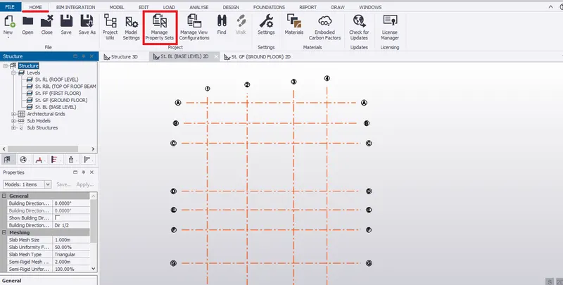
- Firstly, go to HOME, select MANAGE PROPERTY SETS.
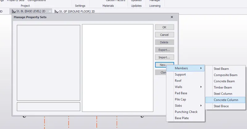
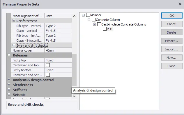
- Click on NEW, select MEMBERS and then CONCRETE COLUMN for pedestal members.
- Rename cast in place concrete column as PD1.
- Set grade of concrete as M25.
- Turn off Auto Design.
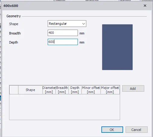
- Select a rectangular section with size of 400mmx 600mm.
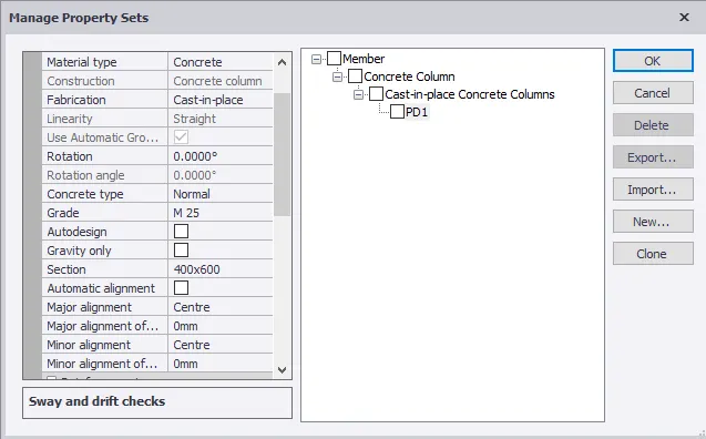
- Select Major Aligement as centre to align pedestal at the centre of the grid line.
- Select Fe 415 grade reinforcement and nominal cover of 40mm for pedestal footing.
- Maximize the Releases by setting both top and bottom fixity as Fixed.
- Then click OK.
- Go to MODEL, select COLUMN under concrete.

- Go to properties window, select PD1 to construct pedestal column on the base level or foundation level .
- Under general tab, set pedestal height from base level to top level(ie, ground floor).
- Check in property window if property assigned to the member as per requirement. Also check the releases.
- In base level of the scene view, pick the point on the intersection of grid lines C and 1 where concrete column/pedestal column is to be placed as discussed in assignment 1.
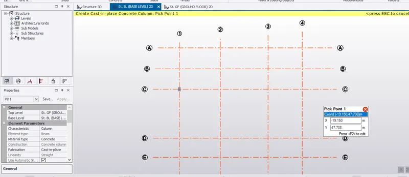
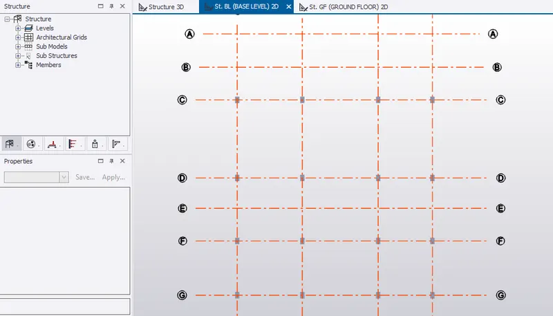
- Similarly, construct pedestal columns on intersection point on the grid line C-2, C-3, C-4.
- Similarly, construct pedestal columns on intersected grid line D, F and G.
- Pick points of pedestal columns are shown below.
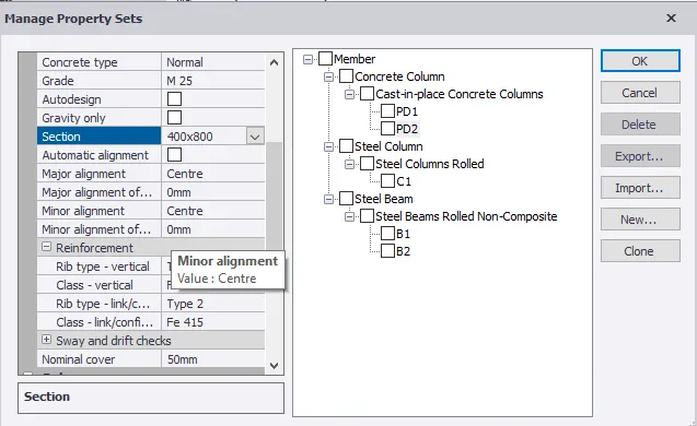
- We can provide larger pedestal member by going to MANAGE PROPERTY SETS
- Click on NEW, select MEMBERS and CONCRETE COLUMN.
- Rename to PD2.
- Set properties of PD2 as M25, reinforcement grade of Fe 415, size of member as (400x800)mm and major alignment to centre. Provide a nominal cover of 50mm.
- Click ok
- Go to scene content, untick the grid line to hide the grid line from the scene view as shown below.
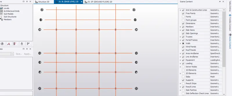
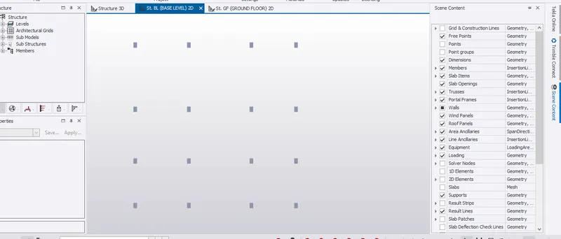
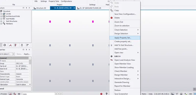
- Apply properties to pedestal member on grid line C and D (ie, at staircase and workshop). Therefore, pedestal sizes are changed to 400mmx 800mm
- 3 D view of the pedestal column is shown below.
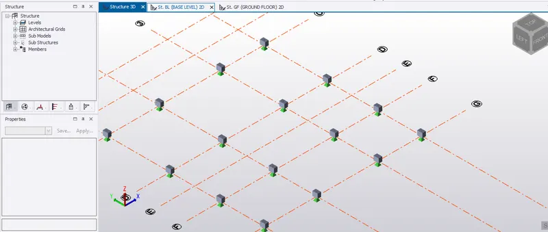
RESULT:- Therefore, column properties for different pedestal members are created and modelled them in grids created in assignment 1.
II. Create column properties for steel columns and model columns in the grid created as per assignment
AIM:- To create column properties for steel columns and model columns in the grid created as per assignment 1.
INTRODUCTION:- Tekla Structural Design is used for modelling, analysis and design of structural members. Over here, modelling of steel column members which starts from ground level surface. Steel structures are mainly used in industrial buildings. Steel column transfer all the structural load, ie, slab load is taken by the beams where the the portion of the slab load and beam load is taken by the column and thereby, column load to the foundation and then to soil inorder to keep the structure stable from failing.
PROCEDURE:-
- In ground floor level in the scene view, under HOME, go to MANAGE PROPERTY SETS.
- Click on NEW, from MEMBERS, select steel columns.
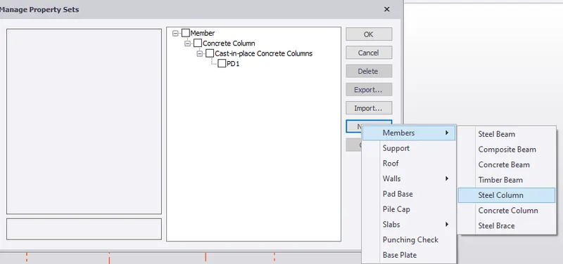
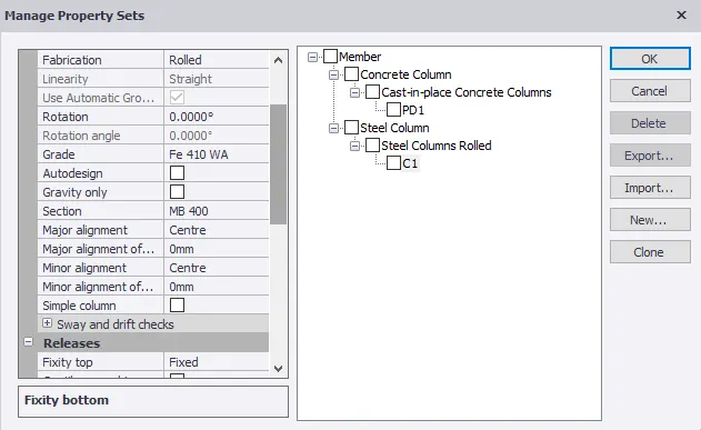
- Rename steel rooled column to C1.
- Select grade of steel as Fe 410 WA. Turn off Auto Design.
- Select steel section to ISMB 400.
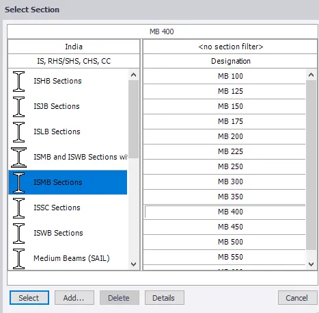
- Set major alignment to centre.
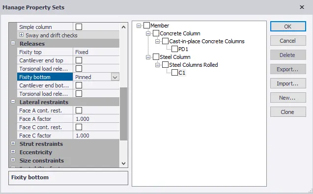
- Set releases with top fixity as fixed and bottom fixity as pinned.
- Click OK.
- Select ground floor 2D in scene view to model steel column from ground level to roof level.
- Click on Model in ribbon tool and select Column under the steel section.

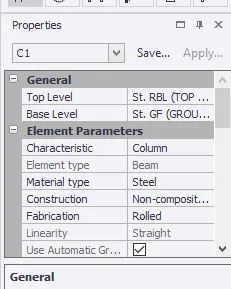
- Go to properties window, select column C1.
- Under general, select top level as top of roof beam level and bottom level as ground level.
- Also, once again check the properties for C1 column in property window.
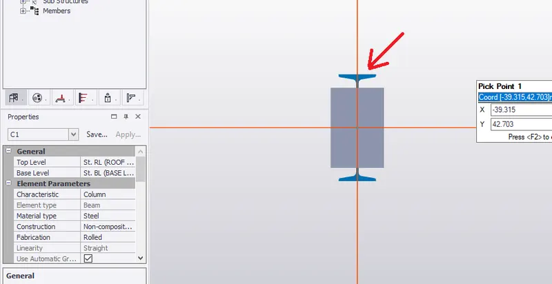
- Pick the intersecting point on the grid line C-1.
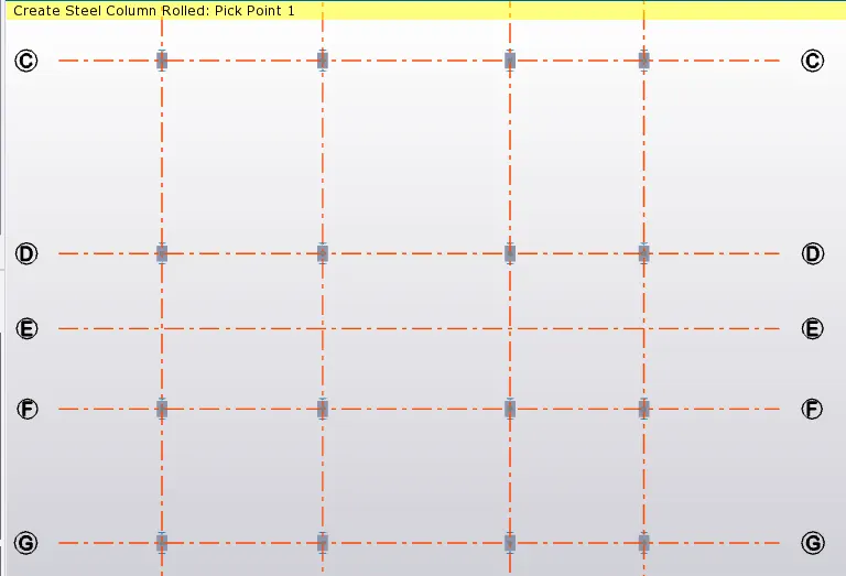
- Similarly, model steel columns on the grid line C, D, F and G.
- 3 D structural view is shown below
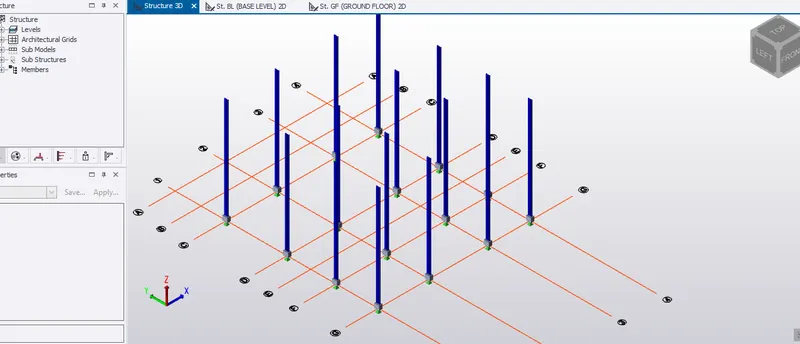
RESULT:- Therefore, column properties of the steel column is created and column modelling is done on the grid as per the assignment 1.
III. Create beam properties and model primary and secondary beams on the ground floor
AIM:- To create beam properties and model primary and beams on the ground floor.
INTRODUCTION:- Tekla Structural Design is used for modelling, analysis and design of structural members. Over here, modelling of steel beams in ground floor are carried out. Steel beams(primary beams and secondary beams) takes the slab loads which is then transfered to columns and then to foundation.
PROCEDURE:-
Primary Beam
- In ground floor level in the scene view, under HOME, go to MANAGE PROPERTY SETS.
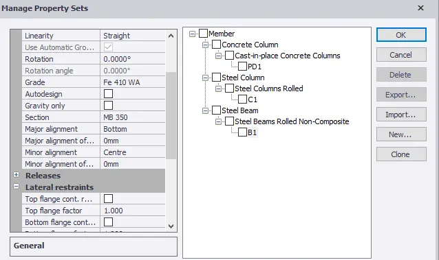
- Click on NEW, from MEMBERS, select steel beams.
- Name it as B1.
- Set steel grade to Fe 410 WA and steel section as MB 350.
- Set major alignment to bottom.
- Untick top flange cont.rest.
- Also, check the deflection limit.
- Click OK.
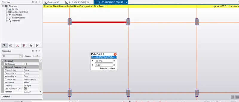
- Click on Model in ribbon tool and select Beam under the steel section.
- In property window, select B1 and check the properties for B1.
- Pick the first intersecting point of the grid line C-1 and pick the second point at grid line C-2 as shown below.
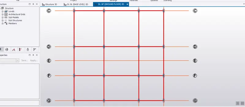
- Similarly, model primary beam on grid line from C-2 to C3 and from C-3 to C-4.
- There after, model primary beam on grid line D, F, G, 1,2,3 and 4.
Secondary Beam
- In ground floor level in the scene view, under HOME, go to MANAGE PROPERTY SETS.
- Click on NEW, from MEMBERS, select steel beams.
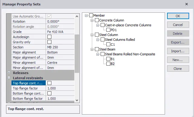
- Name it as B2.
- Set steel grade to Fe 410 WA and steel section as MB 250.
- Set major alignment to bottom.
- Untick top flange cont.rest.
- Also, check the deflection limit.
- Click OK.
- Click on Model in ribbon tool and select Beam under the steel section.
- In property window, select B2 and check the properties for B2.
- Pick the mid point of the beam B1(ie, 3m from grid line 1 as shown below.
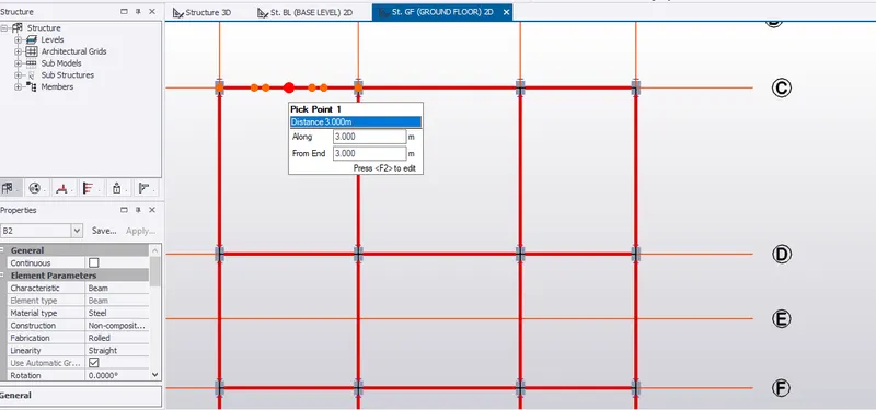
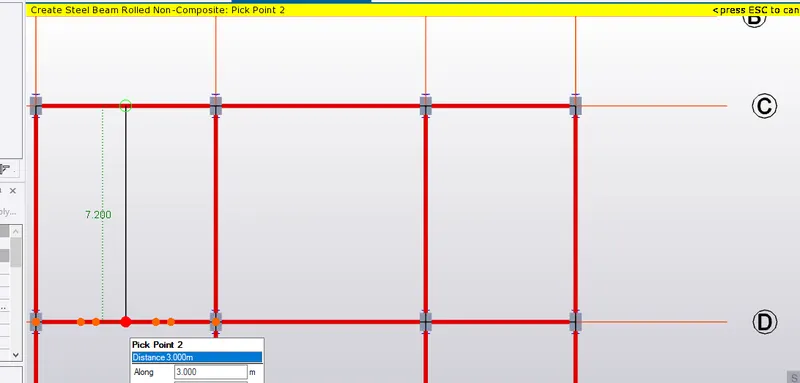
- Pick from the mid point and drag till it meets the mid point of another beam B1 as shown below.
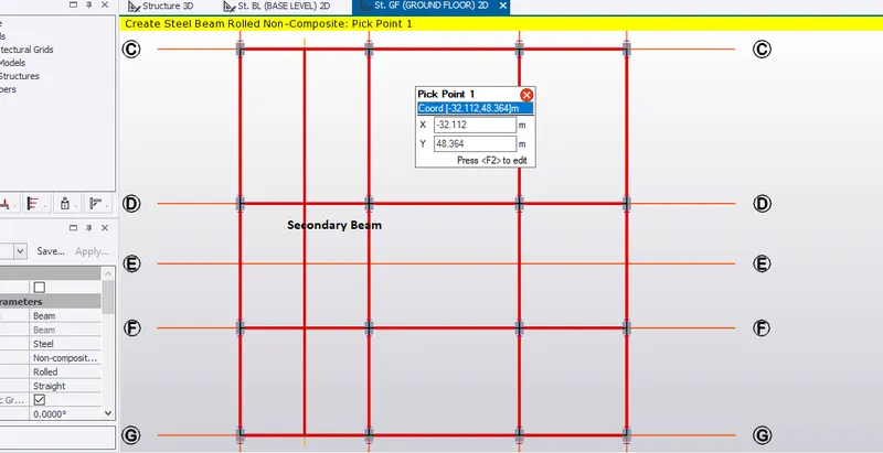
- Similarly, pick the mid point of primary beam on grid line D between 1 and 2 till it meets primary beam on grid line F and so on.
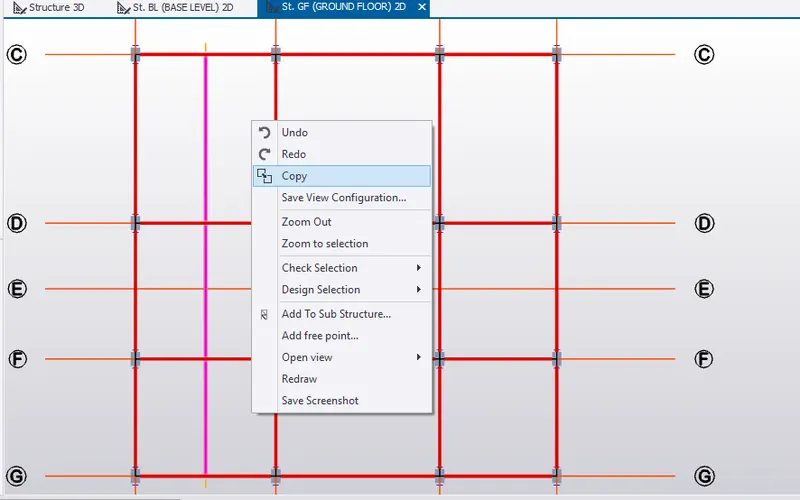
- Copy the 3 secondary beams between the grid line 1 and 2.
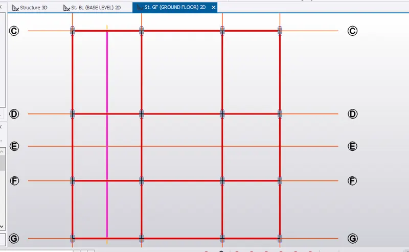
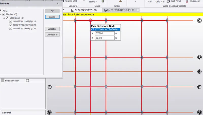
- Pick the reference point.
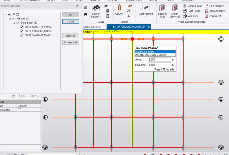
- Pick the new position mid point of the primary beam which is 3.5m from grid line 2.
- 3 D view of th secondary beam is shown below.
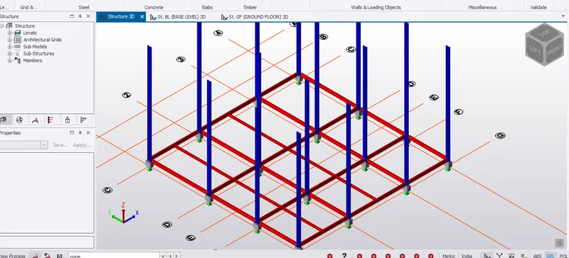
RESULT:- Beam properties are created and therefore, modelling of primary and seconadary beam on the ground floor are completed.