To model beams and bracings for industrial steel structures using TSD
To model beams and bracings for industrial steel structures using TSD
AIM:
- To create beam properties for First floor and to model the beams
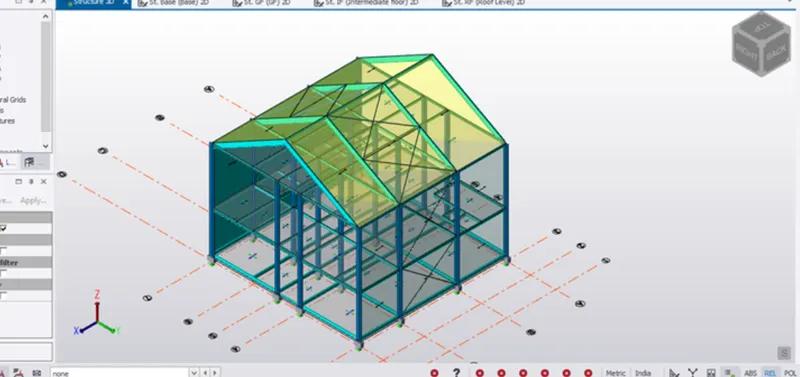
- To create rafter beam on second floor as roof and moment frame action in one direction and add bracings at locations as per the design intent
INTRODUCTION:
Rafter:
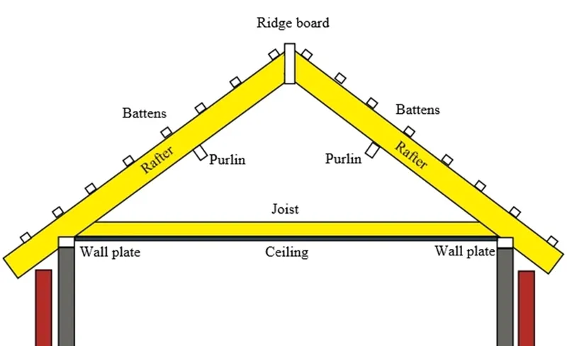
A rafter is a structural component that is used as part of a roof construction. Typically, it runs from the ridge or hip of the roof to the wall plate of the external wall. Rafters are generally laid in series, side by side, providing a base to support roof decks, roof coverings and so on.
Braced system:
A braced frame is a really strong structural system commonly used in structures subject to lateral loads such as wind and seismic pressure. The members in a braced frame are generally made of structural steel, which can work effectively both in tension and compression.
The beams and columns that form the frame carry vertical loads, and the bracing system carries the lateral loads. The positioning of braces, however, can be problematic as they can interfere with the design of the façade and the position of openings. Buildings adopting high-tech or post-modernist styles have responded to this by expressing bracing as an internal or external design feature.
The resistance to horizontal forces is provided by two bracing systems called:
Vertical bracing
Bracing between column lines (in vertical planes) provides load paths for the transference of horizontal forces to ground level. Framed buildings require at least three planes of vertical bracing to brace both directions in plan and to resist torsion about a vertical axis.
Horizontal bracing
The bracing at each floor (in horizontal planes) provides load paths for the transference of horizontal forces to the planes of vertical bracing. Horizontal bracing is needed at each floor level, however, the floor system itself may provide sufficient resistance. Roofs may require bracing.
PROCEDURE:
- Initially open the Tekla file which we are working on and it was modelled till the ground floor.
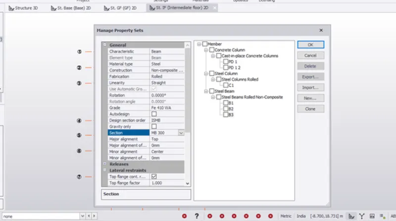
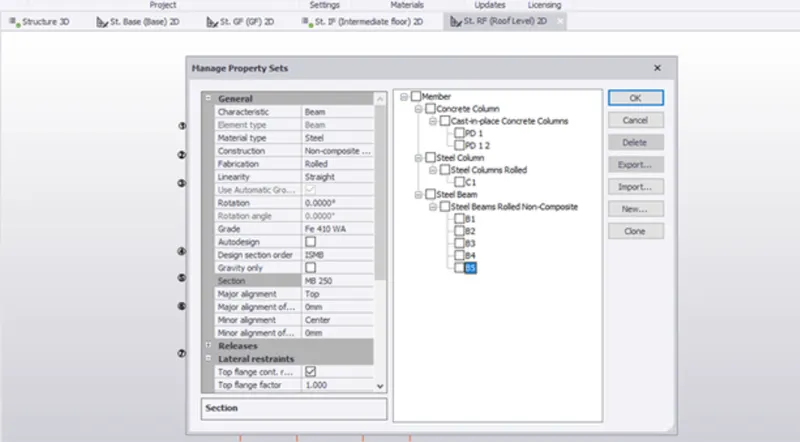
- In the Home menu click on Manage property sets options and the manage property sets dialogue box appears. Click on New followed by members and select Steel Beam. Rename the beam for our own convenience and apply the properties as required on the side.
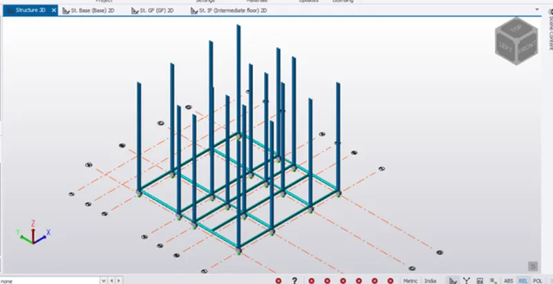
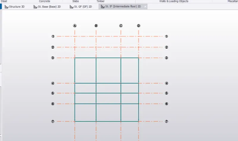
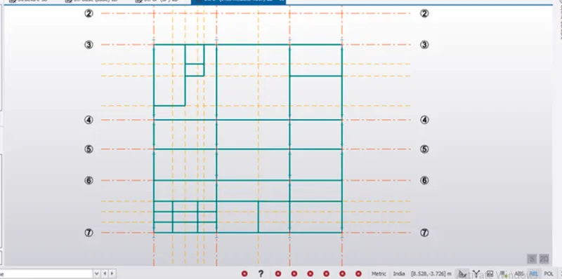
- Now in the intermediate/ first floor the primary beams were applied using the Beam option in the ribbon tab under the model menu and beams was placed at locations as required.
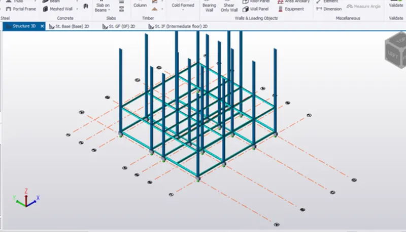
3D view of the same
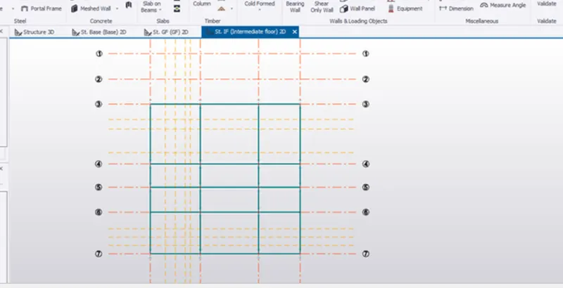
- Secondary beams are to be designed next for that we use the attachments provided in task. Now at places where beams are to be placed using the construction lines option the Model menu the required construction lines was drawn.
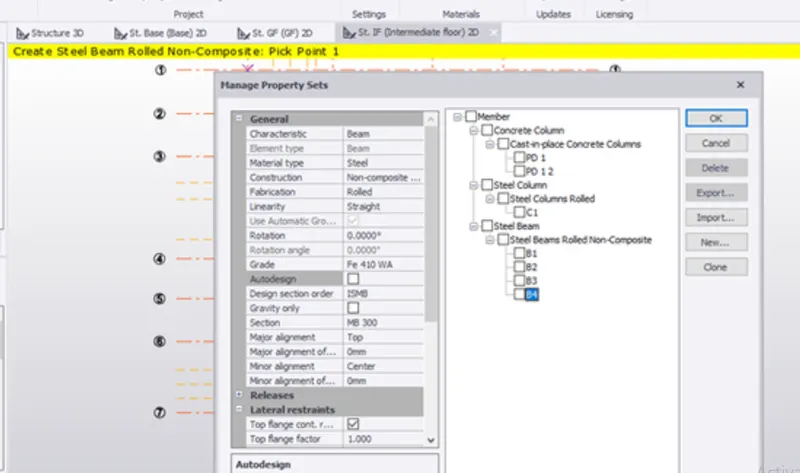
- For defining the secondary beams go to Home menu click on Manage property sets options and the manage property sets dialogue box appears. Click on New followed by members and select Steel Beam. Rename the beam for our own convenience and apply the properties as required on the side.
- Now in the intermediate/ first floor the secondary beams were applied using the Beam option in the ribbon tab under the model menu and beams was placed at locations as required.
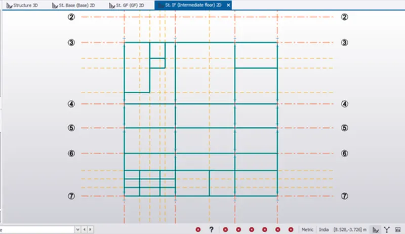
3D view of the same.
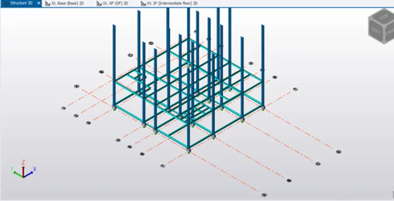
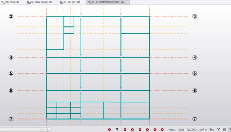
- After the modelling of primary and secondary beams in intermediate/first floor, the model was validated to check for any errors and no errors in model was found
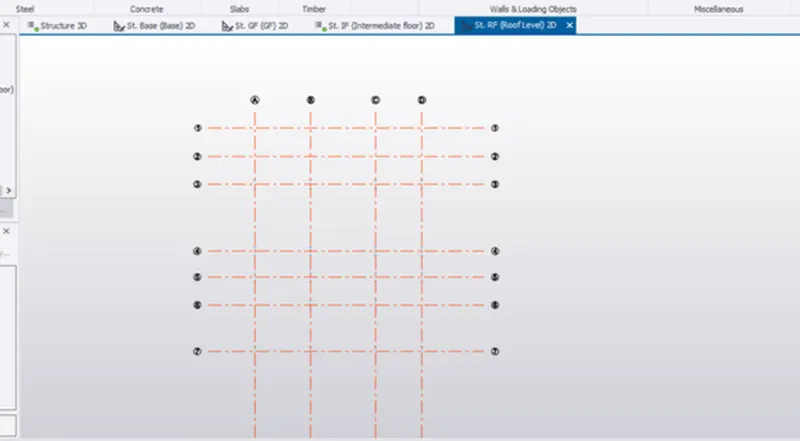
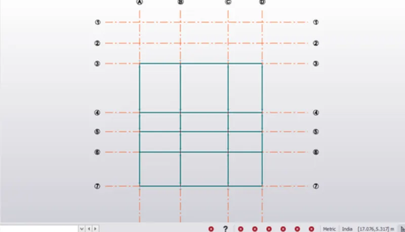
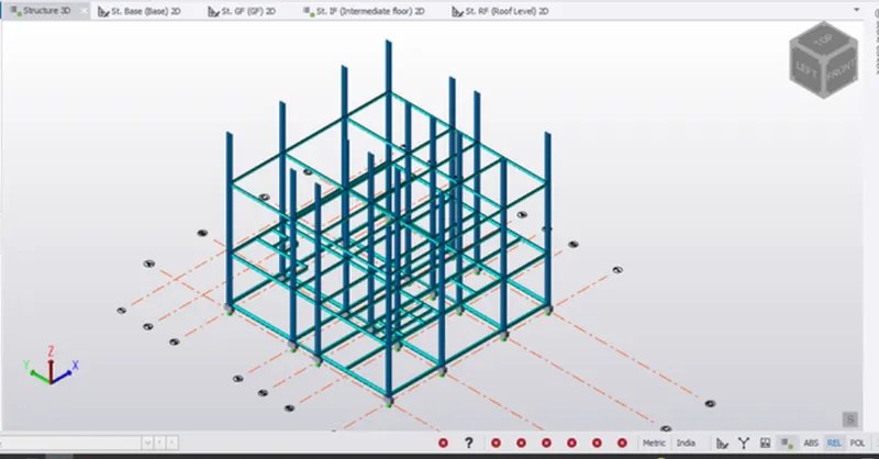
- The same way in which primary beams was designed in the intermediate/first floor the primary beams are designed in the roof level as shown below in images:
- Rafter beams was designed next for that click on Manage property sets options and the manage property sets dialogue box appears. Click on New followed by members and select Steel Beam. Rename the beam for our own convenience and apply the properties as required on the side.
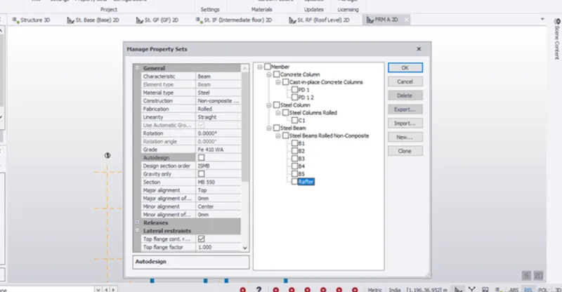
- A frame was created next, so that we can easily place the rafters, its created using the frame option in the model menu. Frame can only be created in the 3D view by selecting the required grid line a frame is created. The frame view of the gridline A is as shown below
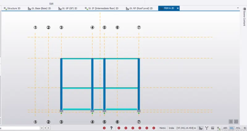
- Now the rafter beams were applied using the Beam option in the ribbon tab under the model menu and beams was placed at locations as required.
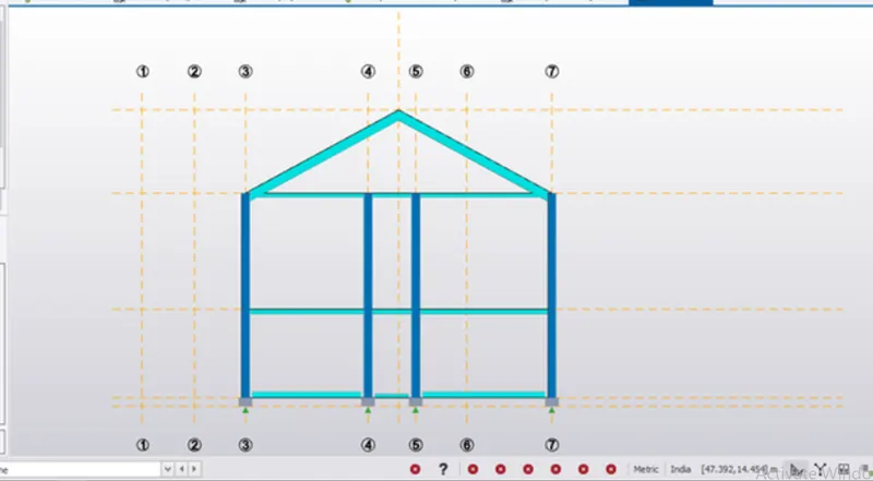
- The rafter beam releases was set to fully fixed at both the ends for both rafter beams.
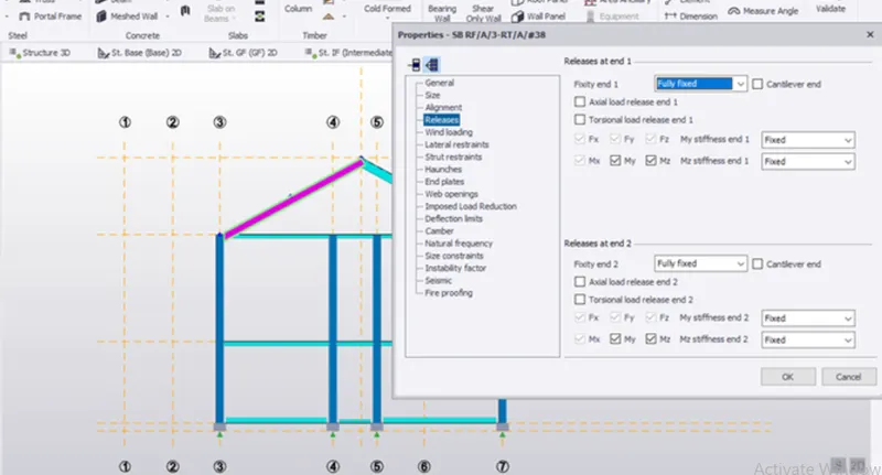
3D view of the same:
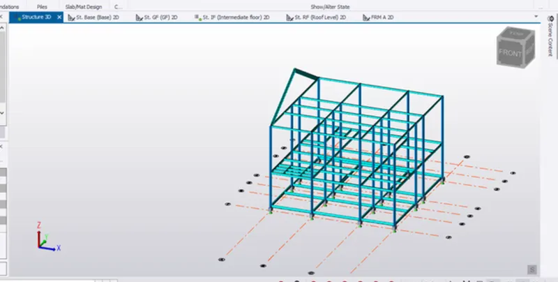
- Both the rafter beams was copied and was placed by picking a reference point and was placed at the columns as shown
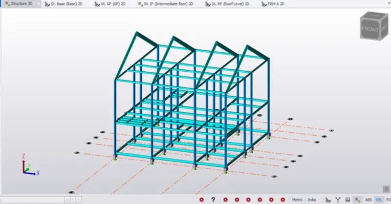
- Steel Bracings was designed next for that click on Manage property sets options and the manage property sets dialogue box appears. Click on New followed by members and select Steel Brace. Rename the beam for our own convenience and apply the properties as required on the side.
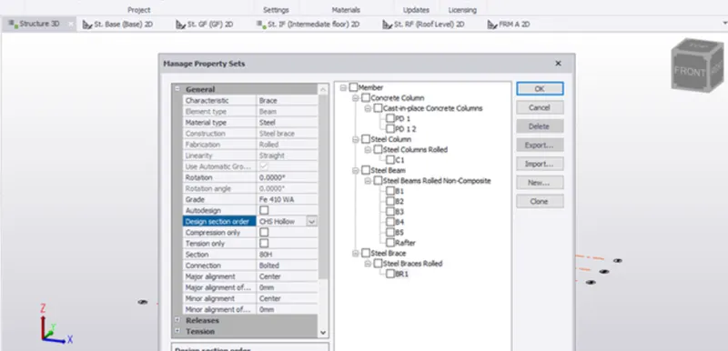
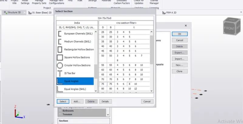
- Section of size ISA 75X75X8 was chosen for designing the brace.
- Now the steel braces were applied using the Brace option in the ribbon tab under the model menu and braces was placed at locations by selecting 2 opposite corner points. X Brace option was selected and drawn. For convenience the braces as drawn on frames on both sides.
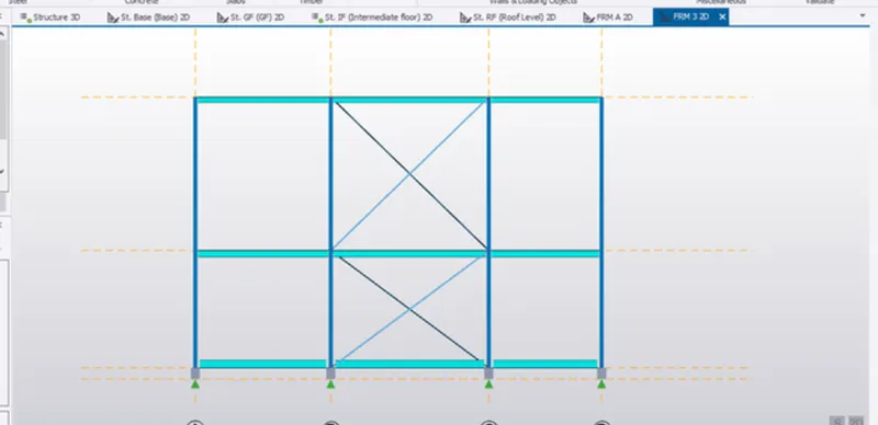
3D view of the same.
- The model was validated to check for any errors in the model.
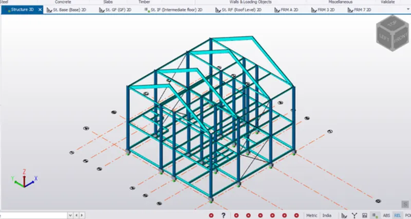
- Now the braces were designed on the roof in 3d view in the same as done before.
3D view of the same is as follows.
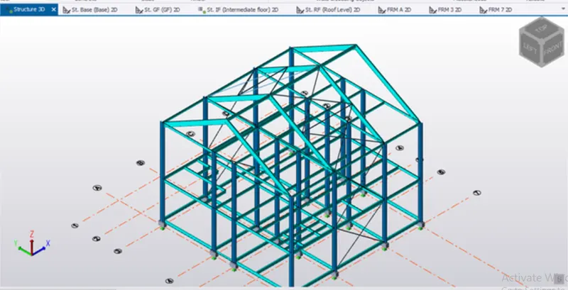
- For distributing loads the wall panels was applied to the column using the wall panel option from the model menu.
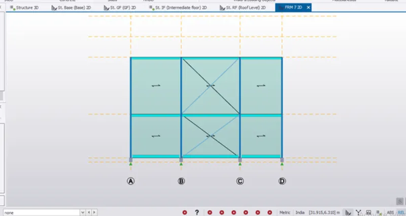
3D view of the same:
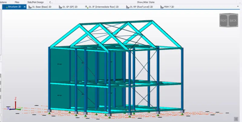
- In the same manner the wall panel was applied to the opposite columns as shown.
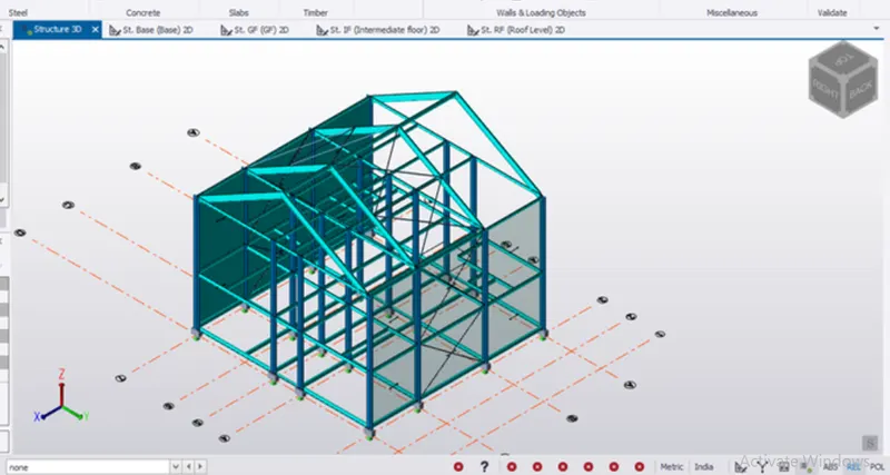
- In the same way wall panels was made next the roof panels were created and it is also used for distribution of the load and 3D view of the same is a shown.
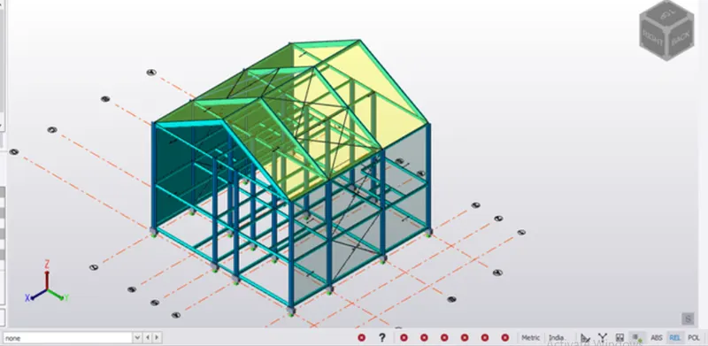
- Slab properties was designed next for that click on Manage property sets options and the manage property sets dialogue box appears. Click on New followed by members and select Slabs followed by general slab item. Rename the slab for our own convenience and apply the properties as required on the side.
Slab properties:
Grade M25
Overall Depth 200mm
Rotation 90 degree
One way and Two-way slab were modelled with the same properties. And can be distinguished by taking the x/y ratios
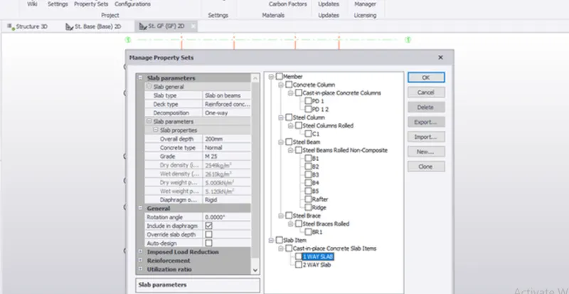
Now using the slab on beam option in model menu the slabs was applied on all floors the ground floor, intermediate floor and roof level too.
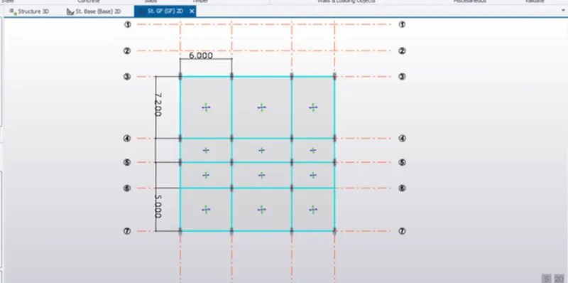
3D view of the same.
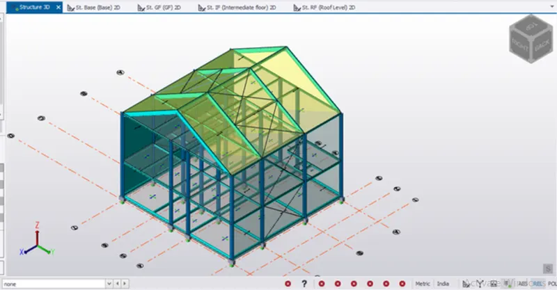
RESULTS:
- Started with designing and modelling of primary and secondary beams in the first/intermediate floor and is a shown below.
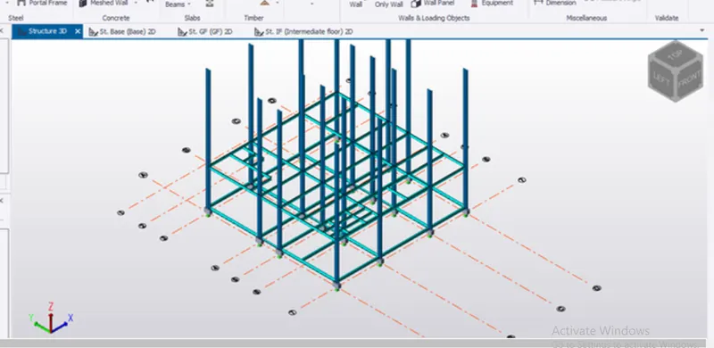
- Rafter Beam was designed and was modelled in the roof
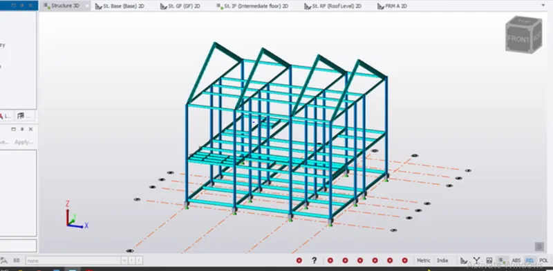
3.Steel bracing was done as required
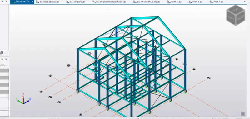
- Wall panel and roof panel was designed and modelled in both wall and roof
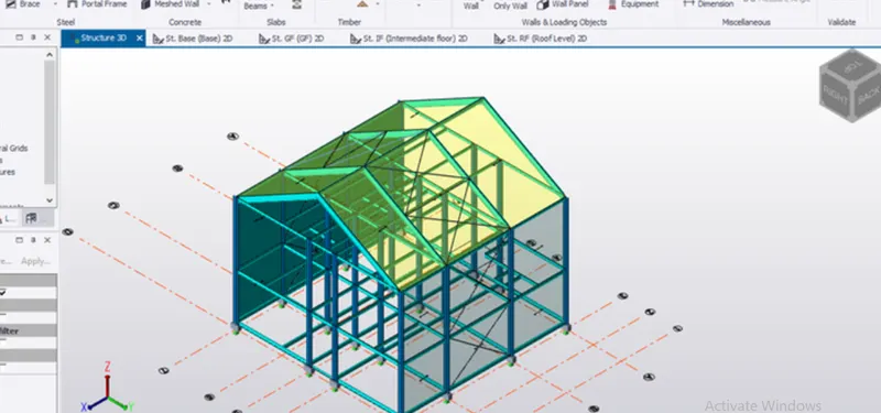
- Slab property was defined on all floors