To model beams and bracings for industrial steel structures using TSD
1. Create beam properties for First floor and model the beams.
AIM: Create beam properties for First Floor and model the beams.
Introduction: Using Tekla Structural Designer (TSD) we need to create the beam properties for First Floor similarly like the last challenge using the data from the attachments provided.
Procedure:
- Open the previous file on which we were working on week 2 named Question-2.
- Follow the same procedure to create properties for 1st floor
- Click on Home -Manage Property set
- Click on New - Member - Steel beam
- Rename it as B4 (ISMB-300) with Major allignment bottom.
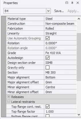
- Previous applied properties of beams B1 (ISMB-350), B2 (ISMB-400), B3 (ISMB-250) with Major alignment Bottom.
- Columns C1 and C2 (ISMB-350) with Major Allignment Centre.
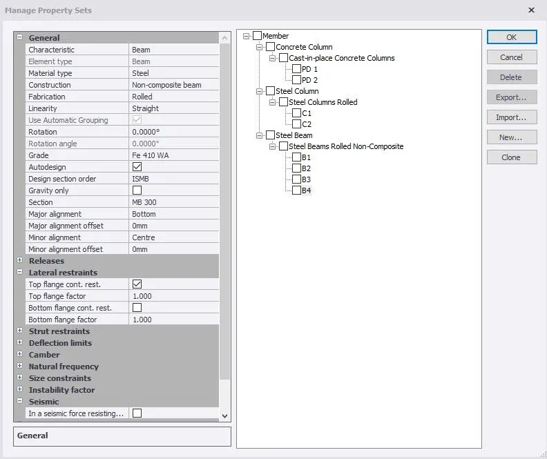
-
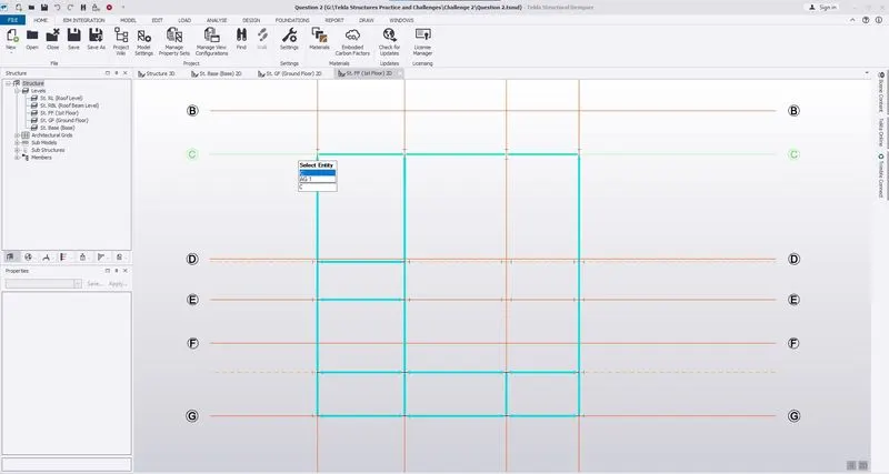
As the property is defined, Open the First floor attachments and add the Primary beams as shown below
-
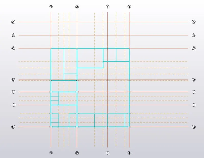
Open the 1st floor plan and add the secondary beams. Dimensions are given in floor plan. Draw the Construction lines to make it easier to draw secondary beams. take secondary beams as B5 (ISMB 150).
- 3D view is as follows
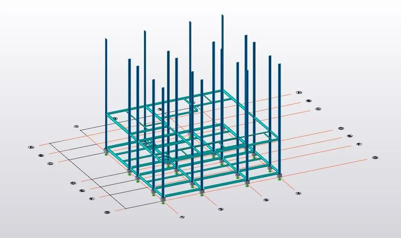
-
Check the model or Validate the model to see if an error is present or not
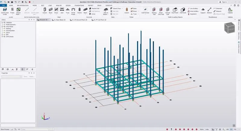
No error. Hence, modelling is OK.
-
As the beams are modelled for Ground floor , 1st Floor. We have to create a beams for Roof level also. So similary create the primary beams for Roof level. Go to Home - Manage Property Set - Member - Steel Beams. Rename it as B6 and Assign as section ISMB 500.
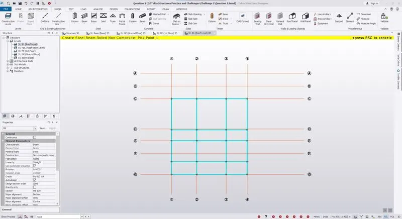
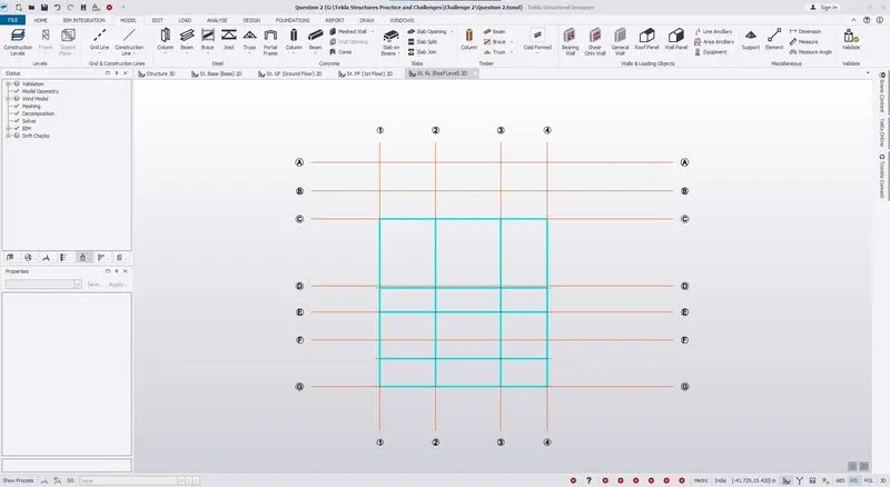
- Check the model or Validate the model to see if an error is present or not
No error. Hence, modelling is OK.
2. Create rafter beam on second floor as roof and moment frame action in one direction and add bracings at locations as per the design intent
AIM: To create a rafter beam on second floor as roof and moment frame action in one direction and add bracings at locations as per the design intent.
Procedure:
-
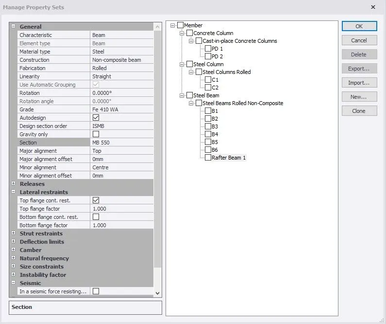
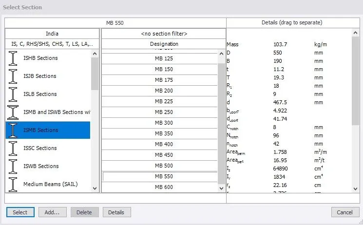
For Rafter first we have to create the Rafter properties. Go to Home - Manage property set - Member - Steel beam, Name it as - Rafter Beam 1. Select section as - ISMB 550
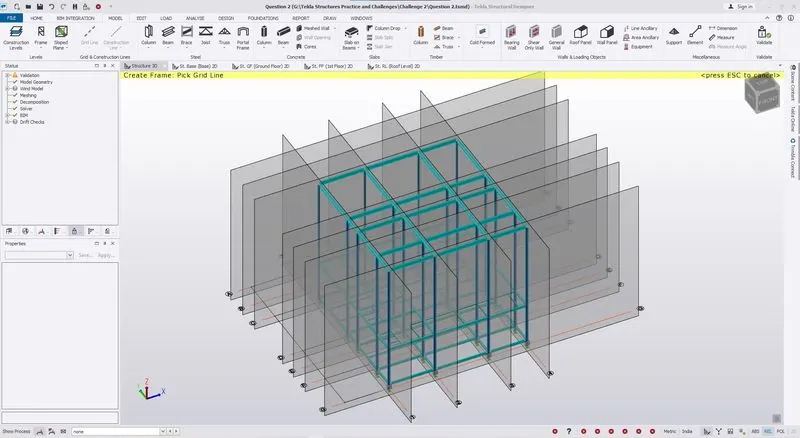
- Create a Frame so that it will be easier to see the cross sections. Go to Model - Frame. Create the frames on grid lines as shown below:
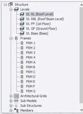
- Frames created are categorised and shown this way:
- Click on Frame 1 to draw the rafter of ISMB 550.
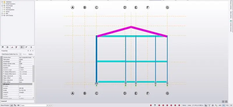
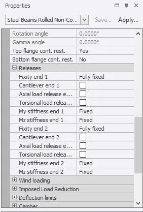
- Draw the Rafter by picking up the points. If the points are not snappable then create construction lines as per the given dimension. Now, Change the property of Rafter from pin to Fully Fixed at Fixity end 1 and Fixity end 2.
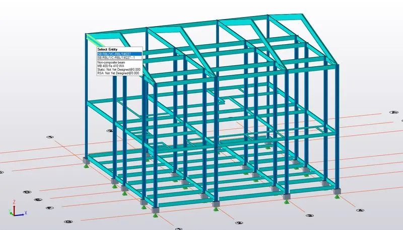
- Similarly create rafters of ISMB 550 for Frames 2, 3 and 4. Hence, The 3D model is as follows. Then, connect all the beams at Roof beam level joining the Rafter.
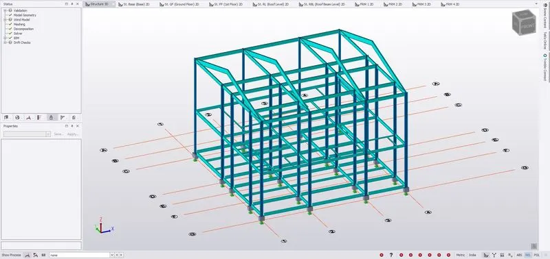
- Validate the model and check for any errors.
-
Follow the same procedure to create bracing properties. Home - Manage property set - Member - Steel brace. Rename it as - BR1. Select section as - ISA 90 x 90 x 10.
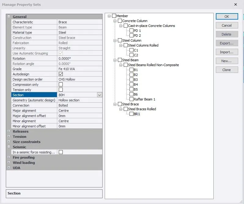
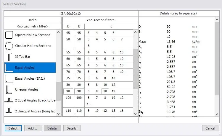
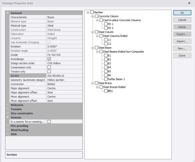
- Now go to Model - Steel Brace - select X bracing with BR1 and apply
-
Similarly we have to apply bracings on Roof also. Select the X bracing and draw the bracings on Roof also.
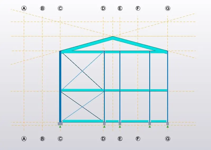
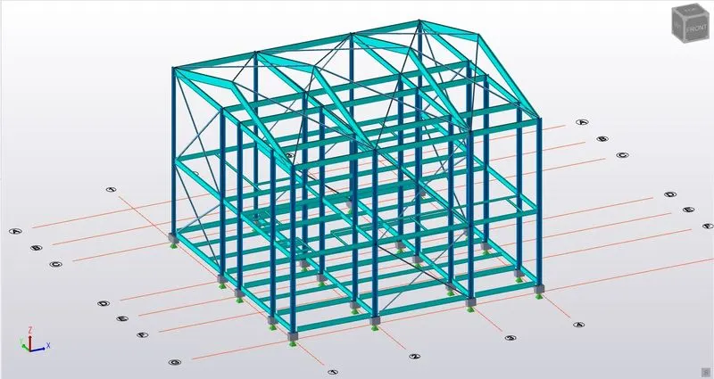
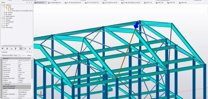
- Validate the model and check for any errors. If error comes, simply switch off autodesign and again check. Now it should be ok.
- Creation of wall Panel and Roof panel:
Wall panels are created to distribute the lateral load uniformly
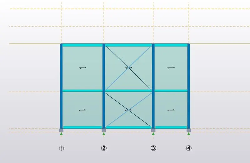
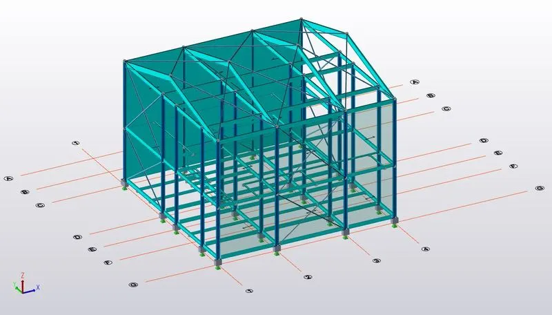
Go to Model - Wall panel. Select the Frame C and Frame G and draw the wall panel.
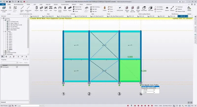
Frame- C
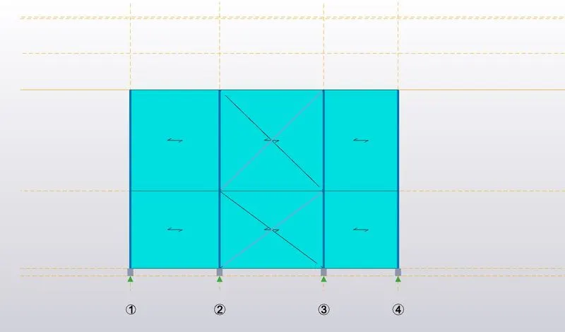
Frame- G
3D View
-
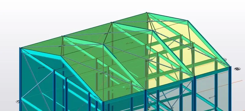
Similarly draw the roof panel also. Pick up the reference point 1, 2, 3, 4 & 5 and draw roof panel also.
- Slab Properties -
Slab properties is next to be designed
For that click on Manage property sets options and the manage property sets dialogue box appears.
Click on New followed by members and select Slabs followed by general slab item.
Name it as S1 and S2
S1 = One way slab
S2 = Two way slab
Slab properties:
- Grade M25
- Overall Depth 200mm
- Rotation 0 degree.
- One way and Two-way slab were modelled with the same properties.
And can be distinguished by taking the Lx/Ly ratios
Ground Floor
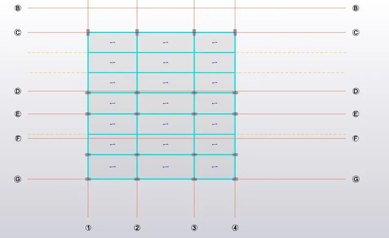
First Floor
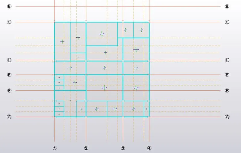
3D View
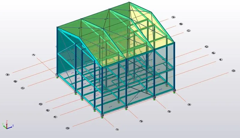
Result:
Both questions 1 and 2 are answered with proper explanations and pictures. Main file is attached with this challenge.