To Generate seismic loading based on IS code and to run the analysis using TSD
1.Generate seismic loading based IS codal provisions and zone II. Any other data you can assume and input accordingly
AIM:- To generate seismic loading based IS codal provisions and zone II. Any other data you can assume and input accordingly
INTRODUCTION:-Sesimic load are the earthquake load on the structure which acts from ground and transfer to the top the building. The structure must be designed in such a manner to resist the seismic forces. IS 1893 part 1 are followed for seismic loadcase.
PROCEDURE:-
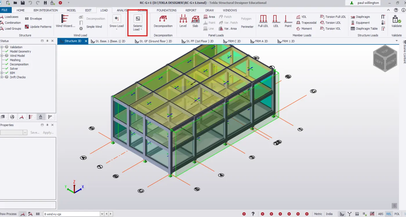
- Select seismic load (seismic wizard) ribbbon from Load tab.
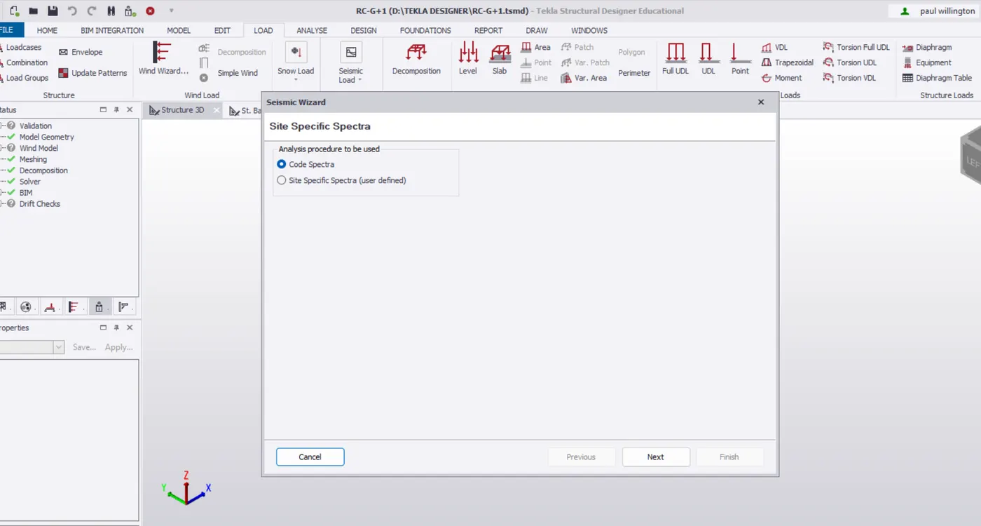
- Select code spectra for analysis procedure. Click Next.
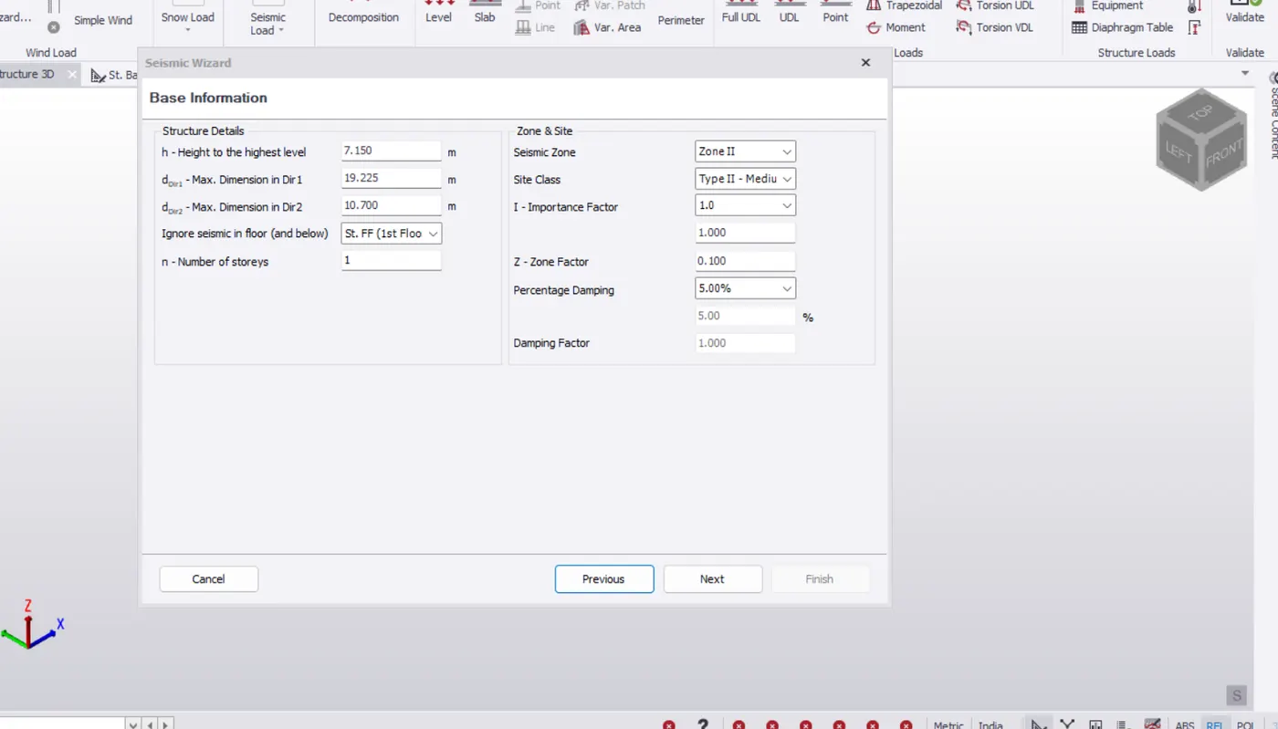
- Structure Details under base information is automatically inputed.
- Set the seismic xone to 2 and site class to 2 as shewn below.
- Imprtance factor and percentage damping is obtained from Table 6 and 3 respectively of IS 1893-1 and xone factor from Table-2
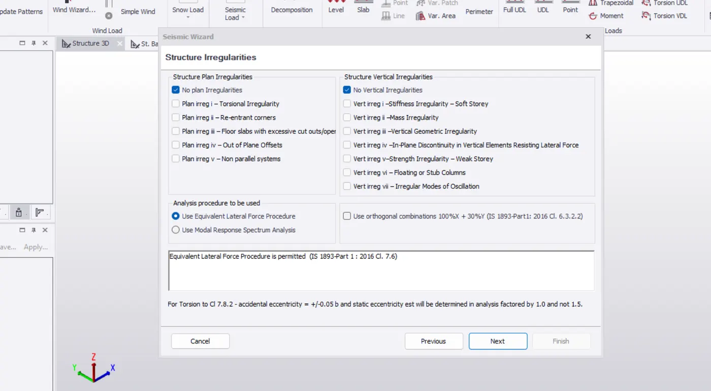
- No structural irregularity in the structure as mentioned in Table 4 and 5.
- Use approxmiate fundamental period. Set RC MRF building without any masonry infill in both direction.
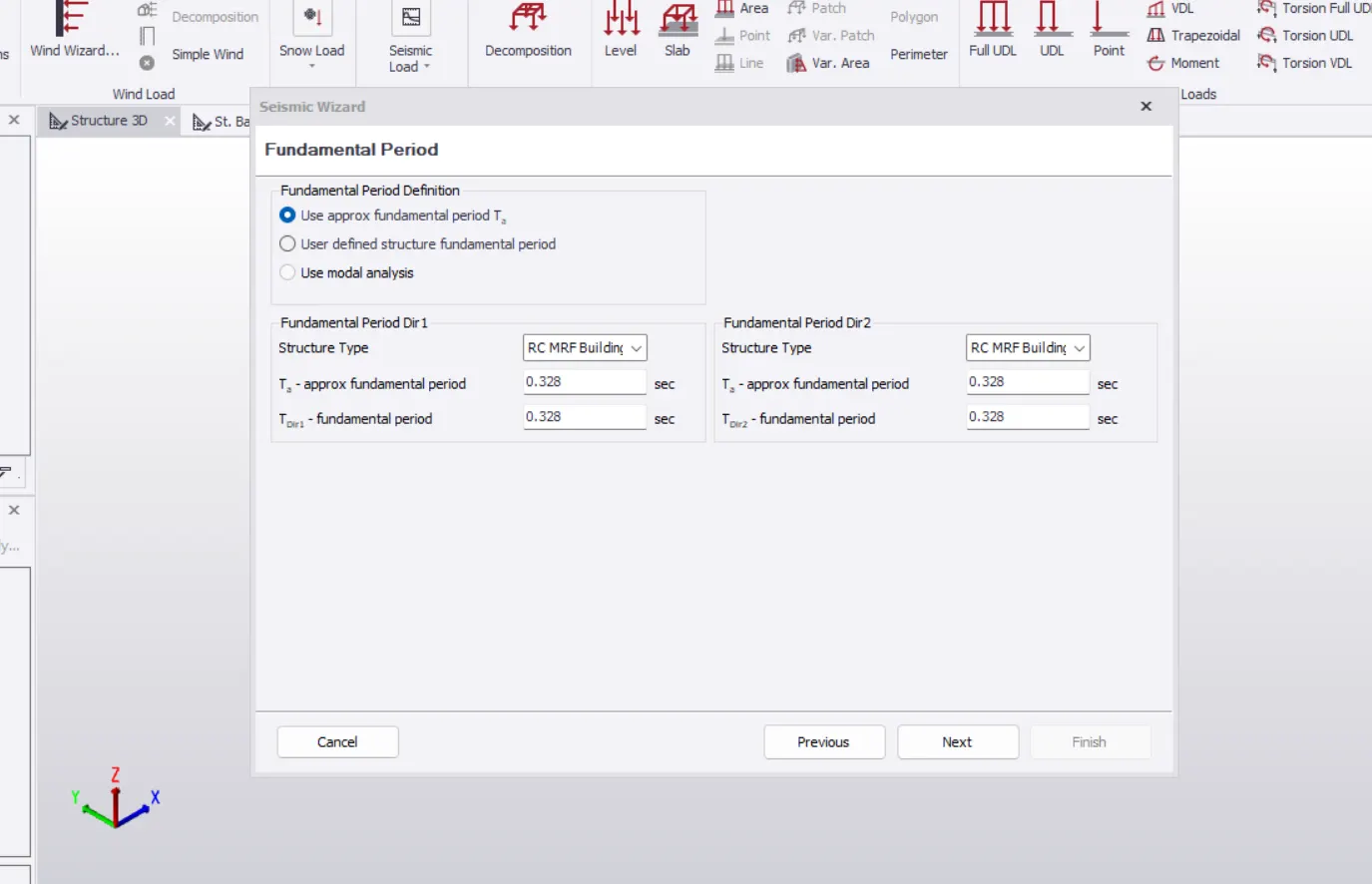
- Set structure type to seismic force resisting system in both direction.
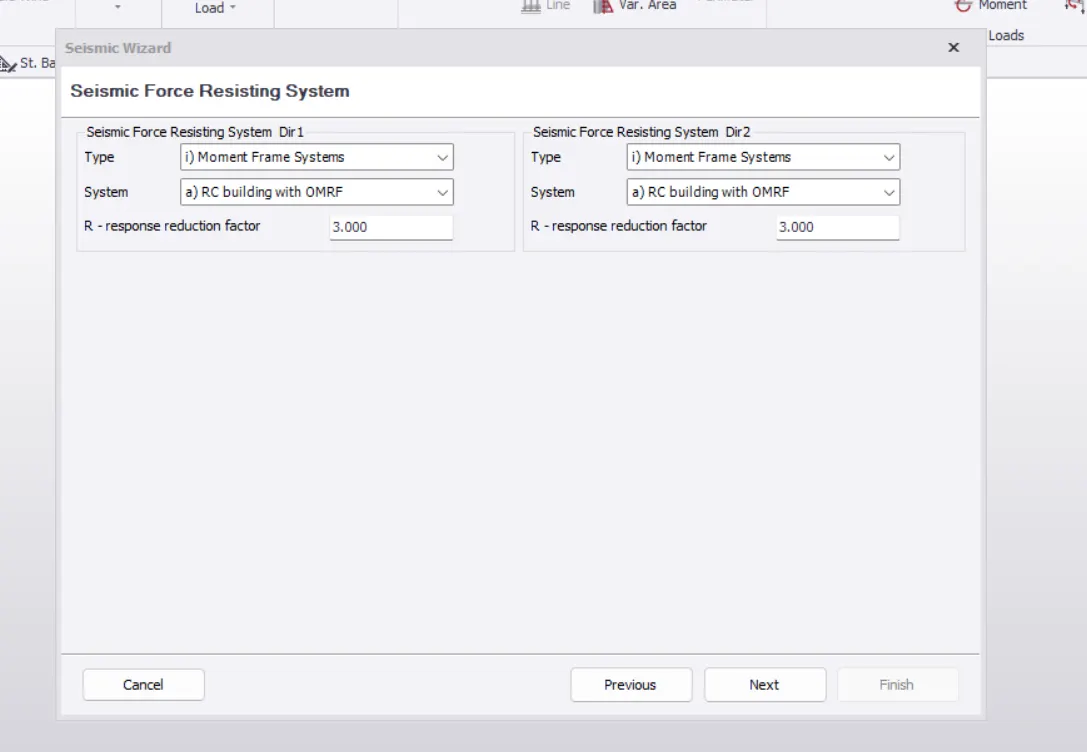
- Select all the locases and set factor for imposed load 25% for refered from table 8
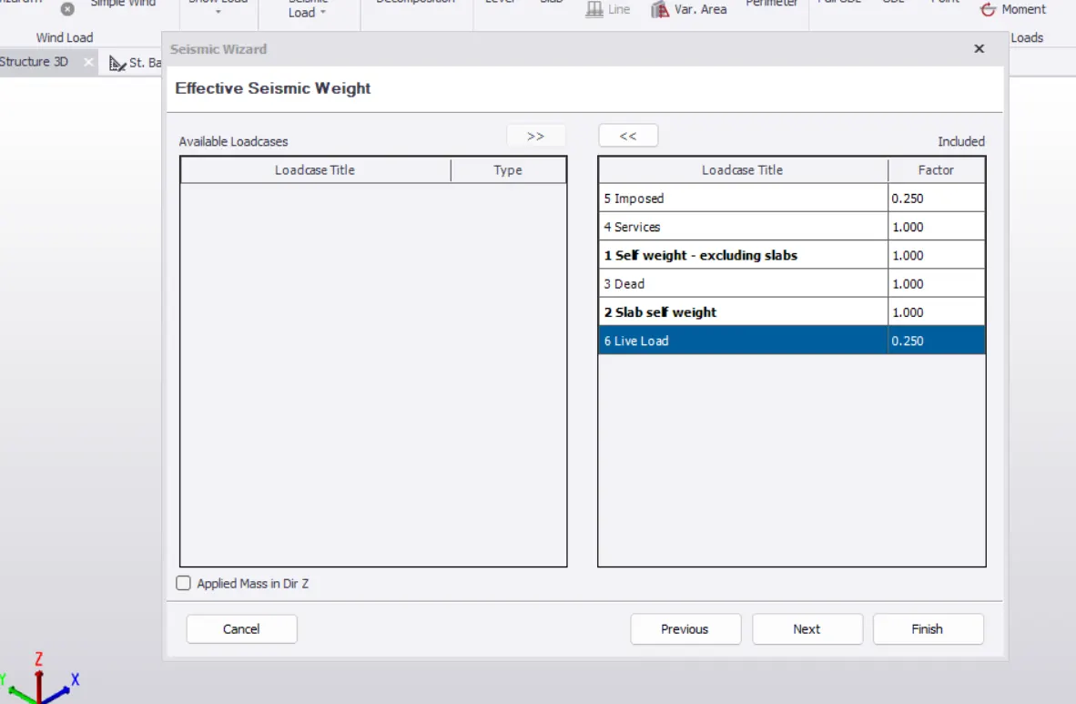
- Set allowable storey dirft factor as 0.004. Click finish.
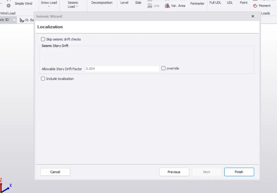
- Delete all previously combinations.
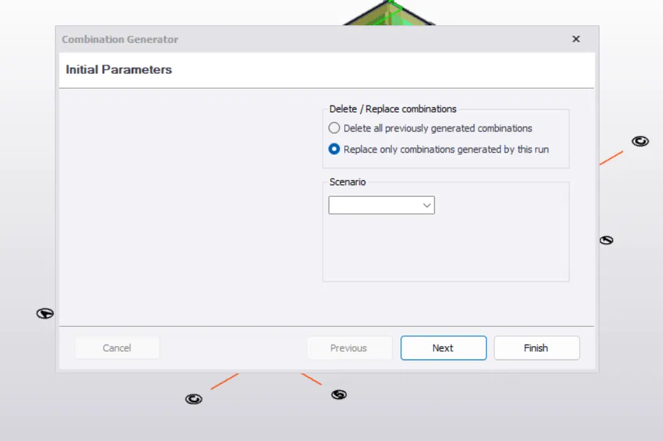
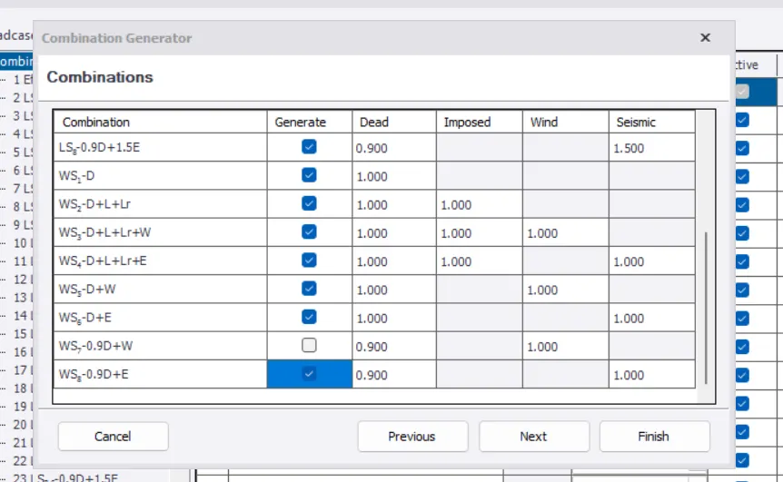
- Select the combinations to be generated.
- Select the load combinations from load tab to check the combinatio generated.
- Click on generate to replace only combinations generated by this run.
- Click finish
- Therefore, load combinations are generated.
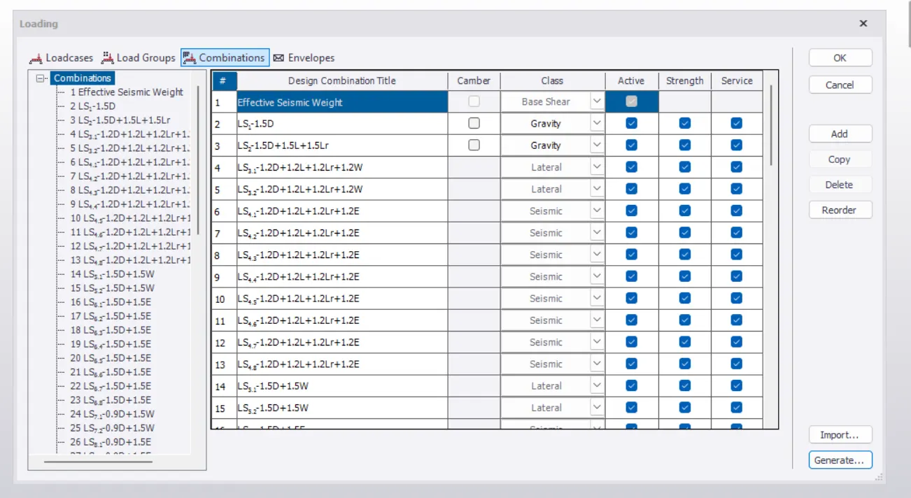
RESULT:- Hence the analysis loading are generated based IS codal provisions Zone II
2.Run the analysis. Summarize your understanding of the analysis results
AIM:- To run the analyical diagrams like Bending moment, shear force , Axial force and deflection are used for the study of behaviour of each member of the building.
PROCEDURE:-
- Go to analyse, under settings check modification factor for concrete as 1.
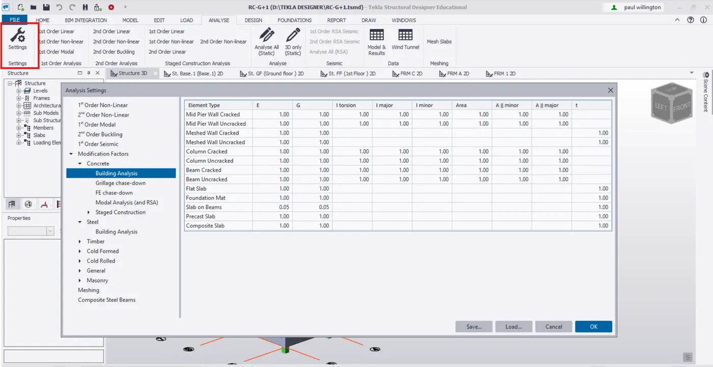
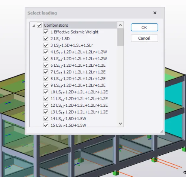
- Run under 1st order analysis . Select all load combinations.
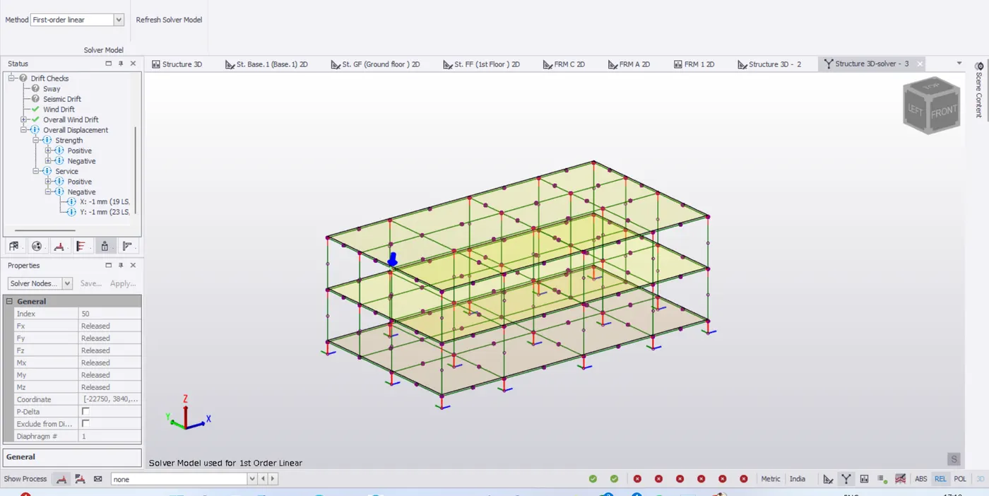
- After run analysis, the status shows no error.
- Expand the overall displacement, check the maximum postive displacement for both strength and service in solver view.
- Highlight the node for displacement for the member as shown
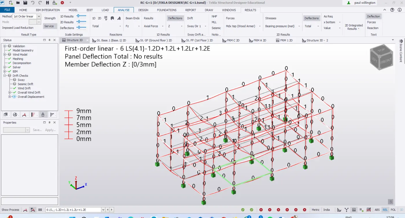
- In results view, under results select deflections for different load combinations. Therefore, maximum deflections is shown load combination 3
- Select the frame 3 from project window , to check the deflection diagram.
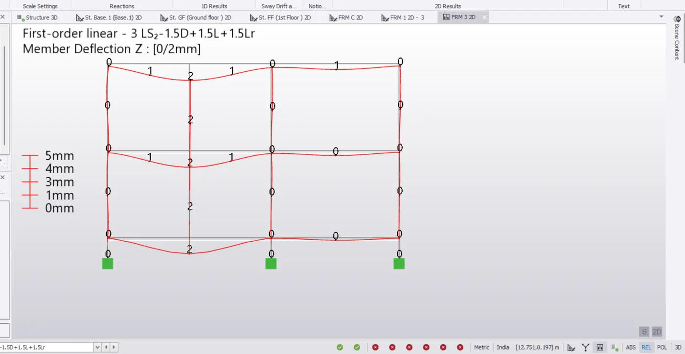
- The deflection due to gravity in piture above is correct.
- But the deflection at the cantilever ends high.
- SImilarly, check for differefnt load combinations.
- Deflection due to wind is shown below.
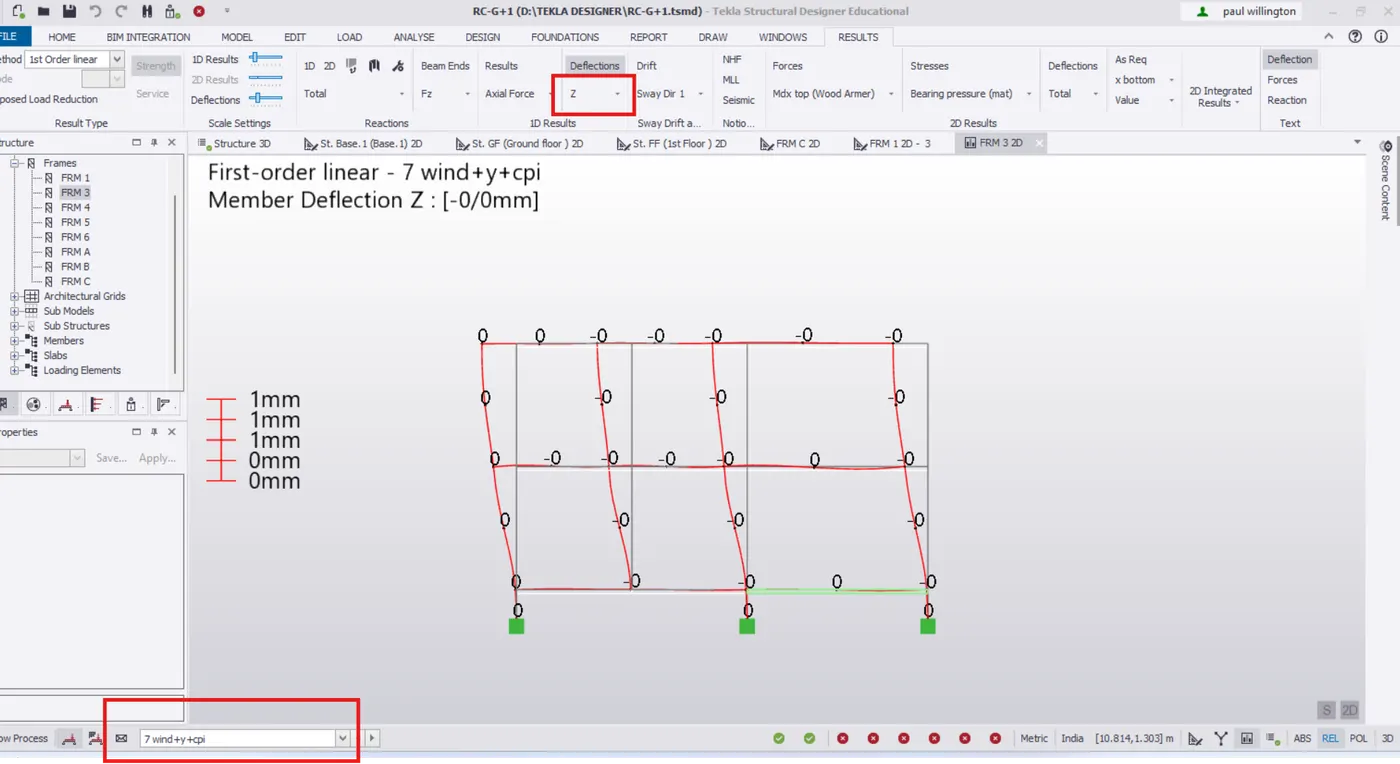
- In result view, select Axial force from result tab.
- Maximum axial force for column is shown for load combination 3.
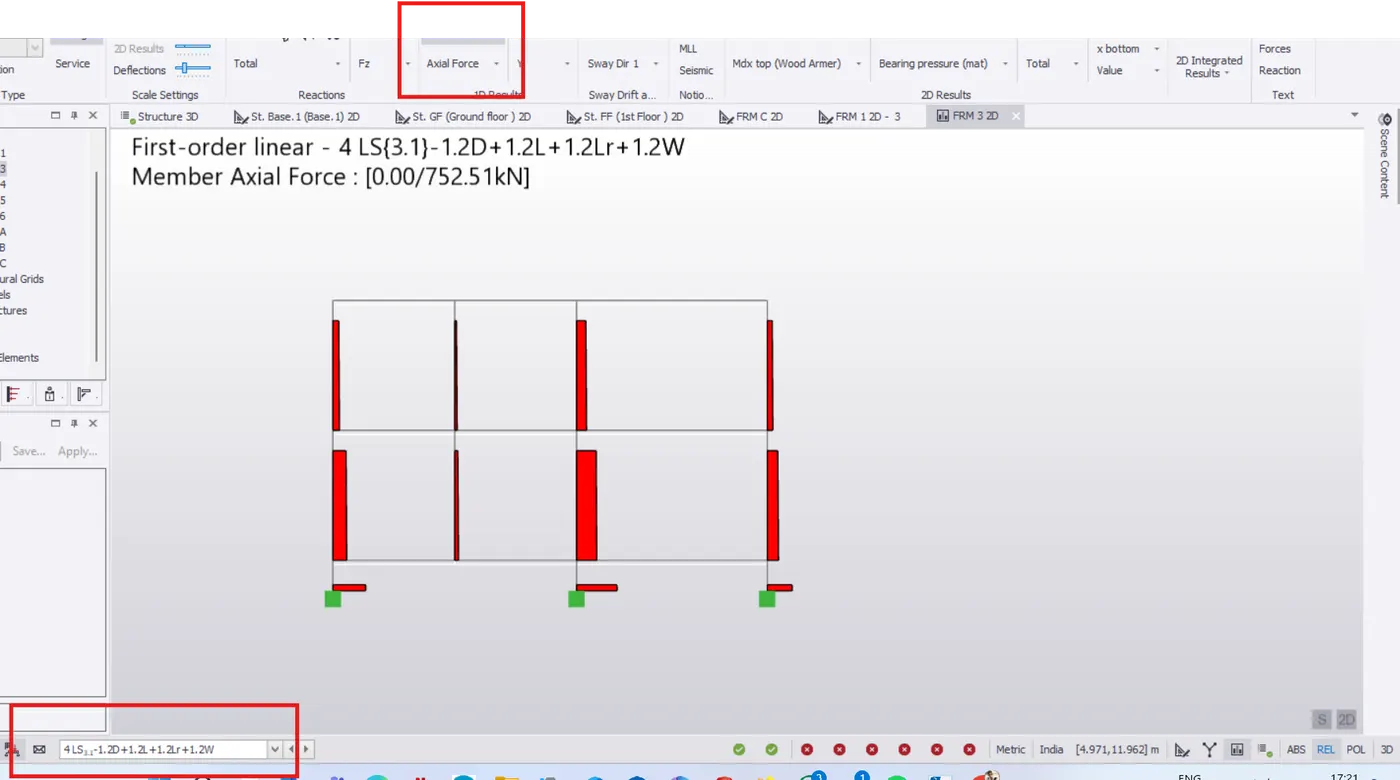
- Select the frame 3 from project window, to check the axial force diagra.
- The axial force is acting maximum at bottom of the column which is correct.
- Similarly, check for different load combinations
- For frame 3, select moment major from result tab.
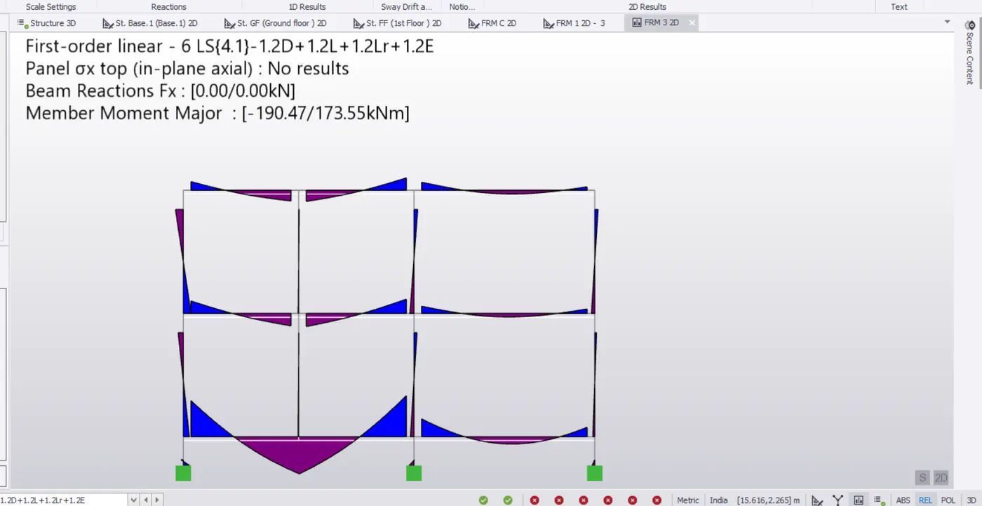
- Bending moment at the end of the cantiliever beam is 0 which is corrct.
- Similarly, check for different load combinations such as wind and seismic.
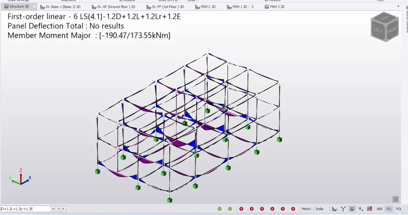
Shear force:
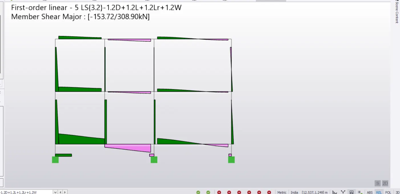
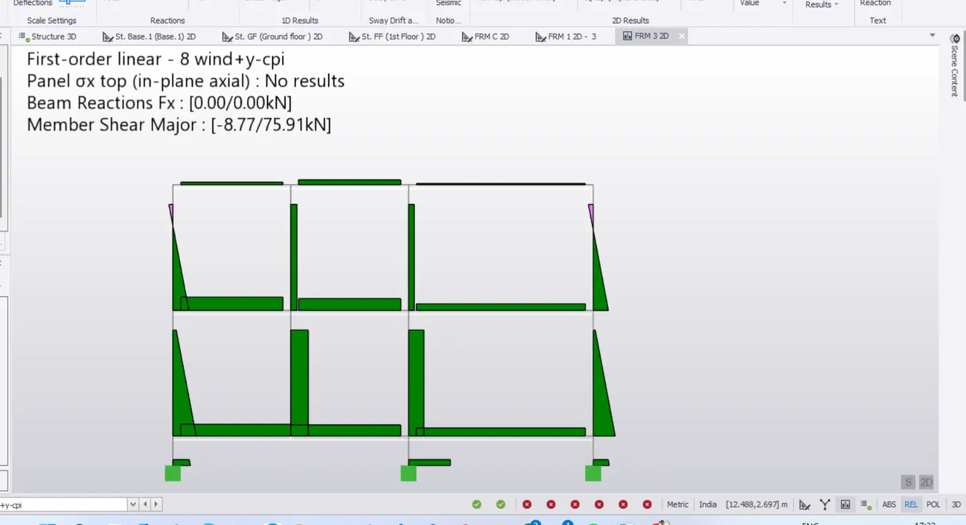
- For fame 3, select shear major from result tab.
- Check shear major for difference load combinations and combinations.
RESULT:- Hence, summarized the analysis results obtained after run analysis.