To Generate report for Steel Industrial and RC structures using TSD
Generate report for the steel building design from challenges 1 – 6 along with the loading summary
Aim: To generate report for the steel building design.
Procedure:
Open the saved Tekla model
Now go to the report option from the Ribbon and select model report.
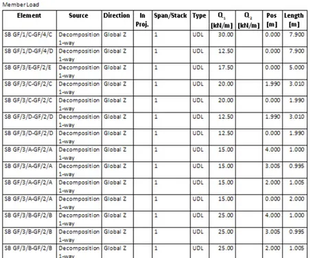
Now select the load cases and combinations summary to obtain report.
Click on the Show report to obtain the report
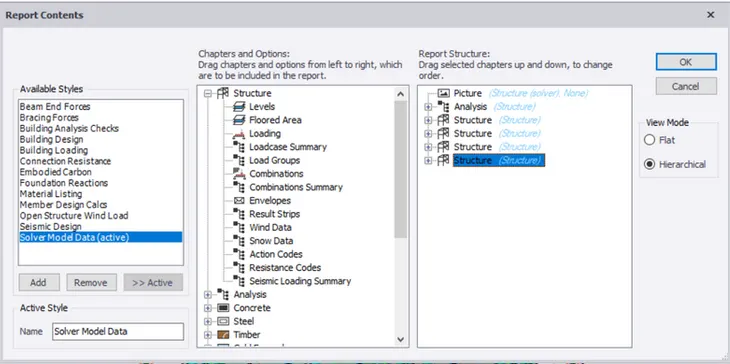
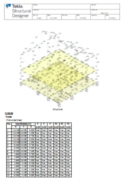
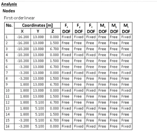
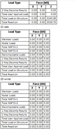
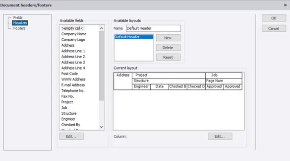
We can change the project name, address etc, with the help of edit header option
We can also convert this report in PDF, word etc as well.
2.
Aim: To generate the report for RC structure along with loading summary.
Procedure:
Open the previously saved Tekla model
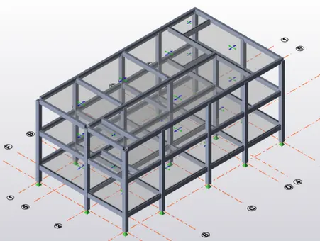
Now go to the report option from the ribbon and select model report.
Now select load cases and combinations summary to obtain report.
Now click on show report option to obtain the report.
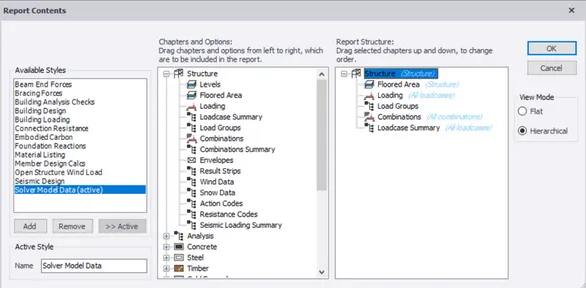
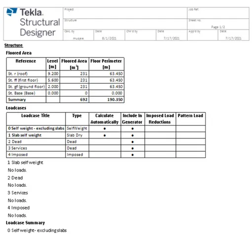
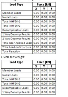
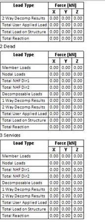
We can make changes in the settings, project name, type etc; using the Edit header
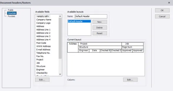
We can convert this report to PCF , word format etc.
3.
Aim: To update the layers settings in the model and generate plan drawings and details from the model.
Procedure:
Go to the setting option from the ribbon.
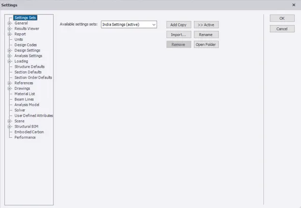
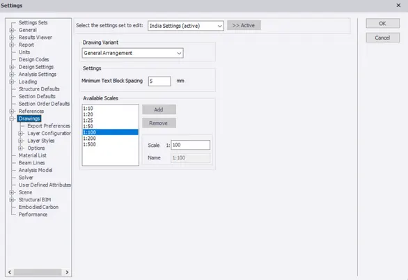
Now select the drawing option and adjust the scale and sub layer configuration.
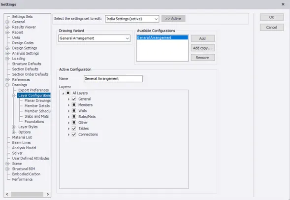
Now we have to select the layer style and we will get the list of colours od different members of the model, which is our choice.
Click on a colour and then select the desired colour for our desired member.
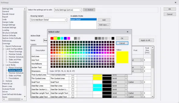
Thus, we can make changes in the layer settings
1)
Aim:
To Generate report for the steel building design from challenges 1 – 6 along with the loading summary using Tekla Software
Procedure :-
Step 1:
1) Go to report tab
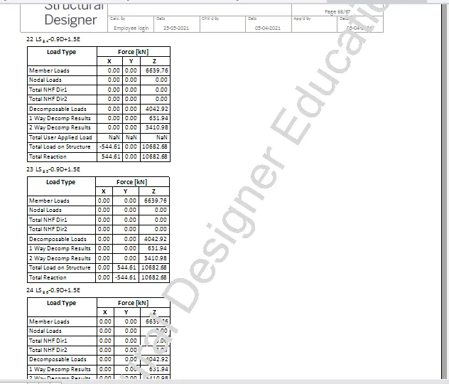
2) Select the levels, load, loadcase and combination
3) Click ok
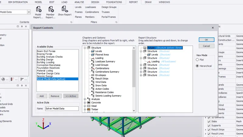
Step 2:
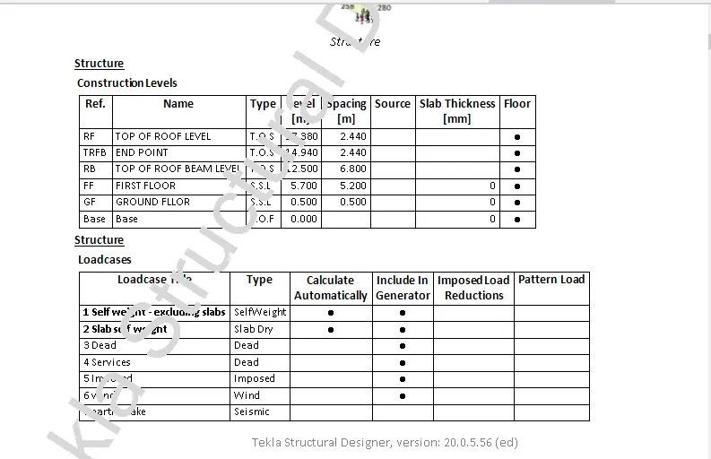
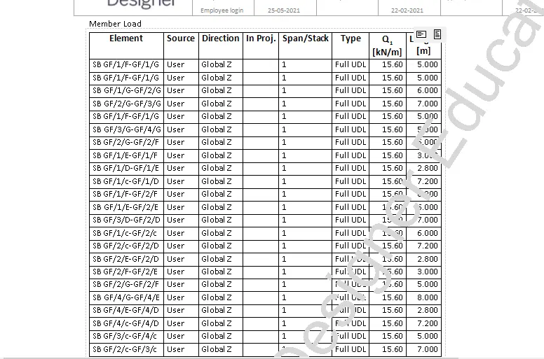
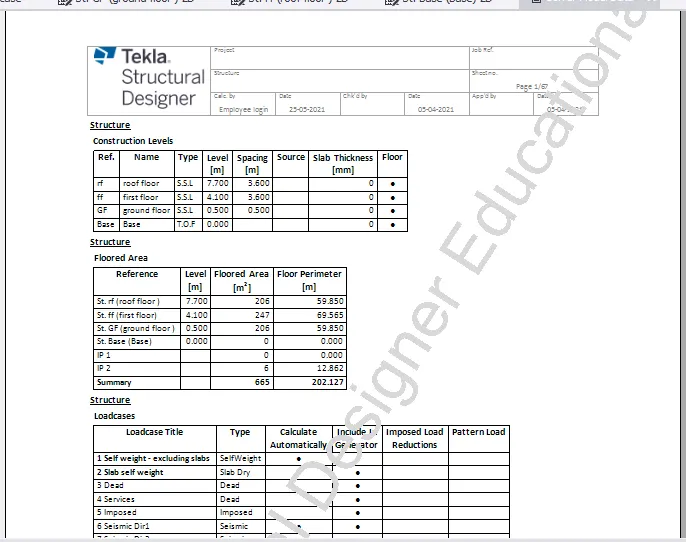
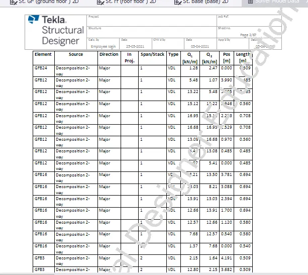
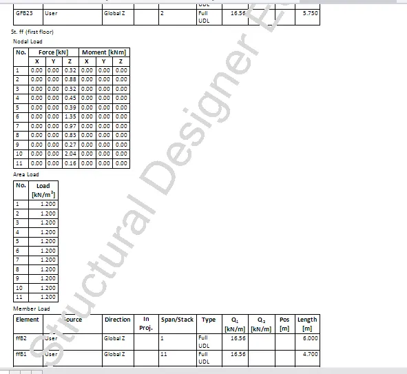
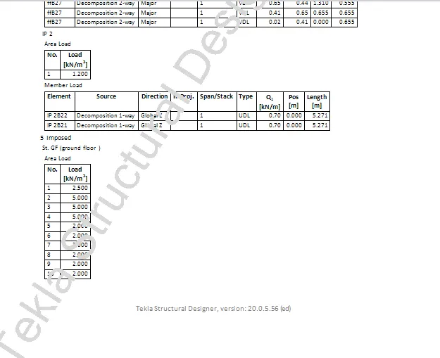
1) Click Show Report
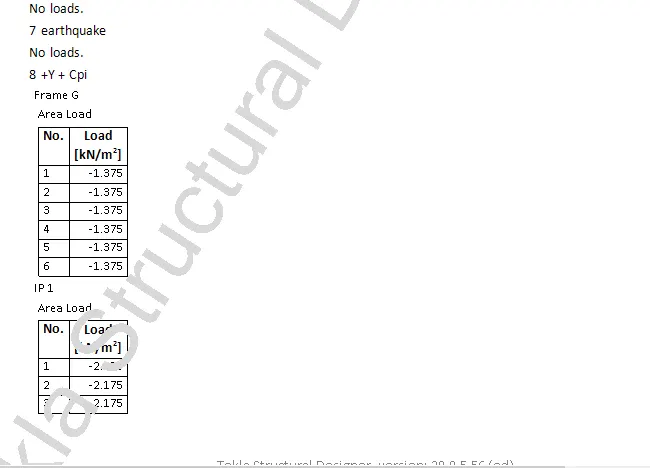
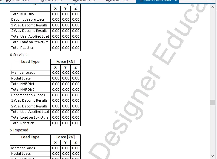
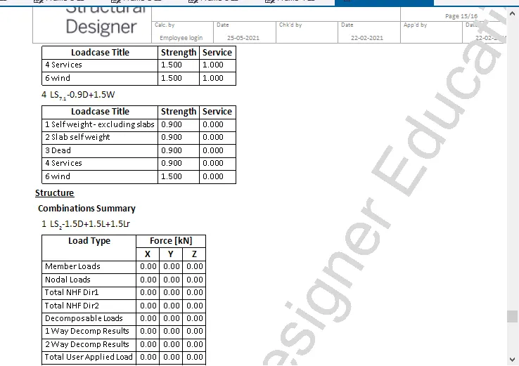
Go to report tab
2) Select the levels, load, loadcase and combination
3) Click ok
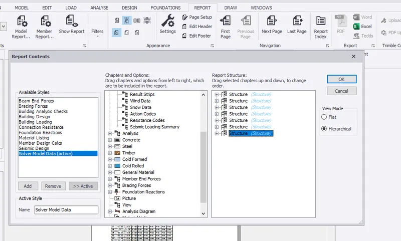
Step 3:
1) Click Show Report
Go to report tab
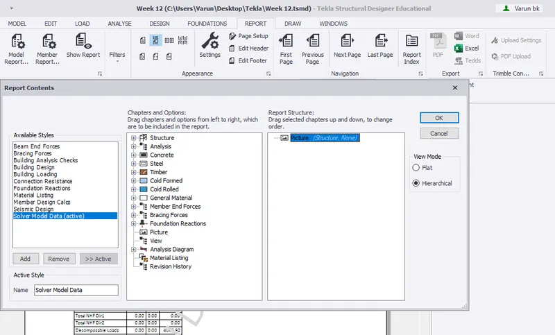
2) Select the Picture
3) Click ok
Step 4:
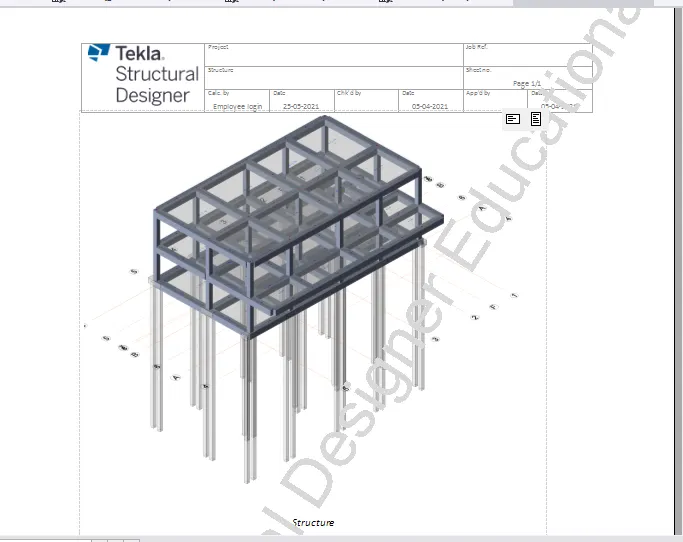
1) Click Show Report
Step 5:
1) Go to report tab
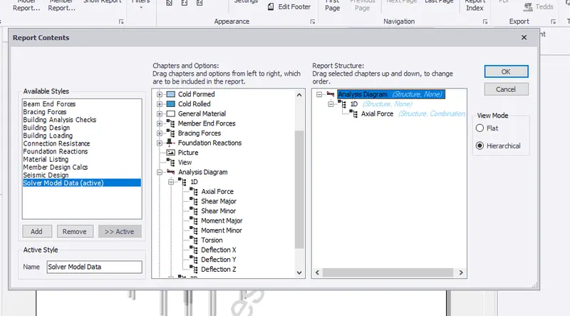
2) Select the Analysis diagram and choose shear force
3) Click ok
Step 6:
1) Click Show Report
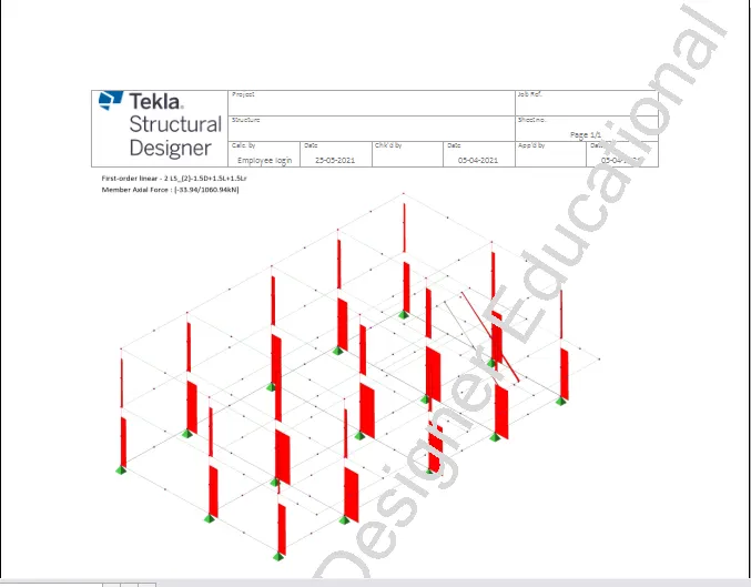
Step 7:
1) Click Show member report and select concrete column
2) Select drawing and shear for the particular member
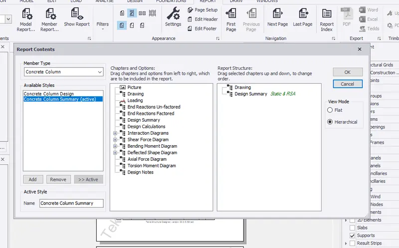
Step 8:
1) Click show report
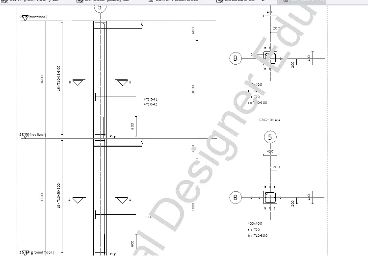
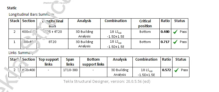
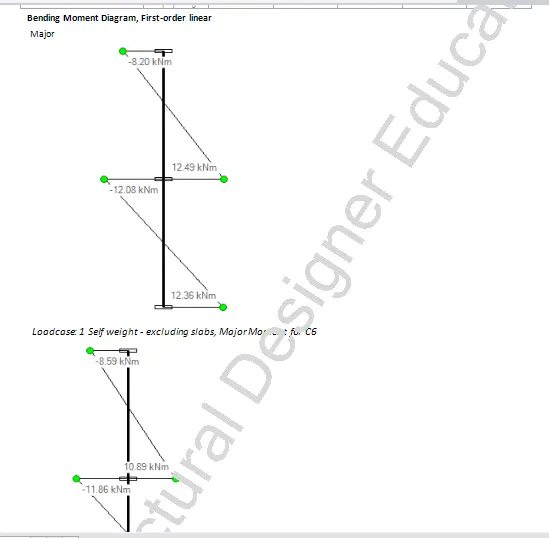
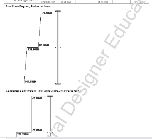
Manage Properties
->Slabs
->Properties tab
->Load
->Load cases
->Dead load
->Area
->Full UDL
->Line
->Validation
Calculations:
DEAD LOAD :
Slab load = Model slab in software.
Finishes loading (50THK) = 0.05m x 24 KN/m^3 = 1.2 KN/m^2.
Brick wall with cement plaster thickness = 150mm.
Unit weight = 20 KN/m^3
Floor height (GF to FF) = 5.2 m
Brick wall loading = 15.6 KN/m
Floor height (FF to Roof) = 6.8 m
Brick wall loading = 20.4 KN/m
Roof loading = 1.5 KN/m^2
Procedure:
- Firstly, open the file which was created earlier.
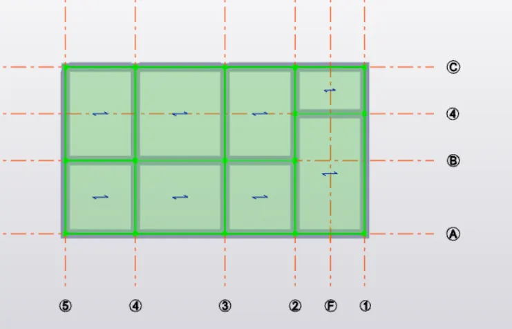
- Go to load tab and select load cases option under that, Load cases dialog box appears.
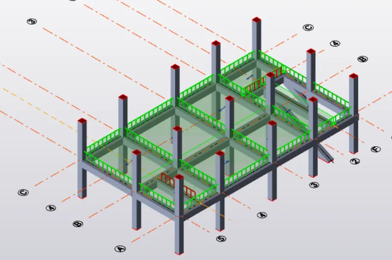
- Under load tab we have to select area and give the value of 1.2KN/m square, and select all the slabs.
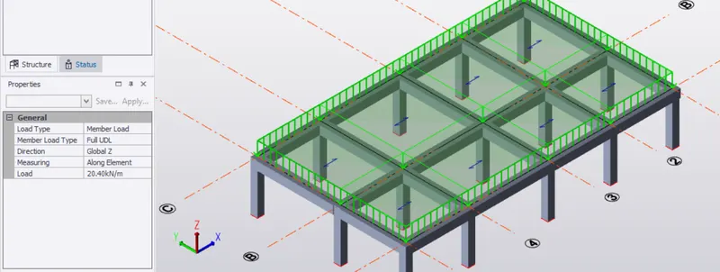
- Now we have to select Full UDL and apply the dead load to all the beams.
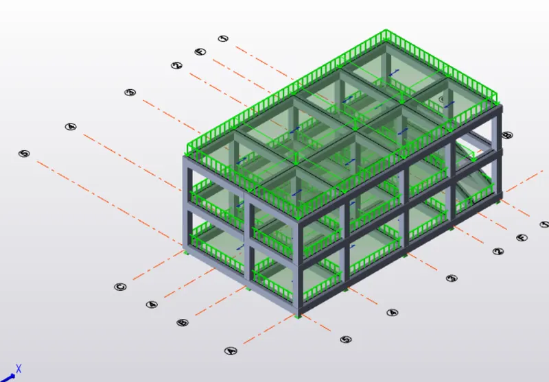
- Now select Line tool under load tab and draw the walls load in all the required floors.
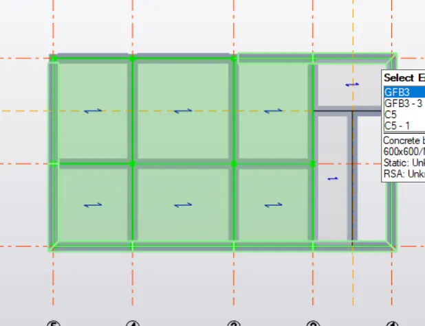
- Also design the staircase with the proper adjustments.
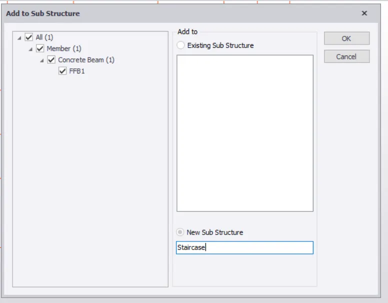
- To create stairs we need to select the components and make them all come under a substructure naming it as staircase.
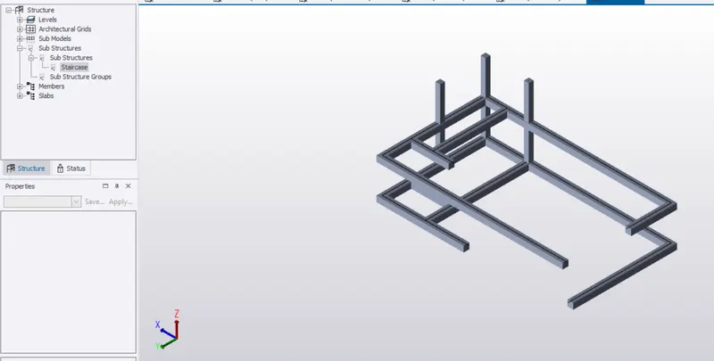
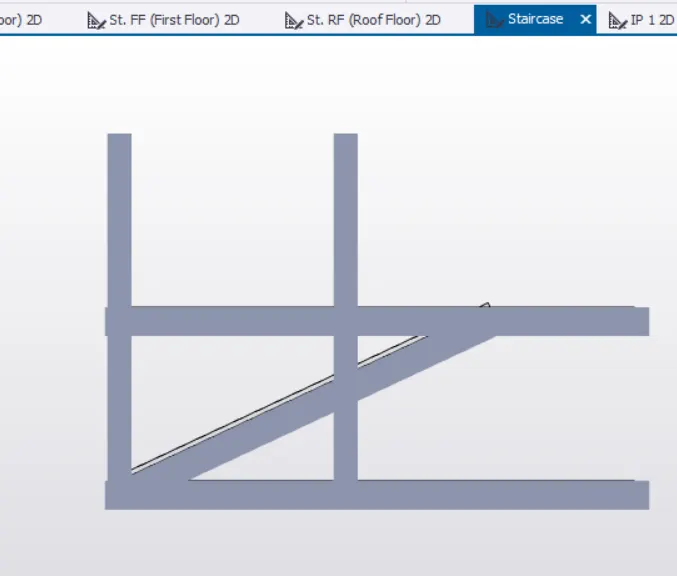
- Now add the slope with the help of sloped plane option.
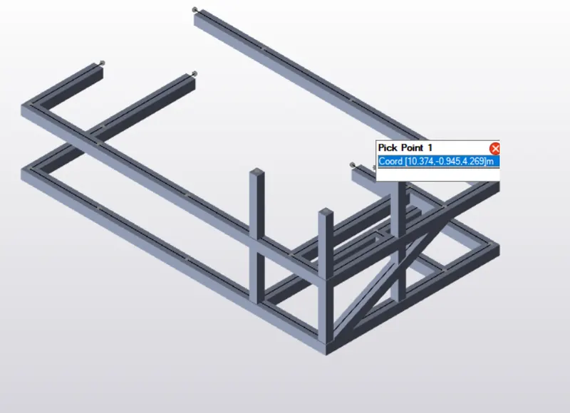
- Now create the slab and area load to the stairs also.
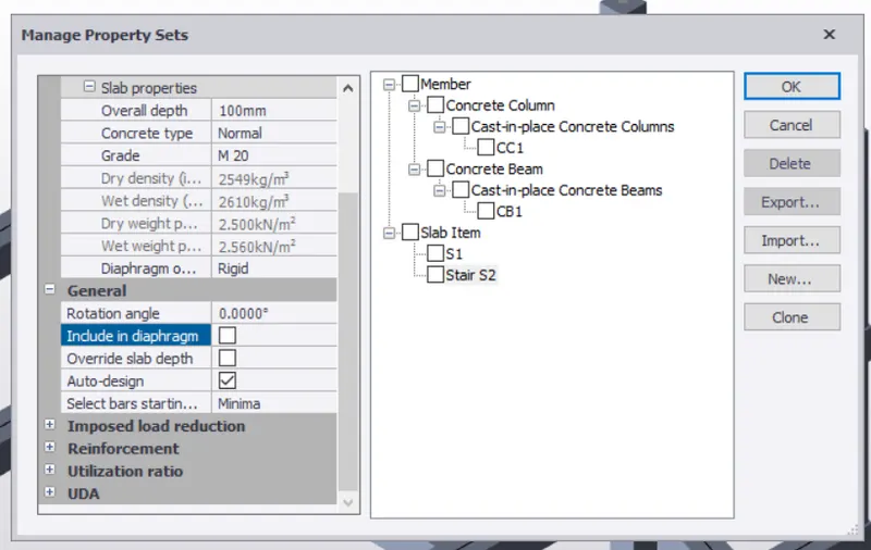
- Do not forget to validate your model every now and then as to check your errors and correct them.
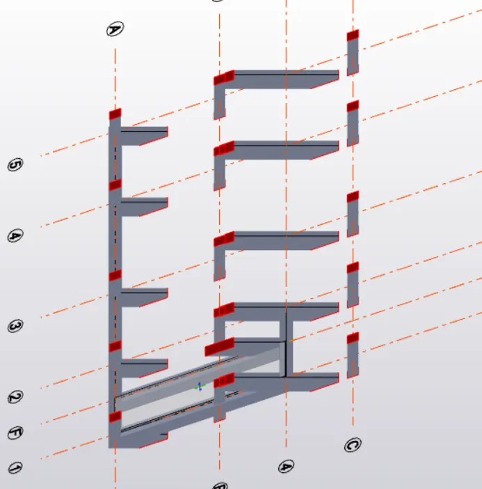
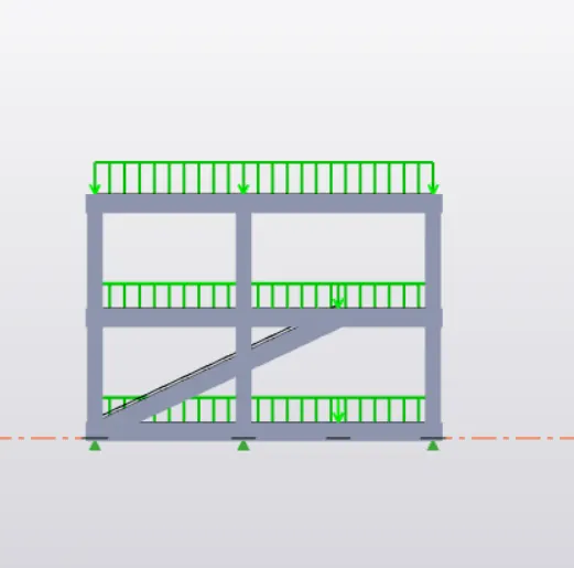
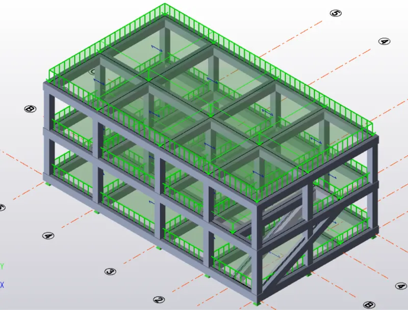
Result:
Hence by following the above procedure we will be able to provide the dead loads to the slabs and beams for structure.
2)
AIM : To generate load summary report for the steel building design
INTRODUCTION : Report commands are accessed from the report ribbon tab where we can customize model and member reports with specific content.
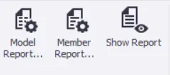
- MODEL REPORT : Create or edit chapters of the model report. Customisation to select particular level, frame, plane and substructure option is also available in model report.
- Example : Structure, Analysis, Loading, Load cases etc
- MEMBER REPORT : Create or edit chapters of the member report
- Example : Diagram and results of SFD, BMD, Deflections etc
- SHOW REPORT : Displays selected style report
PROCEDURE :
- Open steel building model
- First run analysis for the model
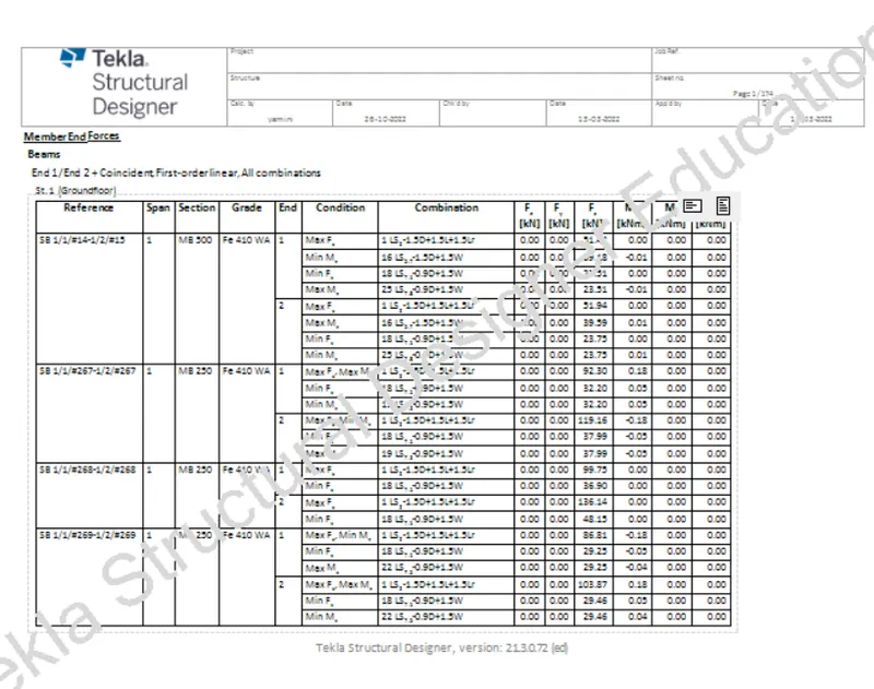
- Then go to report tab and select "Beam end forces"
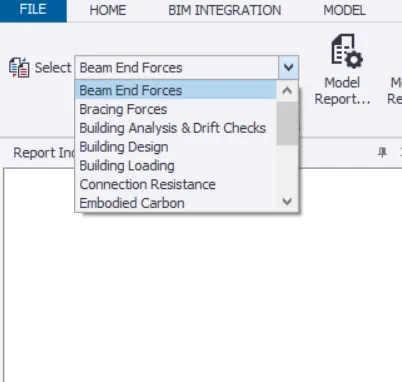
- Click on Model report settings and select necessary content for report generation
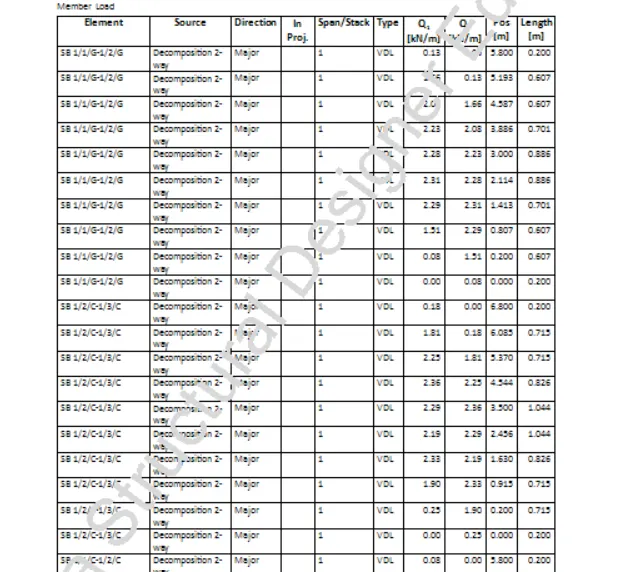
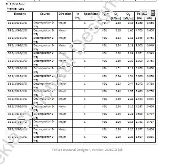
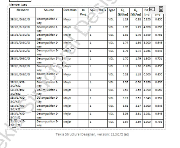
- Example : For Beam end forces, In "Structure"
Select level, loading, loadcase summary, combination and seismic load 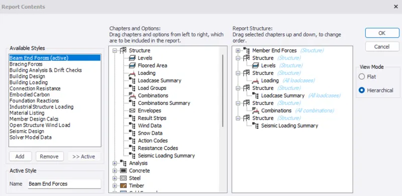
- Example : For Beam end forces, In "Structure"
- Now select Show report
- Similarly generate analysis
- Click on Model report settings and select necessary content for report generation
- Example : For Beam end forces, Analysis
Select element and move it to right side 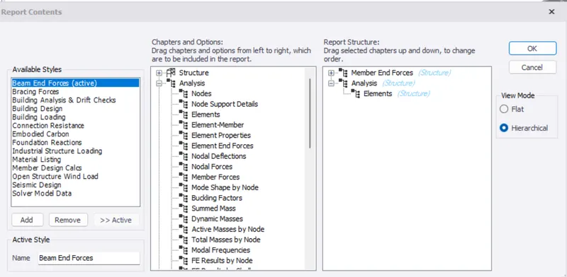
- Right click and select Model Filter
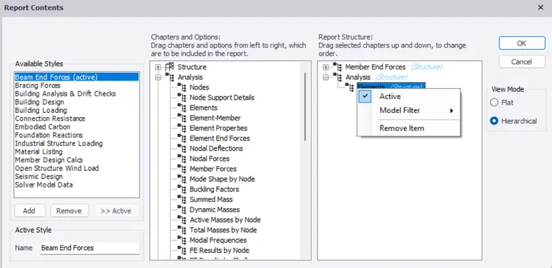
- Select "Edit/New"
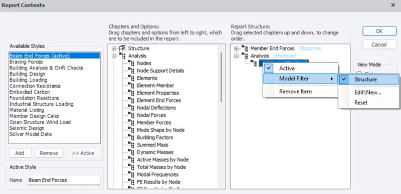
- We get a "Select Filters"
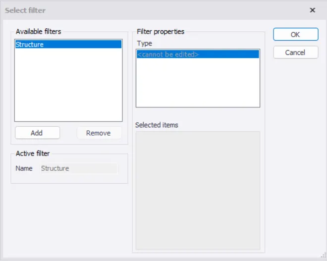
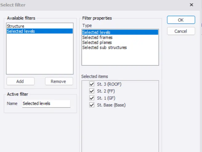
- Select "Add"
- Select the levels and click ok
- Firstly, open the file in which the live loads were added.
-
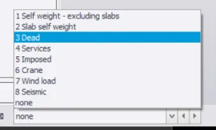
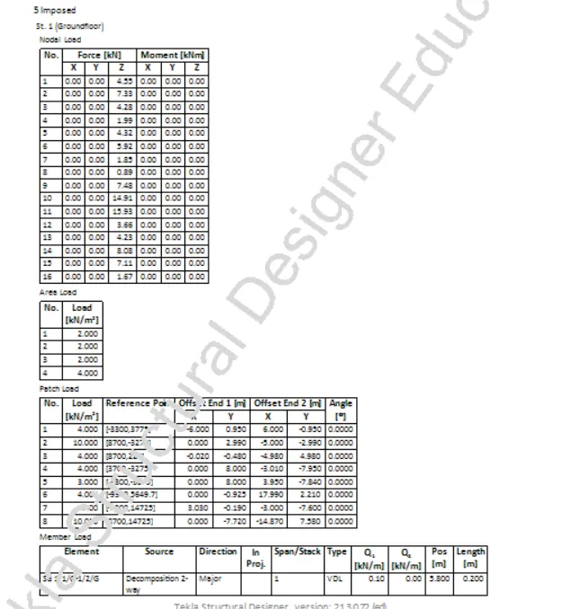
- Now at the bottom of our workspace we find imposed load option in the drop up dialog box.
- Now we can provide live loads to the structure by selecting the load and assigning the value for it according to the IS Code.
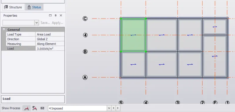
- Click on loads icon and select area option under that.
- The live loads for the structure can be obtained from the IS building standard codes.
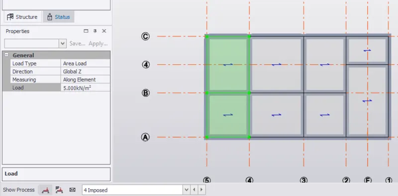
- Now under the property dialog box enter the required load for different room.
Store room = 5 KN/m^2
Office = 3 KN/m^2
Rest room = 2 KN/m^2
Meeting Room = 2 KN/m^2
Toilets = 2 KN/m^2
Pantry = 3 KN/m^2
Corridor = 4 KN/m^2
Equipment room = 10 KN/m^2
- Now set the loads with different values and apply them by clicking on the respective slabs.
- Now repeat the same process for all the remaining levels that is for the first and to top of the roof level.
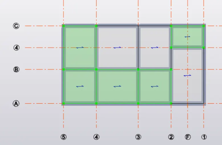
- Do not forget to validate your model every now and then as to check your errors and correct them.
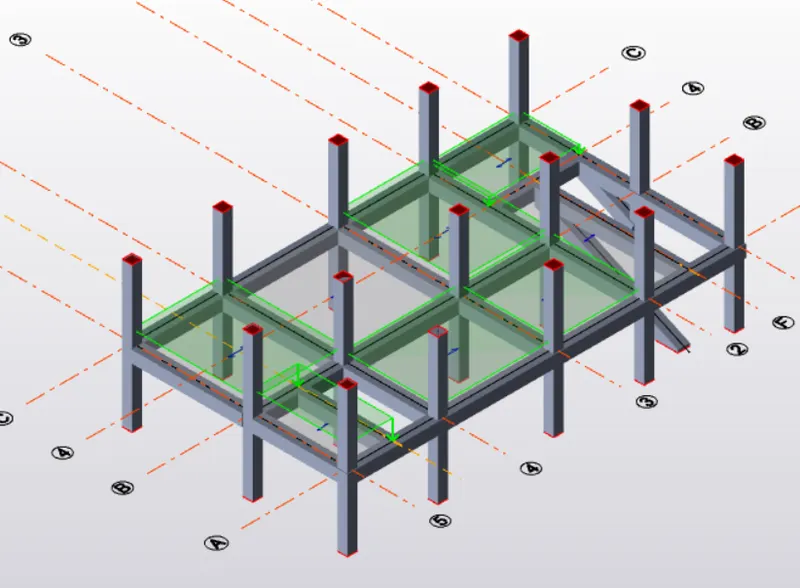
- Example : For Beam end forces, Analysis
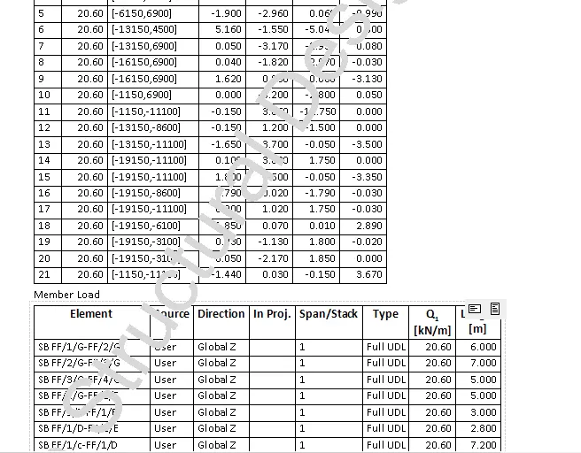
RESULTS : Structure report( For few members)
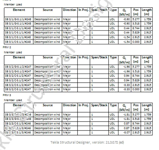
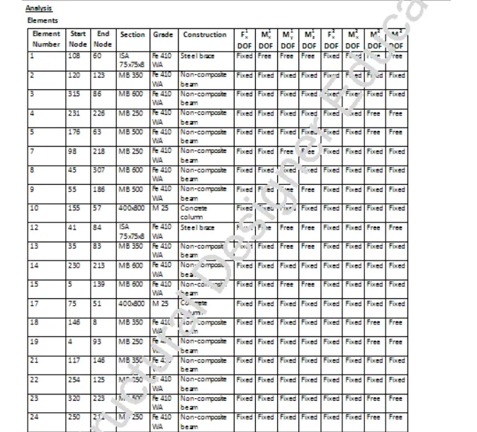
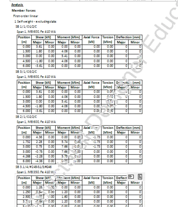
- Analysis report( for few members)
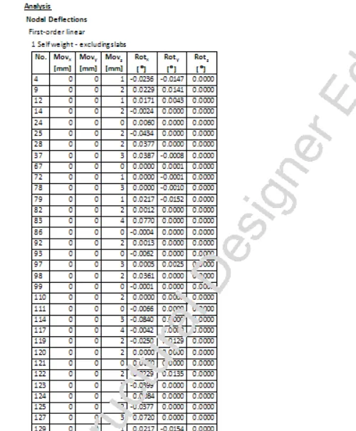
- Nodal deflections
- MEMBER FORCES REPORT
- 3)
- Aim :- The layers settings in the model and generate plan drawings and details from the model
-
Procedure :-
-
Layers are the primary method for organizing the objects in a drawing by function or purpose. Layers can reduce the visual complexity of a drawing and improve display performance by hiding information that you don’t need to see at the moment.
Before you start drawing, create a set of layers that are useful to your work. In a house plan, you might create layers for the foundation, floor plan, doors, fixtures, electrical, and so on.
In this example, the display is limited to the objects on the Floor Plan layer by turning off the other layers.
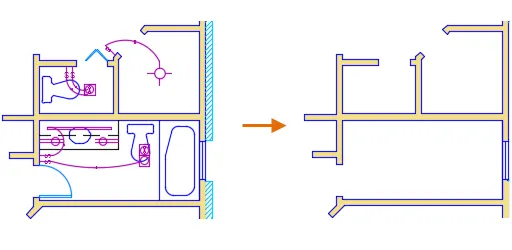
For other disciplines, the names and number of layers that you create will be different. Once you create a standard set of layers, you can save the drawing as a template file (.dwt) that you can use when you start a new drawing.
For complex drawings, you might want to consider a more elaborate layer naming standard. For example, layer names could begin with 3 digits followed by a naming code that accommodates multiple floors in a building, project numbers, sets of survey and property data, and so on. This type of naming convention also makes it easy to control the order of the layers and limit the layers displayed in the layer list.
Layer Tools
Use the Layer Properties Manager to manage your layers. Find
- Create, rename, and remove layers
- Set the current layer on which new objects are automatically created
- Specify the default properties for objects on the layer
- Set whether the objects on a layer are displayed or turned off
- Control whether objects on a layer are plotted
- Set whether a layer is locked against editing
- Control the layer display properties for layout viewports
- Sort, filter, and group layer names
Note: You can override any layer property of an object. For example, if an object’s color property is set to BYLAYER, the object displays the color of that layer. If the object’s color is set to Red, the object displays as red, regardless of the color assigned to that layer.In addition to the Layer Properties Manager, you can access layer tools on the Layers panel on the Home tab of the ribbon.
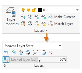
For example, the Off button turns off the layers of any objects that you select.
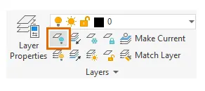
Current Layer
All new objects are drawn on the current layer by default. The green check mark on the Layer Properties Manager indicates the current layer.
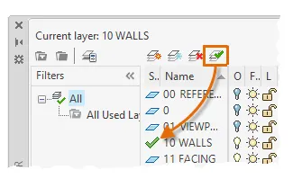
A layer cannot be the current layer if:
- The layer is frozen
- The layer is part of an external reference
For certain types of objects, you can specify a default layer other than the current layer by setting a system variable. These include the following objects:
- Dimension objects: DIMLAYER system variable
- Text and Mtext objects: TEXTLAYER system variable (added in the 2020.1 update)
- Hatch objects: HPLAYER system variable
- Centerline objects: CENTERLAYER system variable
- Center Mark objects: CENTERLAYER system variable
- Converted SHX text from imported PDF files: PDFSHXLAYER system variable
Layer Visibility
You can control the visibility of objects on a layer by toggling the layer on/off or by using freeze/thaw.

 You can turn layers off and on as needed. Objects on layers turned off are invisible in the drawing.
 Freezing and thawing layers is similar to turning them off and on. However, when working with drawings with lots of layers, freezing unneeded layers can speed up display and regeneration. For example, objects on a frozen layer are not considered during a ZOOM EXTENTS.
Locking Layers
You can prevent objects on selected layers from being inadvertently modified by locking those layers. By default, objects on locked layers appear faded and a small lock icon is displayed when you hover over the object.
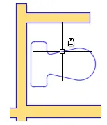
You can set the fade level for locked layers or hide them. Find
The fading feature for locked layers lets you reduce the visual complexity of a drawing, but still maintain visual reference and object snapping capabilities.
In this example, the fading level is set at the fading levels of 90%, 50%, and 25%.
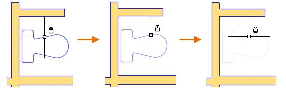
There are a few things to keep in mind when working with locked layers:
- The locked layer fading value further reduces the visibility of transparent objects.
- The locked layer fading value does not affect how objects appear when plotted.
- Grips are not displayed on objects that are on locked layers.
Alternatively, you can hide the objects on locked layers instead of fading them.
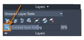
This is a fast way of turning the fading level to 0% and back to the previous level. If you're not using the ribbon, use the LAYISO command.
Layer Filters
Sometimes drawings can include dozens or even hundreds of layers. A layer filter limits the display of layer names in the Layer Properties Manager and in the Layer control on the ribbon. You can create layer property filters based on the name, color, and other properties. For example, you can define a property filter that lists all layers that include the letters "mech" in the layer name and are set to red.
You can also create layer group filters where you choose specific layers to include in the group. For example, you could create a group called Tool Fixture that includes all the layers associated with the tool fixtures in your drawing. When you click the Tool Fixture group in the Layer Properties Manager, only the layers in the Tool Fixtures group are listed.
Override the Current Layer by Object Type
By default, all new objects are created on the current layer. For some types of objects, you can specify a default layer based on the object type rather than the current layer. For example, if you want all dimension objects to be created on a layer named 040 Dim, set the DIMLAYER system variable to 040 Dim. All subsequently created dimensions are then automatically assigned to that layer.
The object types that can be set include the following:
- Centerlines - CENTERLAYER system variable
- Hatches - HPLAYER system variable
- Dimensions - DIMLAYER system variable
- Text and multiline text - TEXTLAYER system variable
- Xrefs - XREFLAYER system variable
- Check the numbering settings by going to the Drawings & reports tab and clicking Numbering settings > Numbering settings.
- Select Compare to old for both the new and modified parts.
- Number all model objects that have same numbering series settings on the Drawings & reports tab by clicking Perform numbering > Number series of selected objects, or number only new or modified model objects by clicking Perform numbering > Number modified objects.
- Check the Document manager for status flags.
- To find the parts that have been affected, select each drawing marked with the flag in the Document manager and click the Select objects button.
Tekla Structures highlights the affected parts in the model.
Do the following:
- Check the numbering history log for renumbered parts by going to the File menu and clicking Logs > Numbering history log.
-
Layers can also be used when importing or exporting .dwgs/.dxfs. When importing a .dwg, you can see all of the custom layers used in SOLIDWORKS or another 2D application.
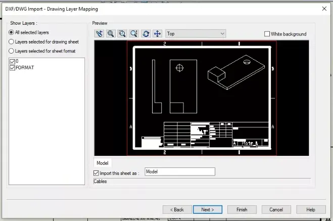
Figure 1: Import layer options
Layers in SOLIDWORKS have more functionality than that. If you right-click your CommandManager and select the Layers option, it will turn on the Layers toolbar. You will see this in the bottom left-hand side of the screen.
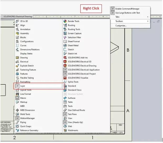
Figure 2: Activating Layer menu
By default, you will have three choices:
- -Per standard- will reference the document properties.
- -None- is general and references the system options.
- FORMAT is everything on the sheet format.
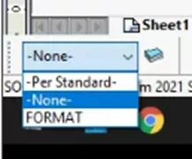
Figure 3: Default layer options
Layers can be used in SOLIDWORKS to create specific types of annotations. In this example, we are making one for center marks. To do this, click the Layers button to display the Layers menu.
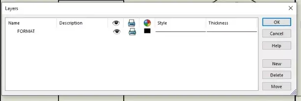
Figure 4 : Layers menu
Click New to add a new layer and give it a name. You can change different options for the items on this layer, such as color, style, and thickness. You can also turn layers on and off to show only the ones you want. For this example, we are going to change the color to red. Click OK when finished to accept this new layer.
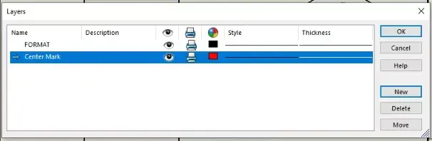
Figure 5: Center Mark layer
In the bottom left-hand side of SOLIDWORKS, you can see the active layer is the newly created layer. This means that after making a new layer, every new annotation you add to this sheet will be on this layer.
If this is not what you intended, you can change it back to -None-. To add annotations to a layer, right-click on the annotation and select Change Layer.
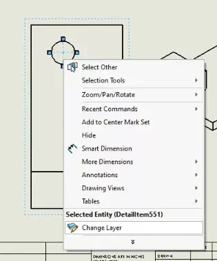
Figure 6 : Change Layer
A drop-down will appear allowing you to choose the layer you want it to be moved to. In this example, the center marks are now red, matching the layer they are on.
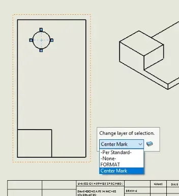
Figure 7: Center Mark layer
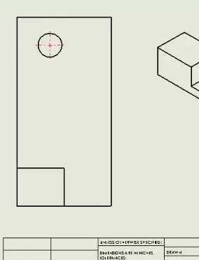
Figure 8 : Red Center Mark
This workflow is manual and a bit tedious. Another option is a bit more automated, and that is the -per standard- option; you will never have to do it again after the initial setup.
To do so, go to Tools > Option > Document Properties .
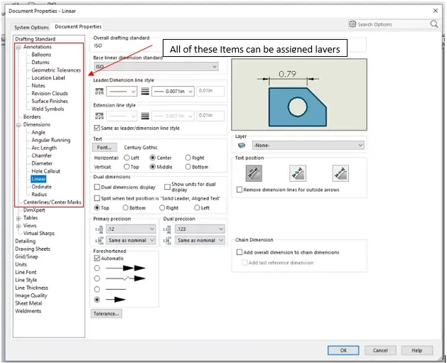
- Result :- The layers settings in the model and generate plan drawings and details from the model