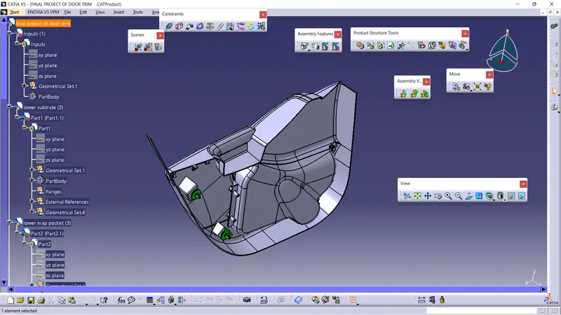
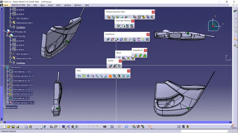
to develop a door trim panel
AIM:To develop a door trim panel following the design guidelines.
SOFTWARE USED: Catia V5.
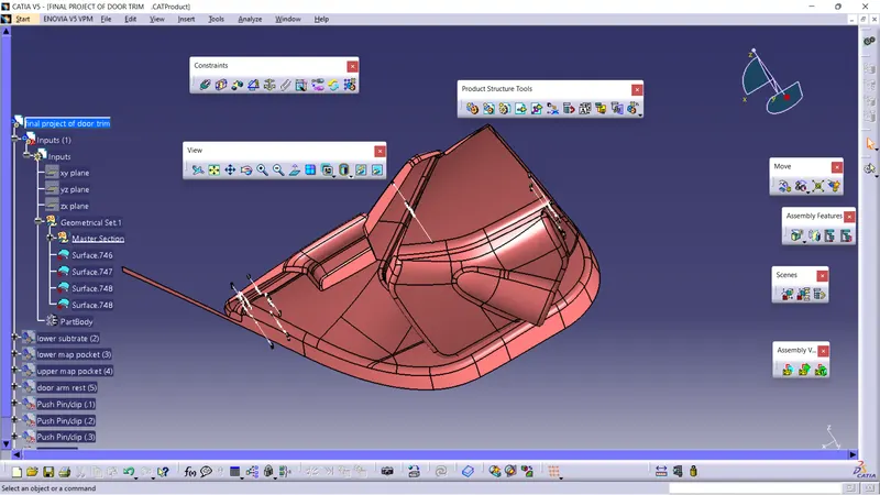
INTRODUCTION:
Door panels serve as an interface between the interior of the car and the inner workings of the door, and between vehicle occupants and the door. They are expected to meet a variety of design specifications regarding safety, aesthetics, and functionality. In addition, they are expected to continue the material theme of the dashboard and pillars while concealing intricate electrical and mechanical components for operating locks, windows, and other features. The door panel has evolved from a simple two-part system of latch and simple winding mechanism to a more sophisticated enclosure. Doors currently have an inner full-width panel consisting of electronic windows, central locking system, and speakers. These panels typically consist of a foamed core covered with either textiles or plastics.
DOOR TRIM PANEL CONSISTS OF FOLLOWING COMPONENTS:
1.DOOR ARM REST
2.UPPER MAP POCKET
3.LOWER MAP POCKET
4.LOWER SUBSTRATE
5.UPPER SUBSTRATE
6.FLANGES
8.HEAT STAKES AND DOG HOUSE
1.DOOR ARM REST
In the front of the car, a central armrest, which commonly folds away based on user preference, will also often include a storage compartment and sometimes even cup holders. Some also provide the location for controls for non-essential functions of the vehicle, such as climate control or window motors.
CLASS A SURACE:
CLASS A refers to those surfaces which are VISIBLE and abide to the physical meaning, in a product. This classification is primarily used in the automotive and increasingly in consumer goods (toothbrushes, PalmPC's, mobile phones, washing machines, toilet lids etc.).
‘A' Class surfacing and its importance: A class surfaces are those aesthetic/ free form surfaces, which
are visible to us (interior/exterior), having an optimal aesthetic shape and high surface quality.
Mathematically class A surface are those surfaces which are curvature continuous while providing
the simplest mathematical representation needed for the desired shape/form and does not have
any undesirable waviness. Products are not only designed considering the functionality but special
consideration is given to its form/aesthetics which can bring a desire in one’s mind to own that
product. This is only possible with high-class finish and good forms. This is the reason why in design
industries Class A surface are given more importance.
In automotive design, a class A surface is any of a set of freeform surfaces of high efficiency and
quality. Although, strictly, it is nothing more than saying the surfaces have curvature and tangency
alignment – to ideal aesthetical reflection quality, many people interpret class A surfaces to have G2
(or even G3) curvature continuity to one another (see free form surface modelling). Class A surfacing
is done using computer-aided industrial design applications. Class A surface modelers are also called
"digital sculptors" in the industry. Industrial designers develop their design styling through the ASurface, the physical surface the end user can feel, touch, see etc.
Class A is
1.Visible surface and aesthetic look
2.surface with textures
3.Surfaces provided by customer(OEM)
4.Don't have any features like(rib,snap,bosses etc) on class A surface.
5.Class A surface is made from scanned data with different software like allias etc..
C SURFACE:
Class C surfaces are the backside surfaces that can have tool marks, flash and other imperfections without hurting appearance, function, etc.
Class C surface is normally created using the sweep command.
First the boundary is extracted and it is made smooth using curve smooth command and then it is
sweeped by giving 0.5 draft outwards.
Normally the C surface is nothing but adding thickness or filling the gap between the A surface and B
surface.
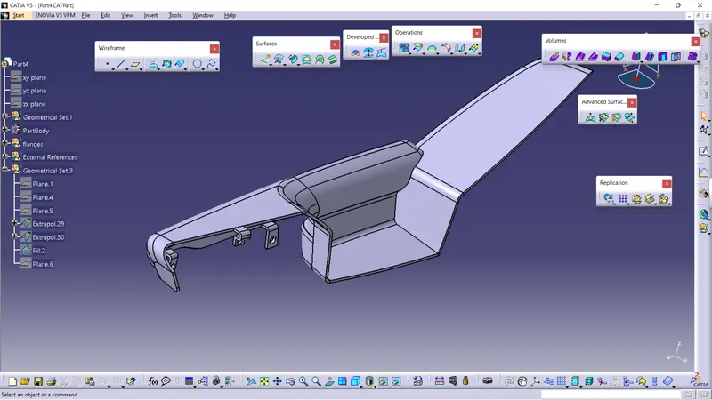
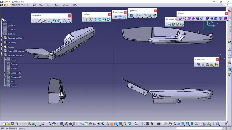
2.LOWER SUBSTRATE
CLASS A SURFACE
CLASS B SURFACE:
B surface is created by offsetting A surface by 2.5mm
C SURFACE:
C surface is created by extracting the boundary of A surface and using the sweep command.
COMMANDS USED:
1.EXTRACT AND MULTIPLE EXTRACT.
2.BOUNDARY
3.SWEEP
4.SPLIT
5.BLEND
6.MULTI SECTION
7.TRIM
8.JOIN
a)After creating the C SURFACE then join it with A SURFACE.
b)Then trim the joined A SURFACE AND C SURFACE with extrapolated B SURFACE
c)Then check for the gaps using boundary command and try to solve the gaps
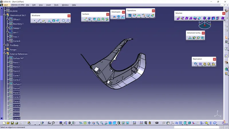
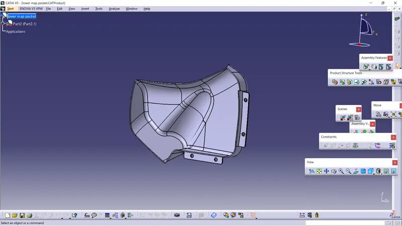
3.MAP POCKET
a)LOWER MAP POCKET
Map pockets can be created integrally within the door trim panel by forming a projection region outwardly towards the passenger compartment and then providing a separate panel attached to the rear outboard surface of the trim panel. This type of map pocket protrudes into the passenger compartment. Another type of map pocket such as a recessed map pocket can also be formed within the door assembly such that the storage compartment of the map pocket is generally located between the trim panel and the outer metal panel of the vehicle door. An aperture in the door trim panel defines the opening into the map pocket. Generally, these types of map pockets are formed by a separate map pocket assembly which is fastened to the rear surface of the trim panel. The map pocket assembly includes a front portion and a separate rear portion which are connected together to form the map pocket assembly and define the storage compartment. The rear portion defines a rear wall of the map pocket assembly. The front portion defines a lower front wall and a pair of side walls. The region above the lower front wall is generally open to provide access to the storage compartment of the map pocket. The map pocket assembly is then attached to the rear surface of the door trim panel such that the opening of the map pocket is generally aligned with an opening formed in the door trim panel.
CLASS A SURFACE:
Class A surface is provided by the industry we need to create B SURFACE and C SURFACE according to A SURFACE provided.
4)UPPER MAP POCKET
CLASS A SURFACE:
CLASS B SURFACE:
CLASS C SURFACE:
TRIM A SURFACE B SURFACE AND C SURFACE TO OBTAIN THE FINAL BODY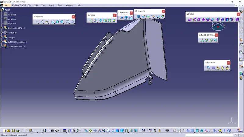
DOG HOUSE:
Dog house is an engineering feature used in plastic trim design. Dog houses are used as supporting feature. Sometimes other engineering features like snaps; locators etc. are mounded on them to increase their strength. Dog houses are subjected to draft analysis to prevent breakage of the component during ejection from mould cavity. Dog house and other engineering components are built on B-surface.
DESIGN CONSIDERATION FOR PLASTICS:
1.WALL THICKNESS:
Thick sections waste material and are simply uneconomic. So solid shapes that would do the job well in wood or metal must be transformed to a 'shell' form in plastics. This is done by hollowing out or 'coring' thick parts so you are left with a component which regardless of complexity is composed essentially of relatively thin walls joined by curves, angles, corners, ribs, steps and offsets. As far as possible, all these walls should be the same thickness. Wall thickness guide range is 0.75 mm to 3mm for reinforced materials 0.5 mm to 5 mm for unreinforced materials.
WALL THICKNESS(W)=0.70*(NOMINAL THICKNESS OF PLASTIC MATERIAL)
2.CORNER RADII
Properly designed corners will make a big difference to the quality, strength and dimensional accuracy of a moulding. But there is another benefit too. Smooth curved corners help plastic flow in the mould by reducing pressure drops in the cavity and minimising flow-front break-up. Internal radii should be at least 0.5 and preferably 0.6 to 0.75 times the wall thickness.
CORNER RADII= (0.6-0.75) * (NOMINAL THICKNESS OF PLASTIC MATERIAL)
3.DRAFT ANGLE:
Tooling must be cleared for easy ejection of the component, from the core cavity. In order to clear tooling certain value of draft is given to the component. Minimum of 2-3deg is provides on all plastic components.
DRAFT ANGLE=2-3 DEGREE
4.FILLETS:
Fillet on the inner side = 0.25 * Thickness of the plastic material
Fillet on the outer side = 1.25 * Thickness of the plastic material
Fillet on the coring edges = 0.25 * Thickness of the plastic material
Coring thickness = 0.40 * Thickness of the plastic material
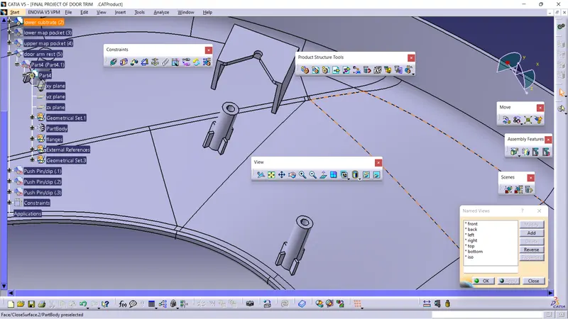
push pin
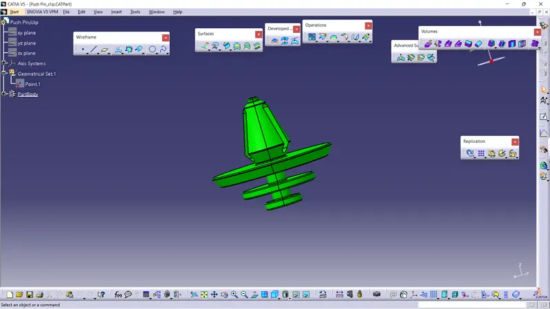
final body