Final Assemble of butterfly value
Aim :- To model and assemble Butterfly Valve and apply GD&T to the butterfly Valve.
Introduction:-
A butterfly valve is a type of valve used to control or isolate fluid flow. An rotating disc acts as the closing mechanism.
A butterfly valve belongs to the quarter-turn valve family of valves. When the disc is turned a quarter turn, the valve is fully open or closed in operation. A metal disc that is mounted on a rod is the "butterfly." The disc is rotated to completely block the channel when the valve is closed. The valve is spun a quarter turn once it is fully opened to allow the fluid to flow practically unhindered. To reduce flow, the valve can also be opened a little at a time.
Procedure:-
For modeling and assembly of butterfly valve different parts of butterfly valve was designed such as
Body
Shaft
Disc plate
Retainer
Lever
Nut
Screw
Various Commands were utilised to model the aforementioned components, including
Sketch is a tool used to create 2D drawings that are then used to create 3D models.
Extrude: To create a solid feature, it extrudes the sketch or a set of sketch contours in one or more directions.
Create holes on the model by using the Hole feature.
Unite is a mathematical operation that unites two or more solid bodies into a single solid entity.
Revolve: To generate a solid feature, it revolves a drawing or a set of sketch contours around an axis.
Chamfer: Using an inclination line, chamfer joins two neighbouring faces.
Overview of parts of Butterfly valve:
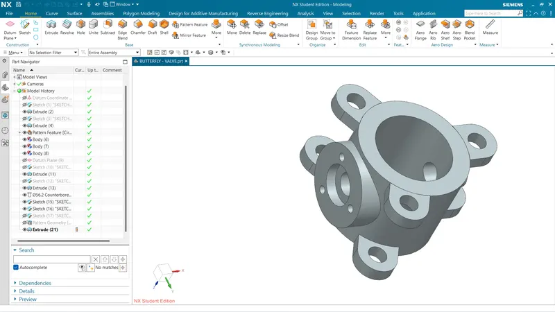
Initially, the sketch for the butterfly valve's body is created in NX CAD using the sketching tools.
Following the extrusion of that sketch, the butterfly valve's ears are drawn and duplicated on both sides of the cylindrical part.
Using the datum plane option, a new plane is now produced on the surface of the cylinder, and a cylinder is created on that plane. then a counter bore is made on that cylinderical surface using the Hole command.
The portion is then preserved after three holes are made for installing the body.
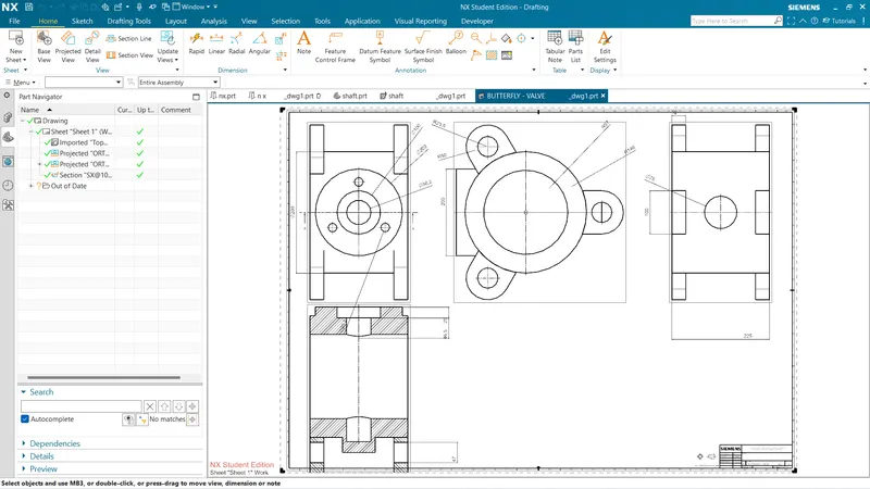
1] Body of butterfly valve
2] Shaft
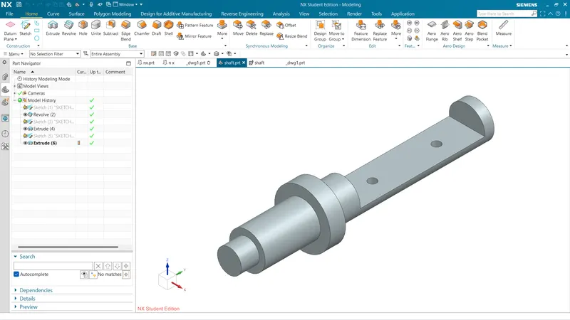
Sketch is created on a plane then, Revolve command is used to get the desired shape of the shaft.
Then Extrude command is used to create a recess portion in the front and rear portion of the shaft.
Finally, two holes of 12.5mm diameter is created in the rear recess portion of the shaft.
Drafting of shaft:
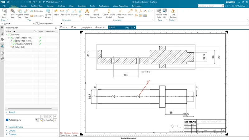
A1 size of sheet is used create drawing of shaft.
Here, only two datums are used as one degree of freedom is required for efficient working of the shaft.
Datum A1 and A2 is given to the part which comes in contact with the body of butterfly valve.
Datum B is given to the base of the shaft.
Different tolerances are given to some features which are important for functioning of the shaft.
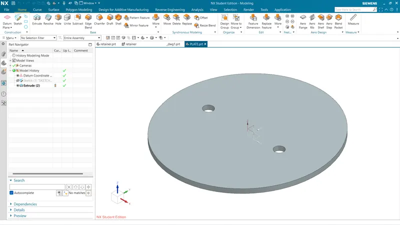
3] Plate
2D sketch is drawn on a plane.
Then the sketch is Extruded to create plate
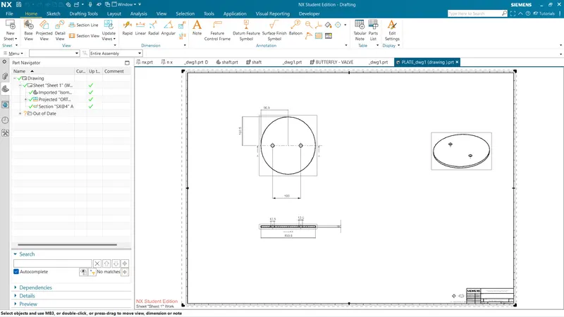
Drafting of Disc plate
Datum target areas A1 and A2 is given to the side of the disc which is going to come in the contact with shaft.
This two datum target area A1 and A2 forms datum A.
Datum B is given to the one hole on the disc plate and Datum C is given to the other hole.
Then, the tolerances are given to the surface and features of the Disc plate.
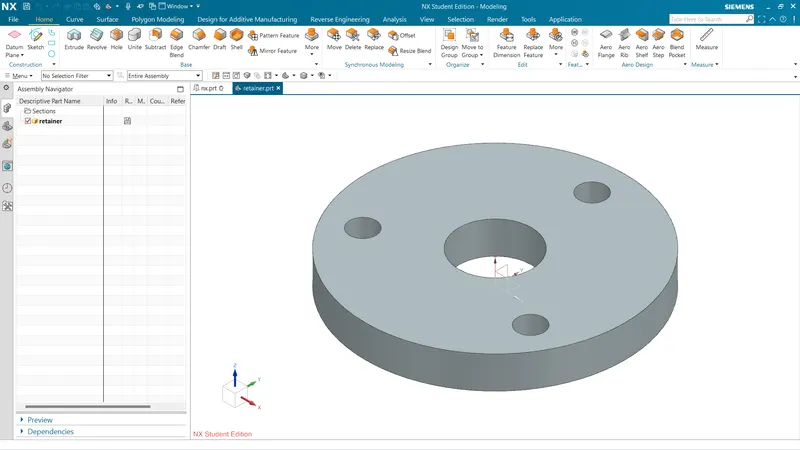
4] Retainer
2D sketch is drawn on a plane.
Then the sketch is Extruded to create a Retainer.
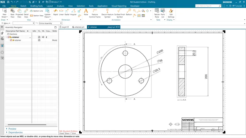
Drafting of Retainer
After modeling, drafting tool is used to create a drwaing of retainer on A1 size drawing sheet.
Datum target area A1,A2 and A3 is given to the surface which comes in the contact with the upper surface of body.
Datum B is applied to the one of the holes of retainer where the screw is inserted.
Datum C is applied to the other hole.
Finally, other tolerances are applied to the surfaces and features of retainer.
5] Lever
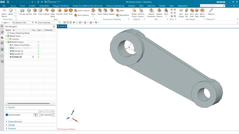
2d sketch is created on plane with the provided dimensions.
sketch is then Extruded to create Lever.
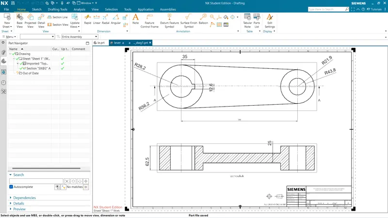
Drafting of Lever
Datum A is given to bottom surface which comes in contact with retainer.
Datum B is given to the hole where the bolt is to be inserted.
Datum C is given to the other hole to complete the constraint the part.
Finally, other tolerances are applied to the surfaces and features of Lever.
6] Nut
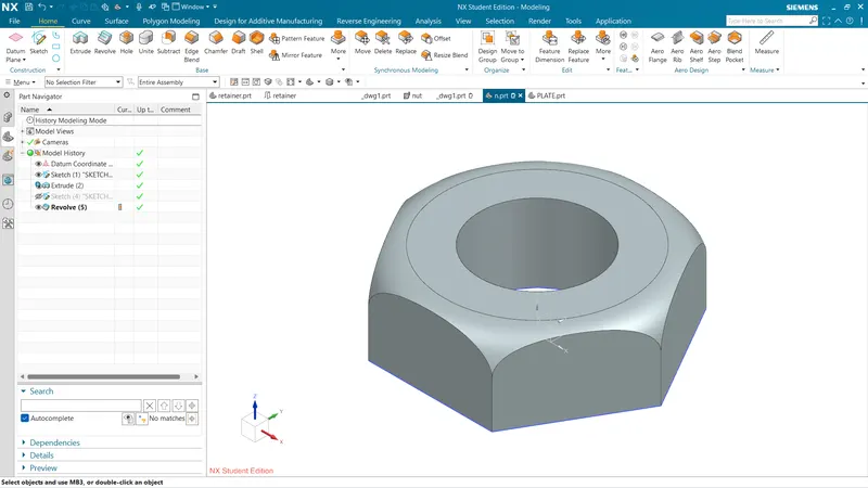
A hexagon is created on the plane and is then extruded to get desired solid body.
Another sketch is created on XZ plane, Sketch fillet is used to create a arc which will gives smooth curve to the upper surface of Nut.
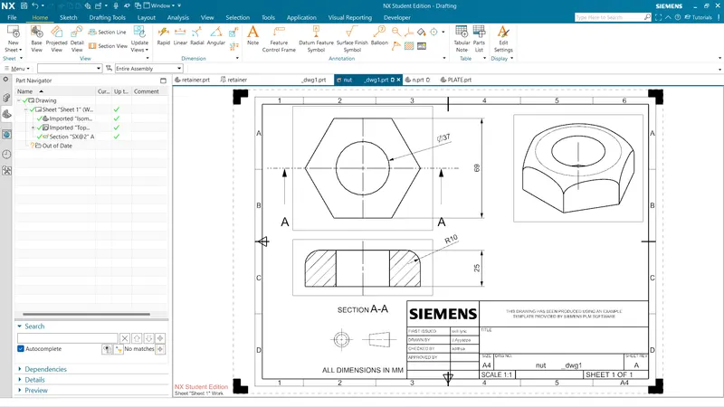
Drafting of Nut
Datum A is given to the bottom surface of Nut which is going to come in contact with Lever surface.
Datum B is given to the Hole.
Finally, other tolerances are given to the surfaces and feature of Nut.
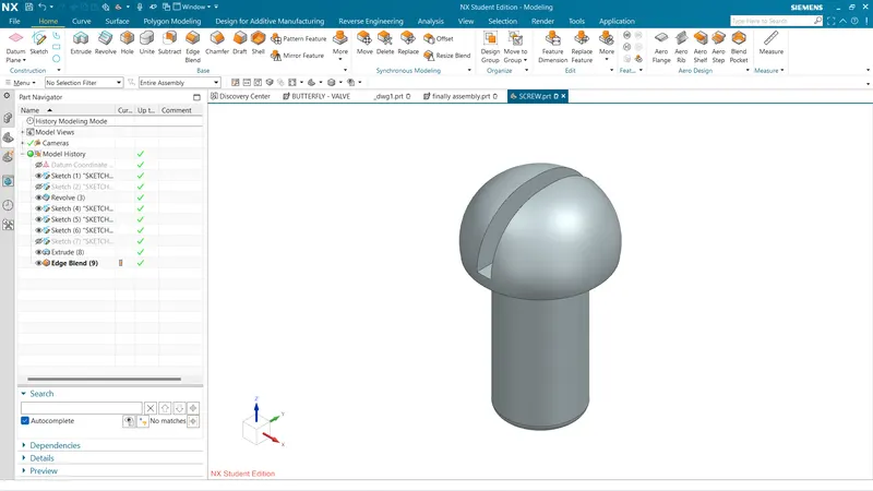
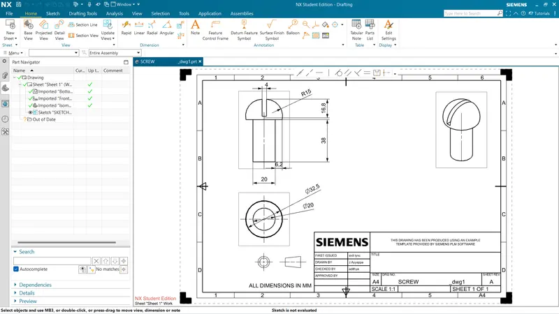
7] Screw
2D sketch is created on a plane as per the given dimensions.
Then, revolve command is used to create a screw and the part is saved.
8] Assembly of Butterfly Valve
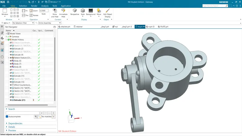
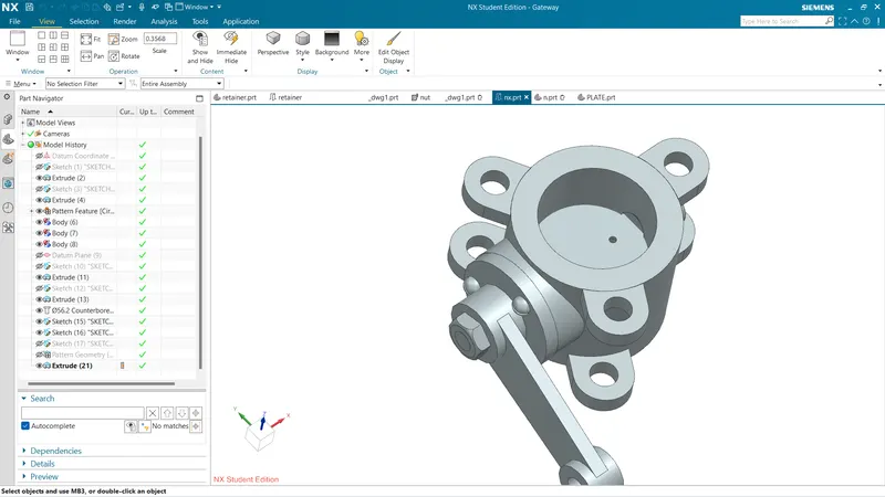
Assembly file is opened in NX CAD.
Above parts are added in the assembly file.
Now, one by one parts are assembled using Move part command and assembly constraint command.
Different constraints are used to assemble butterfly valve, such contraints are: Infer Axis, Touch, Align.
Finally, assembly of BUtterfly vlave is saved in the folder where all the other parts are saved.
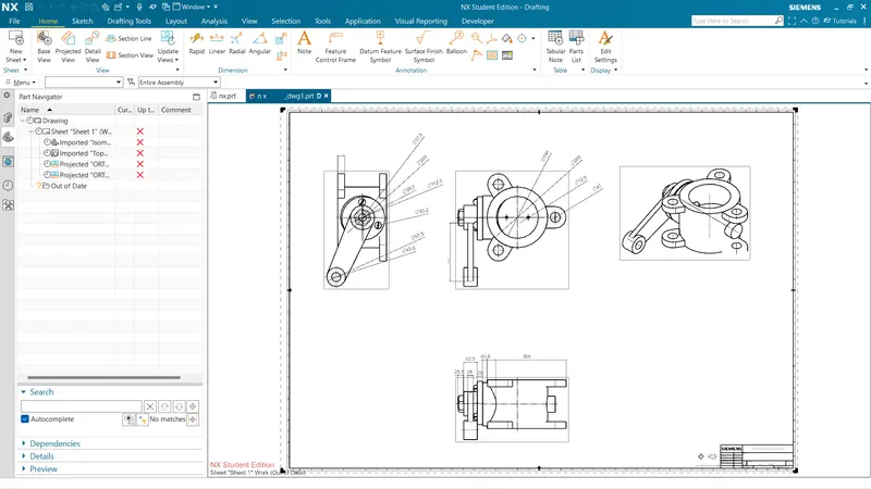
Drafting of Assembly
Datum target area A1,A2 and A3 is given to the ears of the butterfly valve.
Datum target area A2 and A3 is given with perpendicular tolerance and Position tolerance respectively.
Sub datum D is given to the thrid ear.
Finally, other tolerances are given to the surfaces and features of the Butterfly Valve.
Conclusion:-
Designing and Modelling and drafting of different parts and assembly of Butterfly Valve is completed.