To calculate the dead , live and wind load for RC residential structure and to apply them using TSD
- Calculate dead load in design report based on IS code and apply dead load on the model
- Finishes of 50mm
- Slab thickness as per the design
- Brick wall load
- Roofing load
AIM:- To calcuate dead laod in design based on IS code and apply on model.
Tools Used- Load cases, Full UDL, Area Load , Property Window.
Calculation-
Slab load = (Model Slab In software)
Finishes Loading (50mm Thickness) = 0.05 x 24 KN/m^2 = 1.2KN/m^2 (Area Loading).
Brick wall with cement plaster thickness = 225mm
Unit weight = 20KN/m^3.
Floor Height (Ground Floor to First Floor) = 3.6m
Brick wall loading = (225 x 20x 3.6)/ 1000 = 16.2KN/m
Procedure-
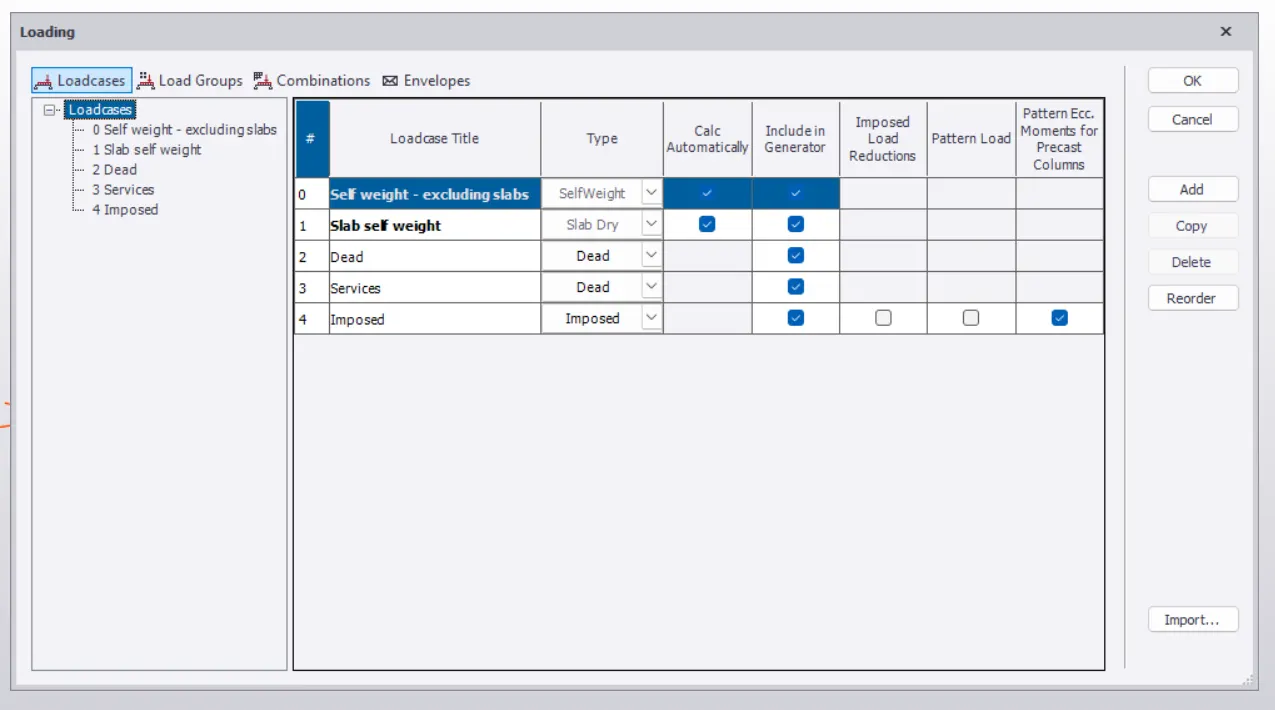
Click on laodcases in the load tab and check if there is dead load created, if not created then create load case named as dead load by
Clicking on Add option.
In the left bottom corner, select dead load in the load cases drop down.
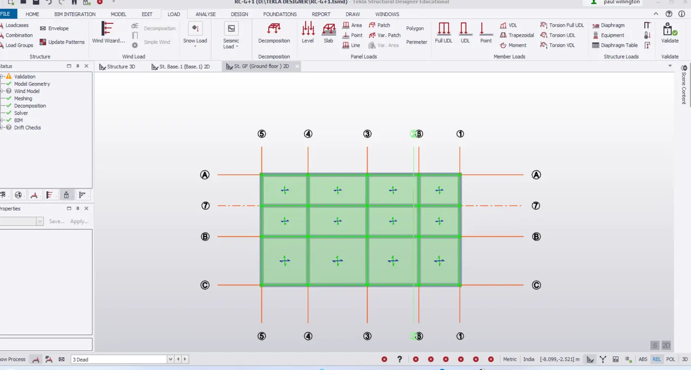
Click on area load in the load tab and enter the direction as Global z and value of load as 1.2KN/m^2. and select all the slabs for applying the
Slab loading.
Then click on the full UDL in laod tab and enter the value as 16.2Kn/m for ground floor and first floor and select the beam lines and extra walls
accroding to the plan.
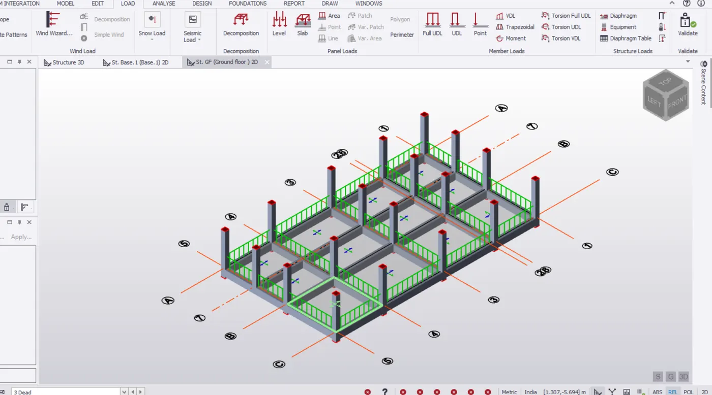
Again click on full UDL and enter the values as 1.5Kn / m for the roof floor walls.
RESULT-
The Model is loaded with Dead load as per IScode for the RCC structure.
- Calculate live load in design report based on IS code and apply dead load on the model
AIM- To calculate live load in design report based on IS code and apply it on model.
Tools Used- Load cases, Live load, Area Load, Property Window.
Calculations-
The live loads of different type of rooms is to be taken from IS 875 code part2.
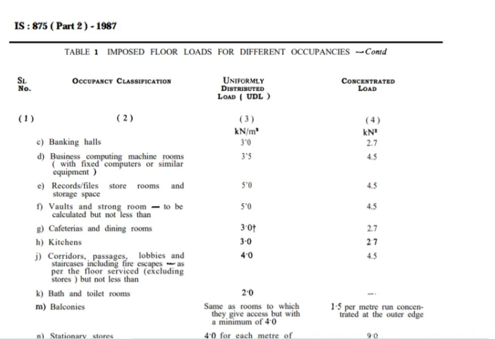
Procedure-
Click on load cases and create a load cases named as LIve Load and select the load type as Imposed in the type Dropdwon
and click Ok.
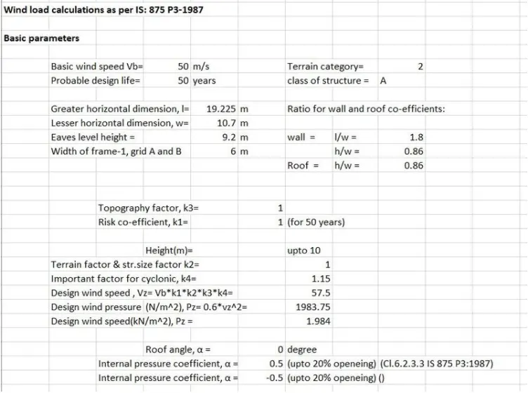
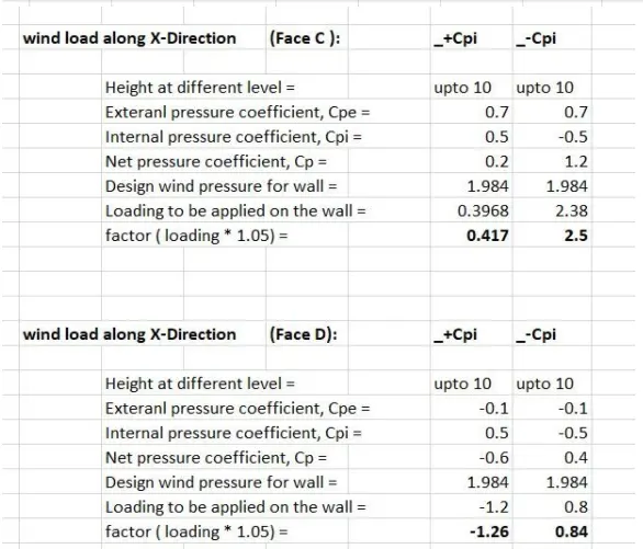
3.Generate manual wind loading in the design report based IS code as per the following input
- Basic wind speed = 50m/s
- Terrain category 2
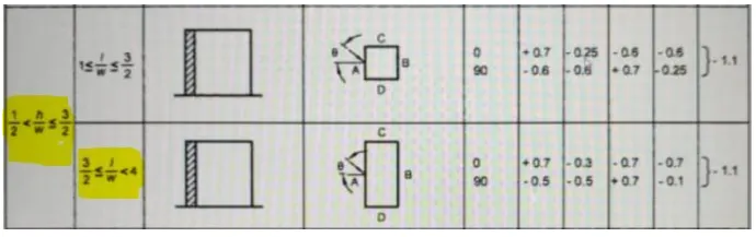
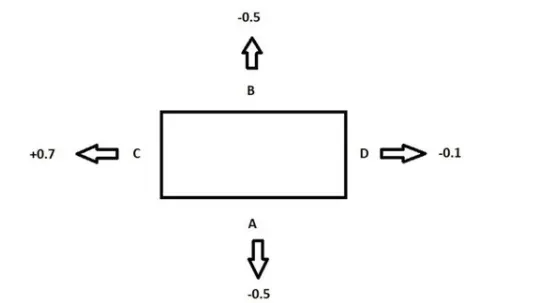
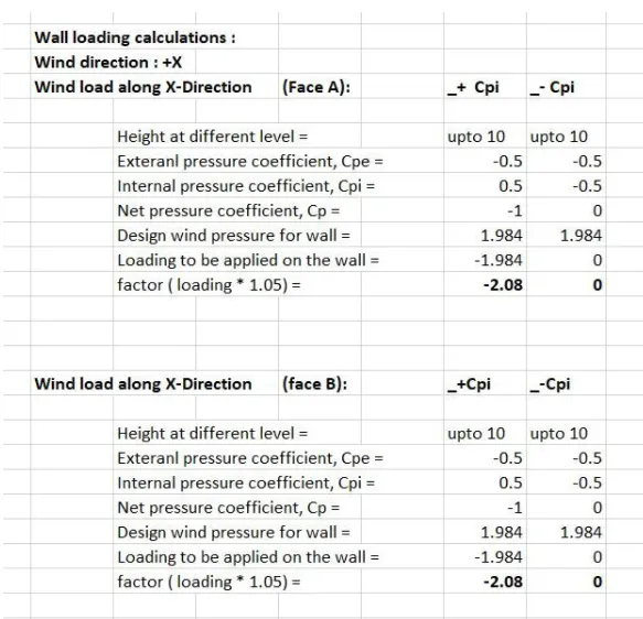
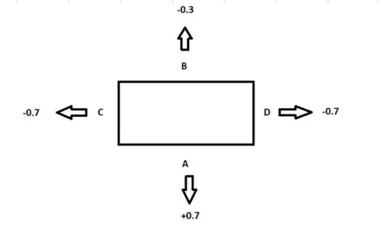
AIM- Generate manual wind loading in the design report based IS code with given input.
Calculation-
 \
\
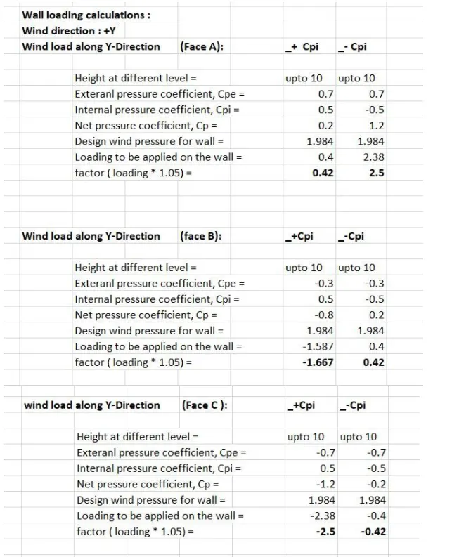
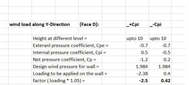
Caculations is performed successfully.
4. Based on the above calculation apply the loadings on the model
AIM- To apply the wind load calculation on the model.
PROCEDURE-
Click on Frames in the model tab and create frames for outer wall of the structure.
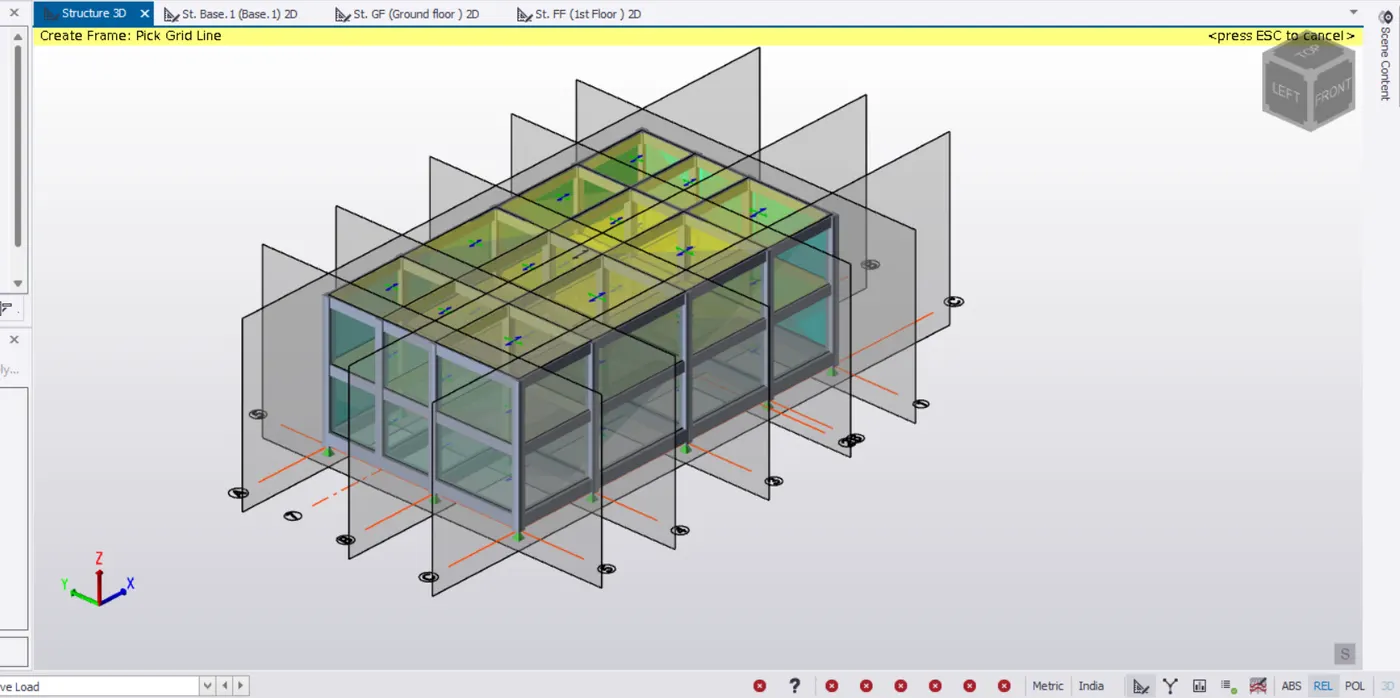
Open frame using the structure window and click on wall panels in the model tab and create wall panels in all frames.
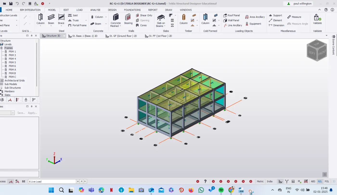
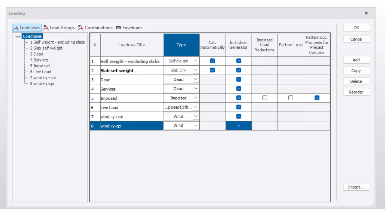
Now click on load cases in the load tab and add new load cases and them as wind load+Y+cpi, wind load+Y-cpi and select the type as wind load and click OK.
Open frame C which is considered as wall A and apply wind load +Y+cpi, Wind load +Y-cpi as per the calculation shown above
by clicking on area load and setting direction as Globaly Y and entering the value as 0.42 and 2.5 respectively.
Similarly repeat for frame A which is wall B and frame 5 which is wall C and frame 1 which is wall D.
Set Direction as Global X for walls C and D.
Result-
The wind loads applied on the wall of the structures and validate be error free.
Wind+Y+cpi
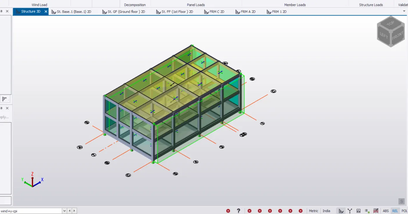
Wind+Y-cpi
Validate Structure.