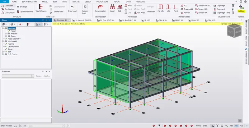
To calculate the dead , live and wind load for RC residential structure and to apply them using TSD
1.Aim:
To Calculate dead load in design report based on IS code and apply dead load on the model
Procedure:
- Open EXCEL to do the calculation.
- Enter the value as shown below.
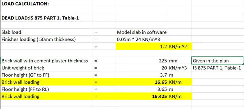
- Applying finishes:
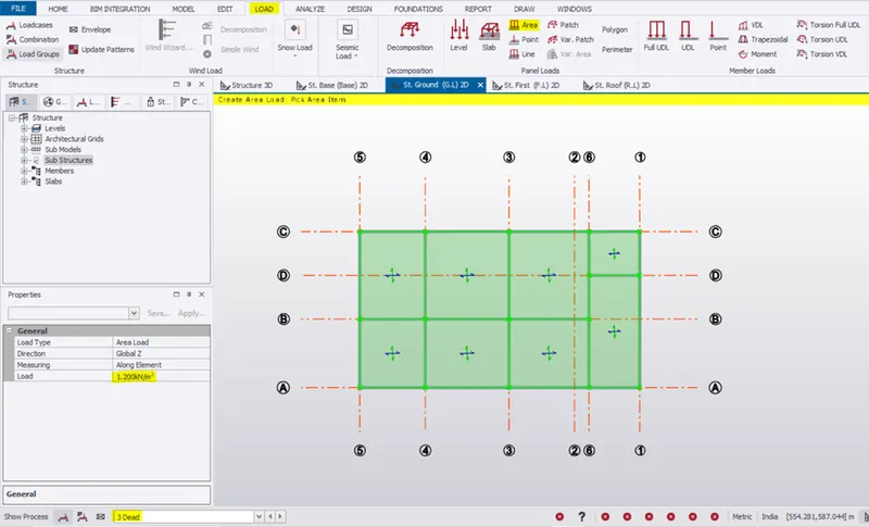
- Go to G.L and select the dead load from the drop down below and select load -> Area load
- Give the value and loading as shown below.
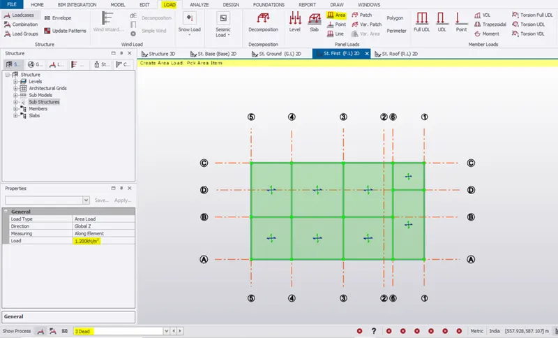
- Go to F.F and follow the same procedure.
- Go to R.L and give the loading.
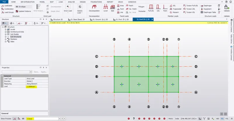
- Applying member load:
- Go to G.L and select load -> Full UDL
- Enter the value of load in the property window and click the member as shown below.

- Go to G.L and select load -> Full UDL
- Enter the value of load in the property window and click the member as shown below.
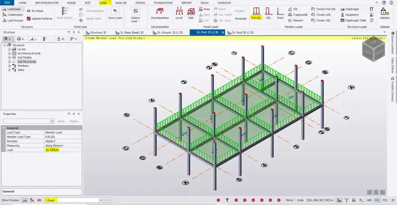
- Go to R.L and give the loading.
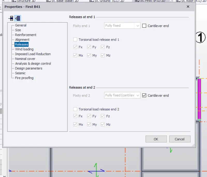
- Create cantilever beam:
- Go to FF and select concrete beam
- Draw a beam -> double to get property-> releases -> select beam end as cantilever.
- Copy the corner beams and connect the beams as shown below.
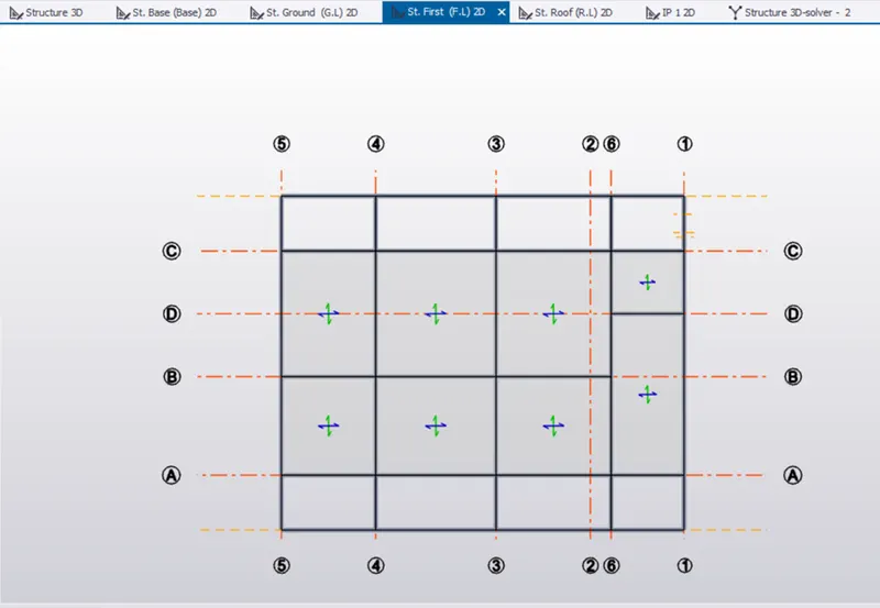
- Create slab by slab on beam icon and click inside the beam area
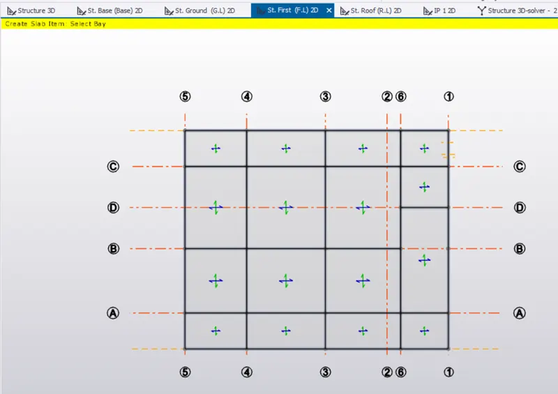
- Apply dead load as mentioned earlier.
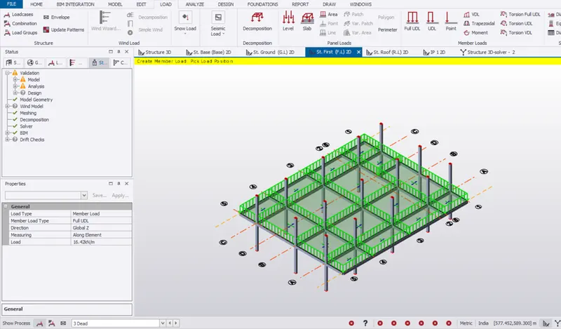
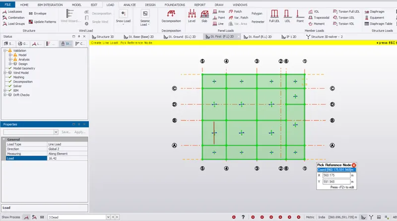
- Go to F.F, load -> line load
Results:
Hence the dead load is applied
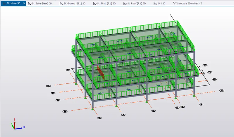
2.Aim:
To Calculate live load in design report based on IS code and apply live load on the model
Procedure:
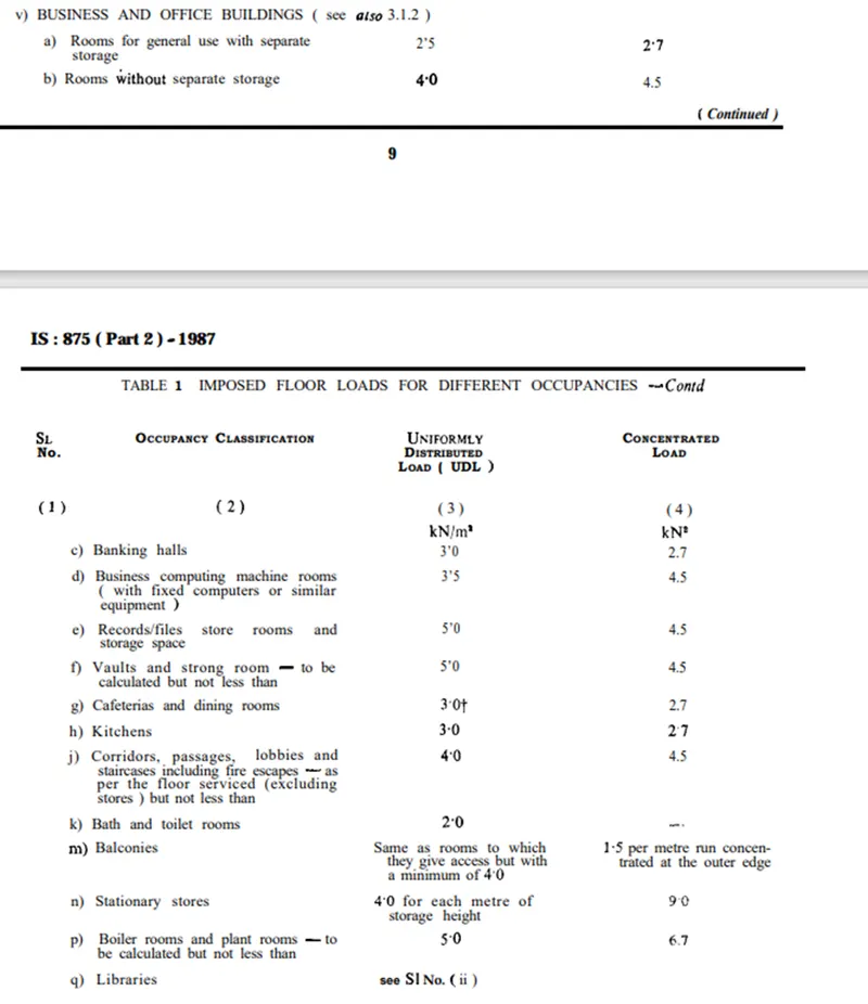
- Refer IS 875 Part -2, Table- 1 for Live load
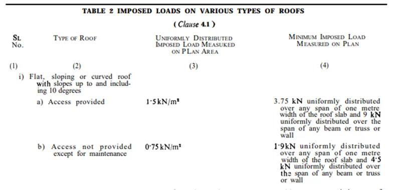
- For roof,
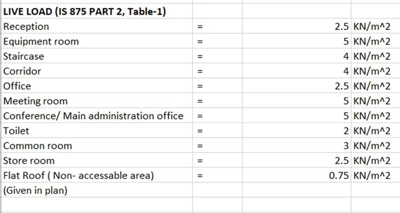
- Open EXCEL and enter the values.
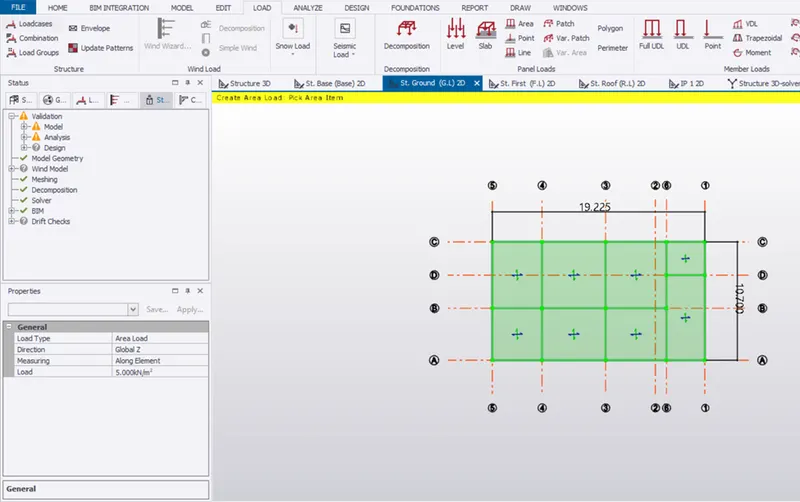
- Go to G.F and select load-> area load and give loading as per the calculation
- Go to F.F and select load-> area load and give loading as per the calculation
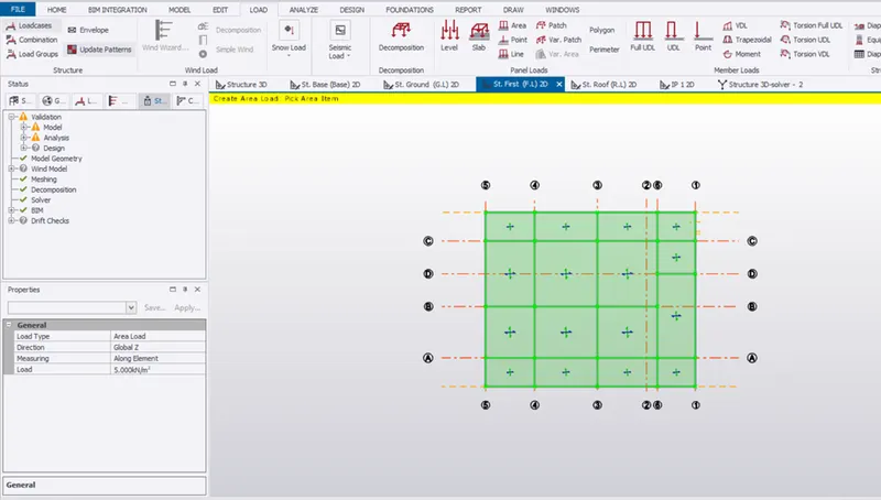
- On roof
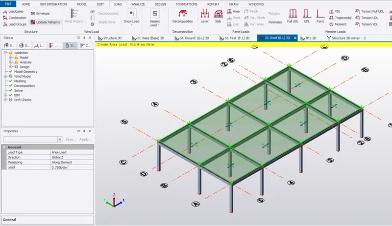
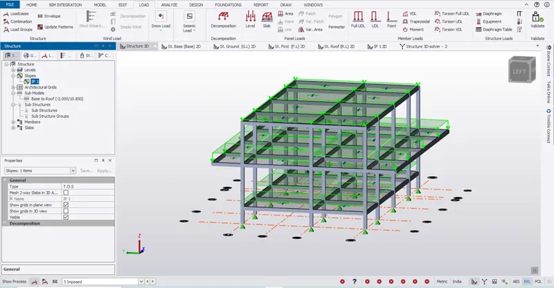
- Results:
- Hence the live load is applied on every level
3.Aim:
To generate manual wind loading in the design report based IS code as per the following input
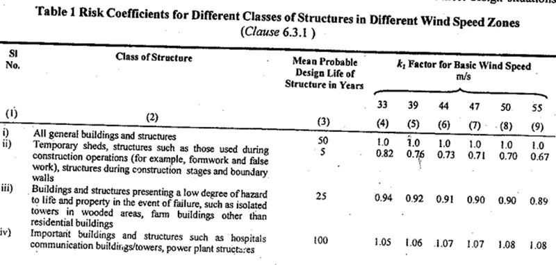
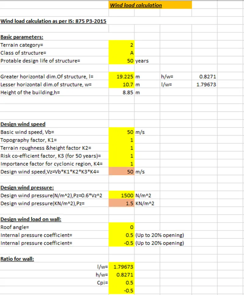
- Basic wind speed = 50m/s
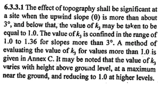
- Terrain category 2
Procedure:
- Open Excel sheet for calculation and open TSD file which created early to check dimension of the building.
- Refer code IS 875 Part-3 2015 for,
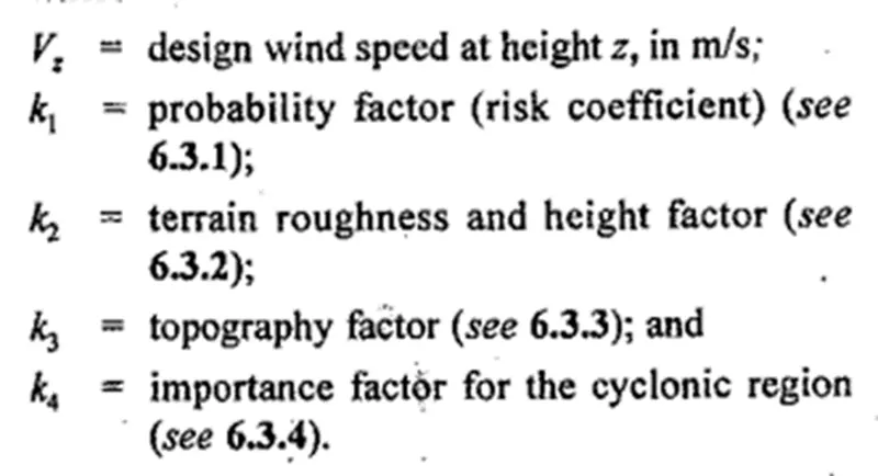
- For K1,
- K2 factor is,
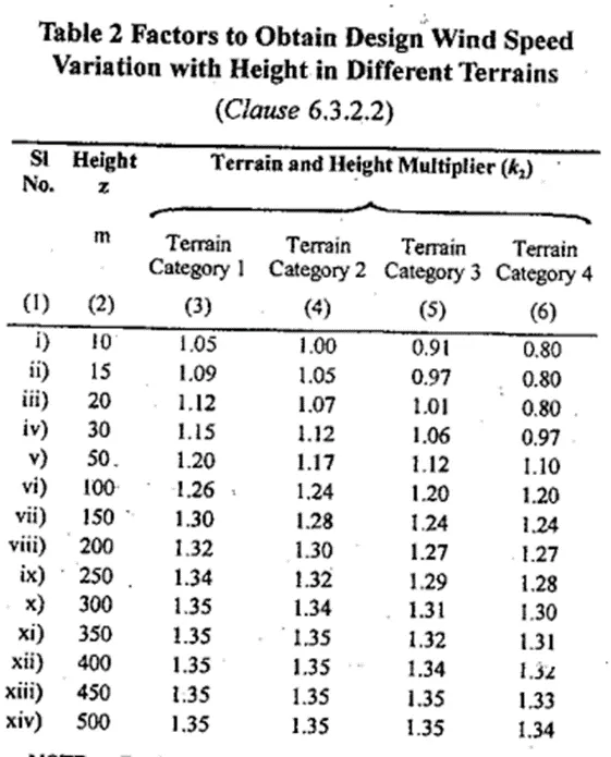
- For k3,
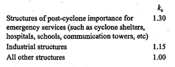
- For k4,
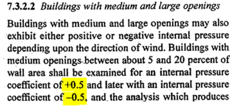
- Internal pressure coefficient- 7.3.2.2
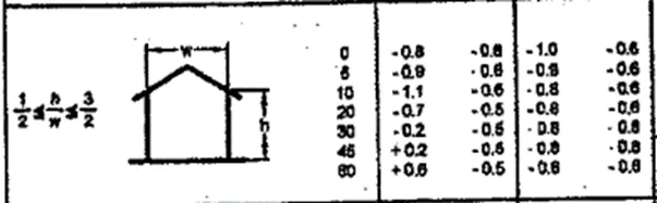
- For external co-efficient, Refer Table 5

- With the above reference, Enter the value in excel for calculation.

- Roof:
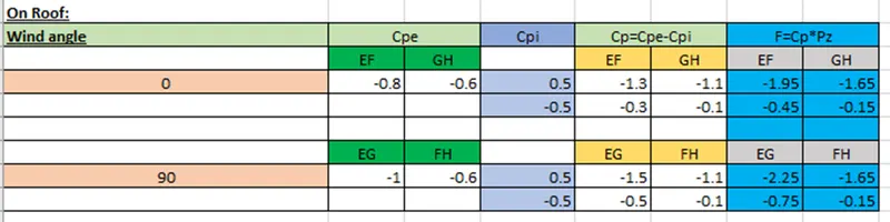
- Result:
- Hence, the calculation is done by referring IS 875-2015 Part-3.
4.Aim:
To apply the loadings on the model by the above calculation.
Procedure:
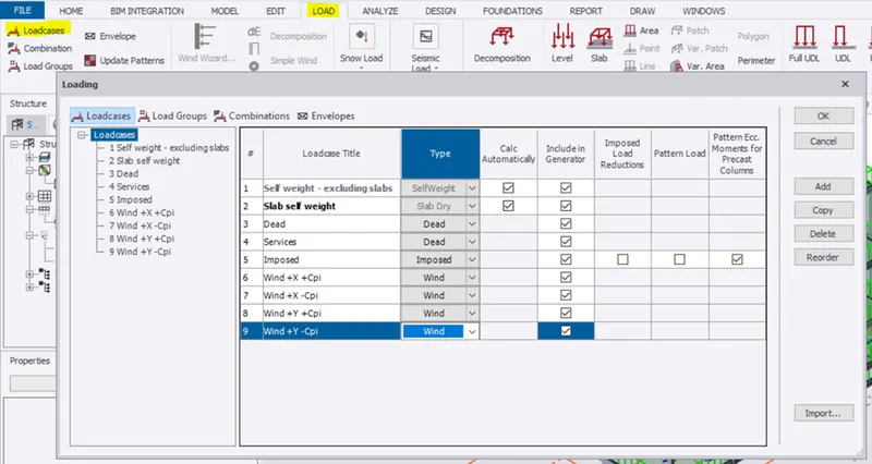
- Creating load case:
- Go to load -> Load cases-> add
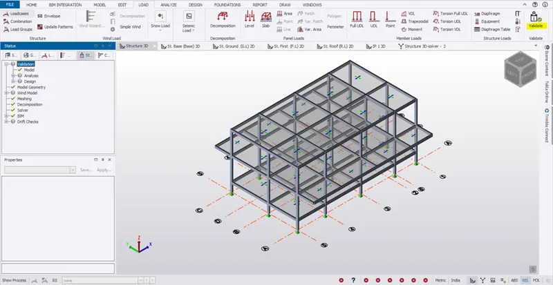
- Validate the model:
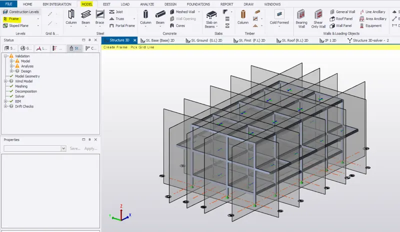
- Creating frames:
- Go to model -> Frames
- Select grids
- Creating wind panel:
- Go to FRM A 2D -> model -> wall panel -> pick corners of the columns
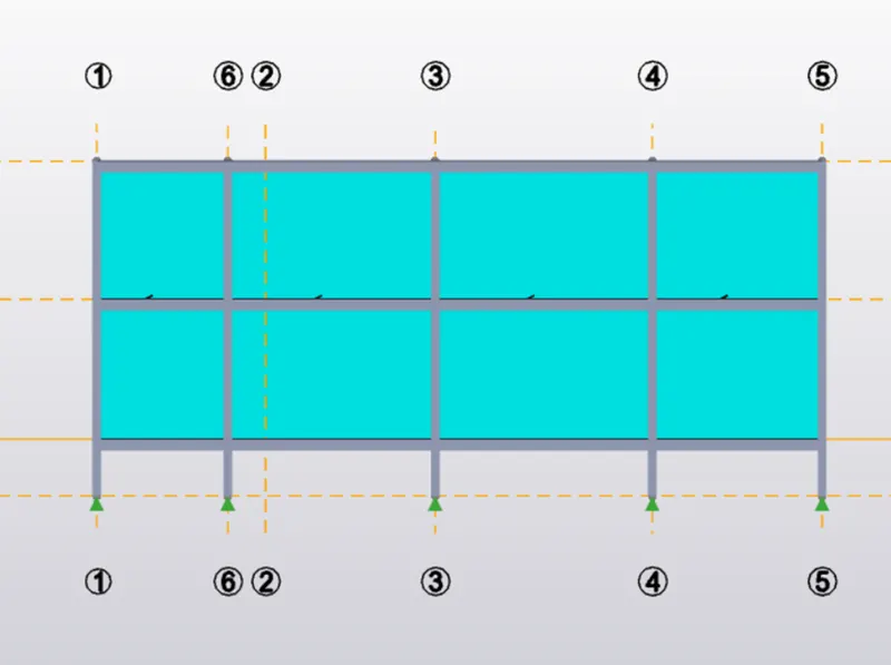
- Similar create it on all 4 sides
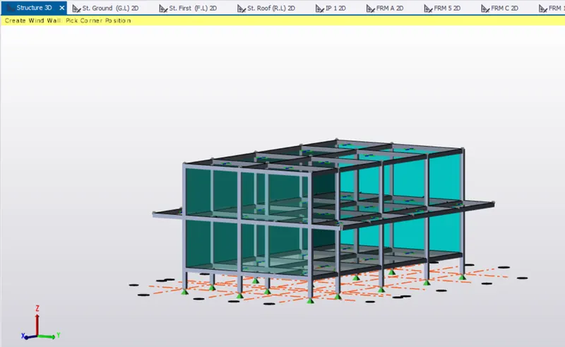
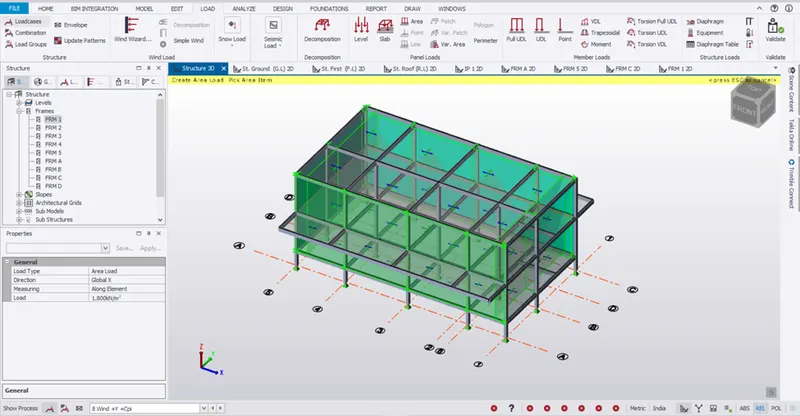
- Applying wind load: Wind +X +Cpi
- Select the load case -> load -> area load and enter the loading on the property window by referring the wind load calculation and select the wall panel on wind ward side
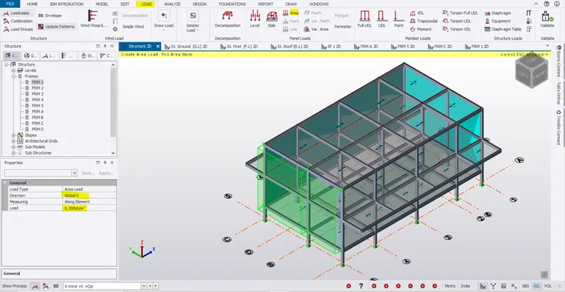
- Follow the same procedure on wee ward side
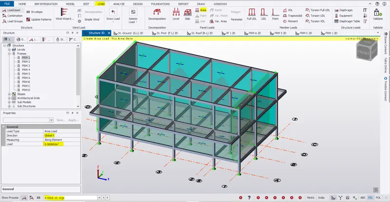
- Follow the same procedure on face C
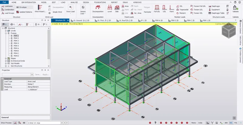
- Follow the same procedure on face D
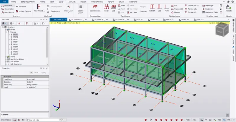
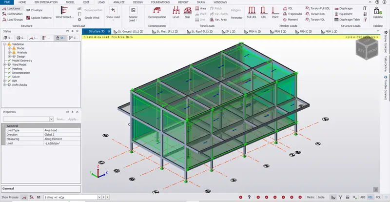
- On roof:
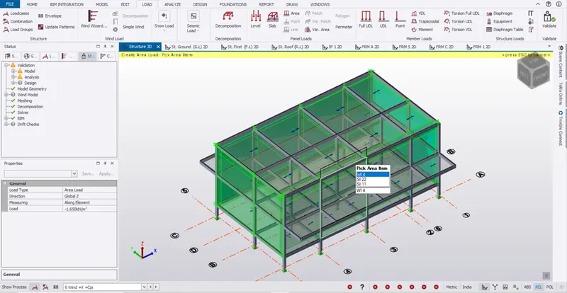
- Follow the same procedure but change the load case to Wind +X -Cpi
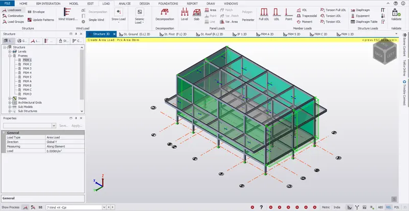
- On roof:
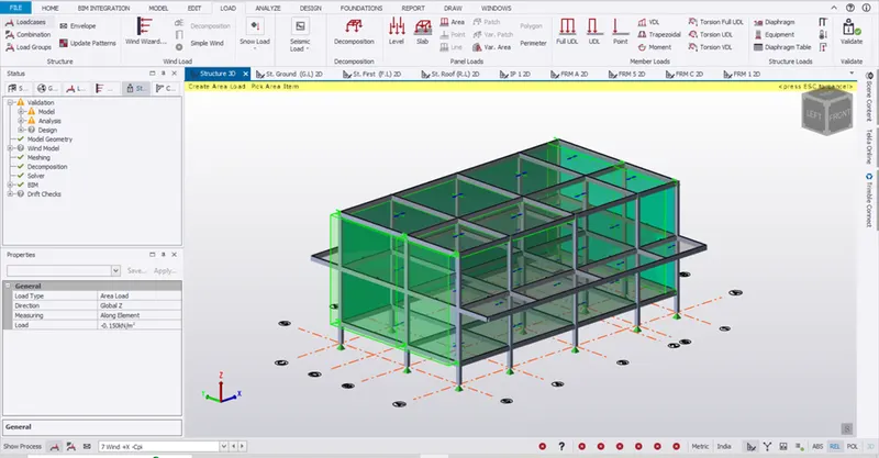
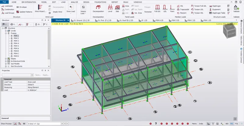
- Similarly for Wind +Y +Cpi
- On roof
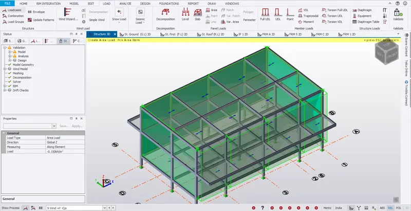
- Similarly for Wind +Y -Cpi
- On roof:
- Result:
- Hence the loads are applied as per the above calculation.
- Validate the model