To calculate dead and live load for industrial steel structures and to apply them using TSD
- Calculate dead load in design report based on IS code and apply dead load on the model
- Finishes of 50mm
- Slab as per design
- Brickwall 150mm thickness
- Roofing load based on purlin size
- Ceiling loading 0f 0.3KN per sq m
AIM:- To calculate dead load in design report based on IS code and apply dead load on the model:-
- Finishes of 50mm
- Slab as per design
- Brickwall 150mm thickness
- Roofing load based on purlin size
- Ceiling loading 0f 0.3KN per sq m
INTRODUCTION:- Dead load are normally the weight of th structural member which includes the weight of the slab, beam, column, roof,etc that are permanently available in the structure.
PROCEDURE:-
- Open the TEKLA STRUCTURAL DESIGN software in which the previous modelling is done.
- Open a NEW file in MS EXCEL for calculation of dead load and live load.
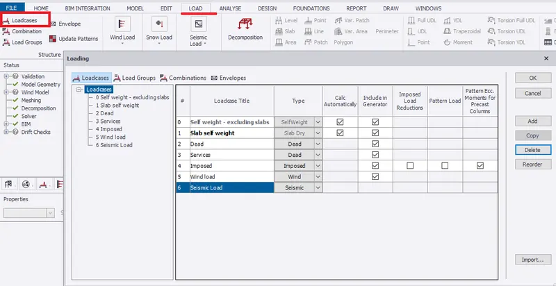
- Go to LOAD tab, select LOADCASES from ribbon tab.
- A LOADING window appears on the screen.
- Under loadcase, we need to define self weight with and without slab load, dead load, live load, seismic load and wind load. Click on ADD to dead load after self weight, similarly add on live load,etc. Click on OK.
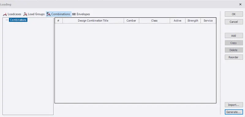
- Select load combinations in loading window. Select GENERATE.
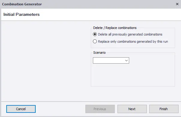
- To set inital parameters under combination generator opt for DELATE ALL PERVIOUSLY GENERATED COMBINATIONS. Click on NEXT.
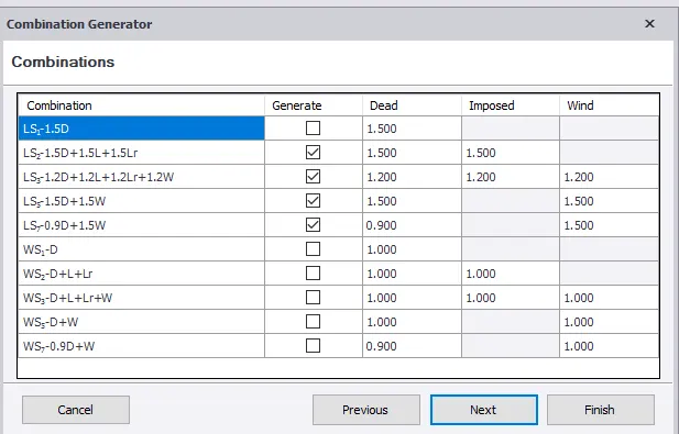
- A list of load combinations appears on the window as shown below. Click on NEXT.
- Next, a list of service load appears as shown. Click on NEXT.

- Combinations are generated. Click on FINISH.
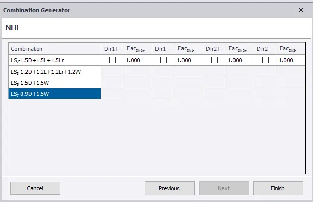
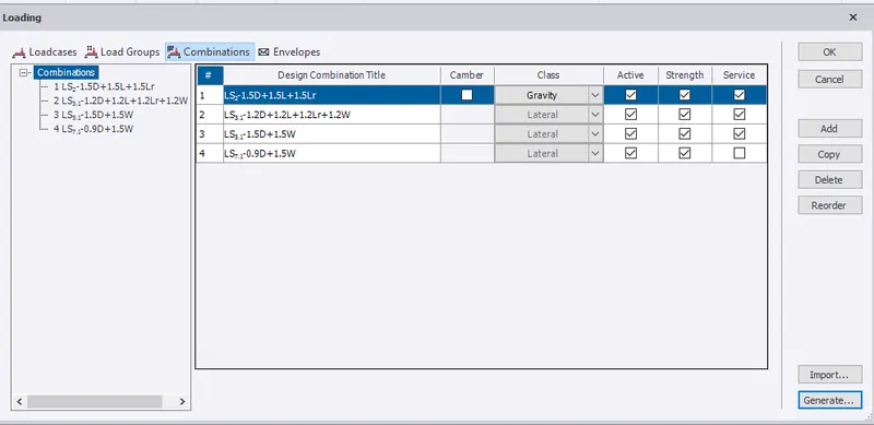
- Load combination are generated. Click on ok.
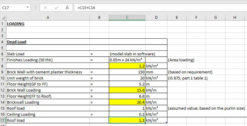
- Data for dead load is calculated and inputed in MS EXCEL as shown below.
- Dead load of the slab is automatically designed by software and applyied to the beam.
- Given, floor finish of 50mm thick which is provided of both ground floor and first floor. Therefore, finish load = thickness of floor finish x density of concrete. ie, 0.05mx 24kN)m3=1.2kNm2��)�3=1.2���2
- Given, Brickwall thickness is 150mm.
- In IS 875(part 1, Table 1), unit weight of brick is shown below, which ranges around 15.7 to 24.5 kN/m^2. Therefore, overhere unit weight of brick is taken as 20 kN/m^2.
- Therefore, brickwall loading= unit weight of brick x brickwall thickness x floor height.
- For eg, brick loading for ground floor= 20 x 0.15 x 5.2= 15.6 kN/m.
- Similarly, for first floor brick loading= 20x0.15x6.8= 20.4kN/m.
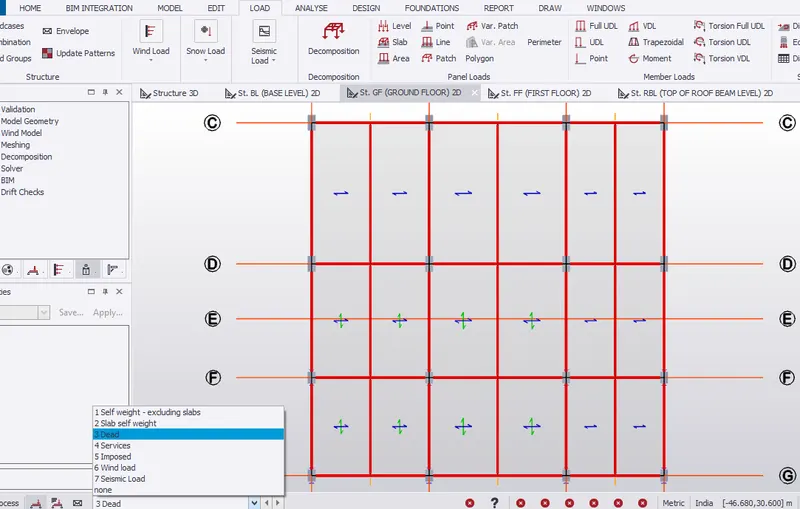
- In ground floor, select DEAD LOAD from loadcase.
- Under LOAD tab, select AREA load from ribbon tab.
- In property window, provide loading intensity of 1.2kN/m^2 for floor finish.
- Pick each area where area loading has to be provided.
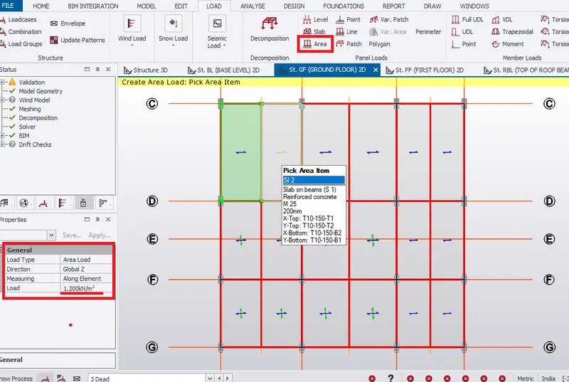
- Finally, floor finish load is applied on ground floor.
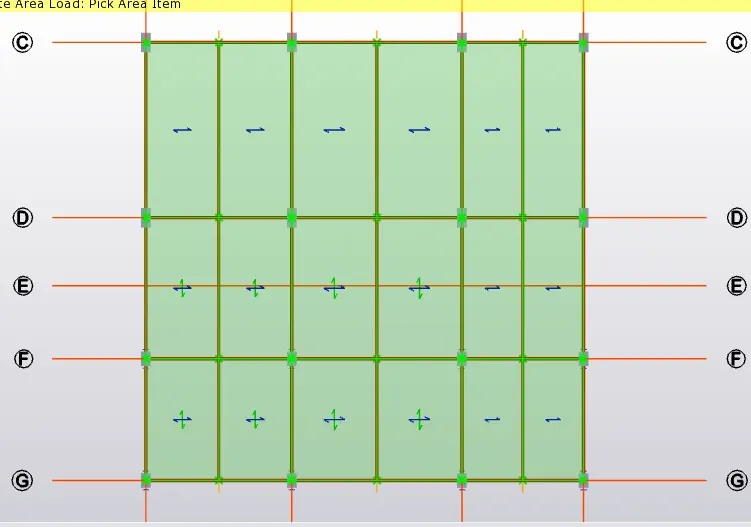
- Validate the model. Hence, no error.
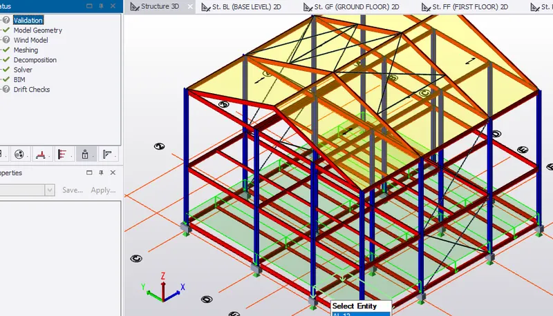
- Check the dead load (floor finish) in 3D view.
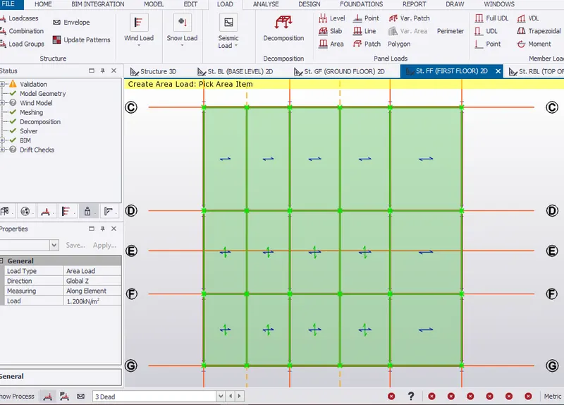
- Similarly, go to first floor to apply the floor finish load by selecting dead load in the loadcase.
- Select AREA LOAD in ribbon tab. Specify load intensity of 1.2kN/m^2 .
- Pick the area to apply floor finish.
- Similarly, apply the floor finish load in top of beam level by selecting dead load in the loadcase.
- Select AREA LOAD in ribbon tab. Specify load intensity of 1.2kN/m^2 .
- Pick the area to apply floor finish.
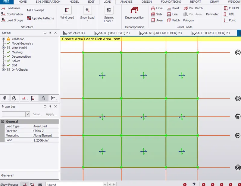
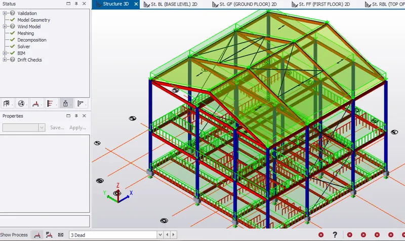
- Validate the model in 3D view and also, check the floor finishes applied.
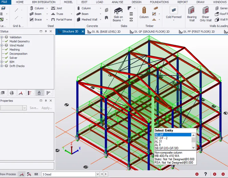
- To apply full brick wall load on outer wall of the ground floor.
- Select FULL UDL in ribbon window. Load type is Member load. Change load intensity to 15.6kN/m
- Pick the member to create loading position.

- 3D view of the outer brickwall is shown below.
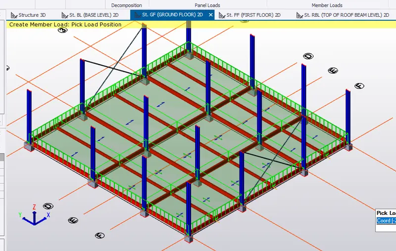
- Staircase brickwall is applied at 3m from grid line 1. So, pick a full UDL at an intensity of 15.6kN/m.
- Similarly, refer ground floor plan to apply brickwall load grid line 1 and 2 and also between C and D as shown below.
- Apply line load from loadcase and specify load intensity of 15.6kN/m.
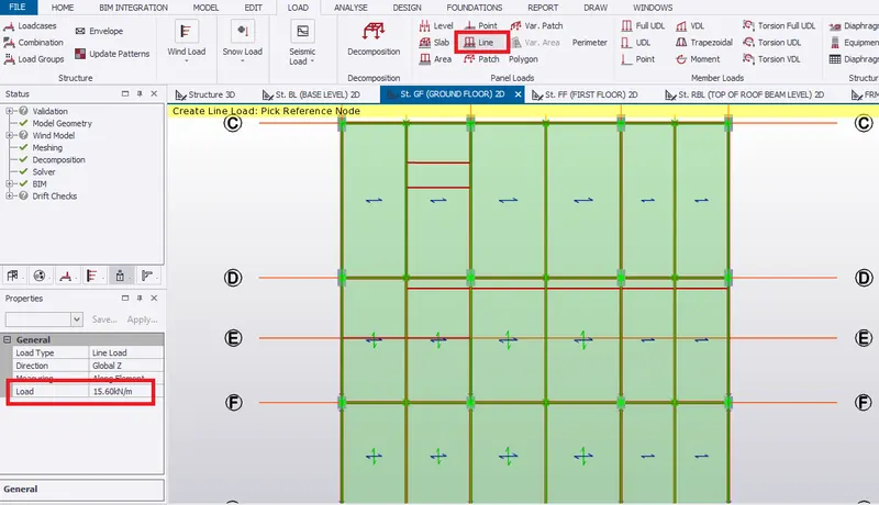
- On validating, no error found.
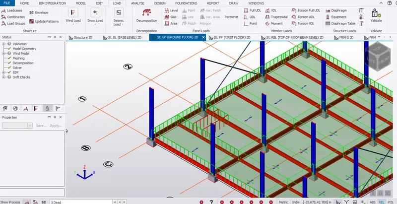
- Similarly, refer ground floor plan to apply brickwall load as per requirement and lastly validate to check any error in loading.
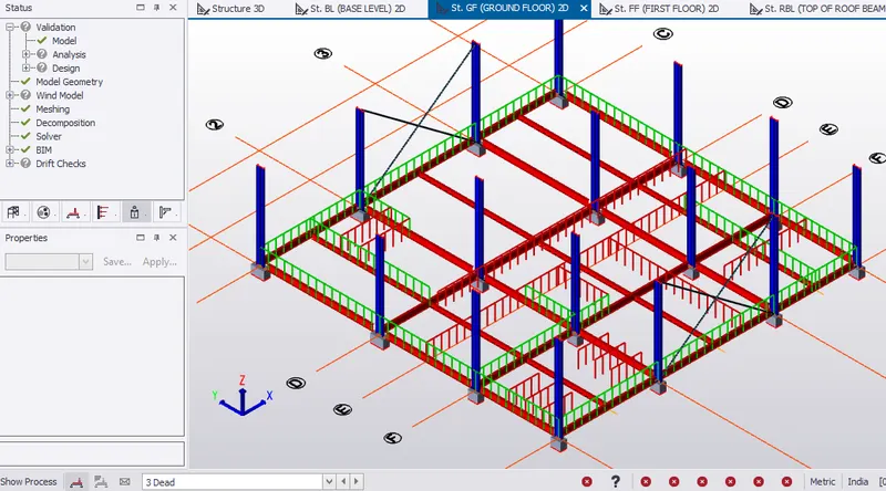
- Similarly, go to the first floor to create brickwall load on the outer and inner wall.
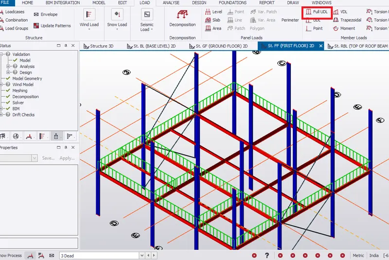
- In the first floor, apply the full lenth UDL(ie, load type- member load) of 20.4kN/m at position shown below.
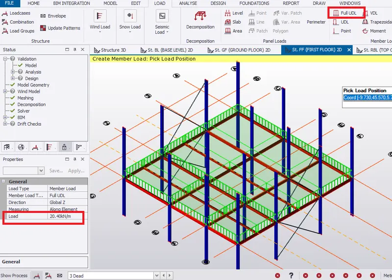
- Also, apply brickwall load for staircase of 20.4kN/m
- Next, apply line load for brick wall which is away from member by selecting line load from loading ribbon tab.
- Set line load of 20.4kN/m for brickwall load.
- For example, to create brickwall load for meeting room, select line load , pick the reference point and specify the distance from reference (ie, start point and end point) which mention the brickwall length.[MARKED IN RED]
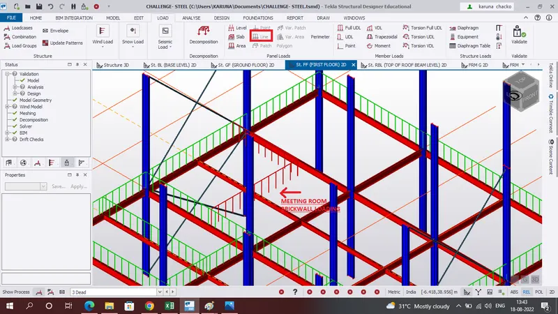
- Similarly, create brick wall load(ie, picking line load) at different load.
- Brickwall load between grid line C and D is created.
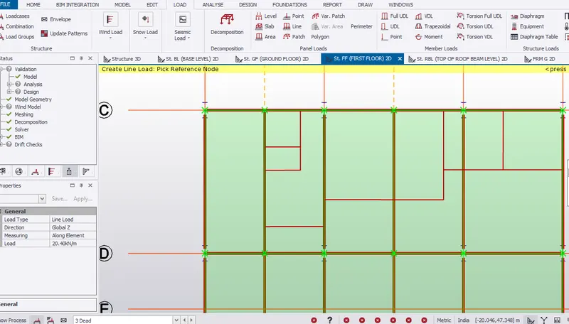
- Similarly, brick wall load at various locations are created.
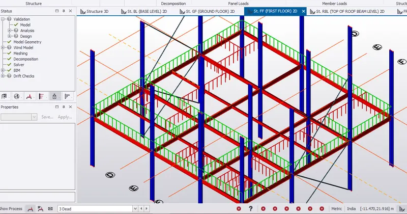
- Finally, brick wall load in the first wall is created as plan drawing and no error found on validation .
Roof loading
- Go to 3D scene view.
- Turn off the slab items, wall panel from the scene content for better view of roof load.
- Change loadcase to DEAD. Go to loading tab, select area load in ribbon tab.
- Change load intensity to 1.3 kN/m^2 (ie, total roof load =ceiling load+ purlin load =0.3+1= 1.3 kN/m^2
- Given, ceiling load= 0.3 kN/m^2
- To create roof load, pick the roof panel.
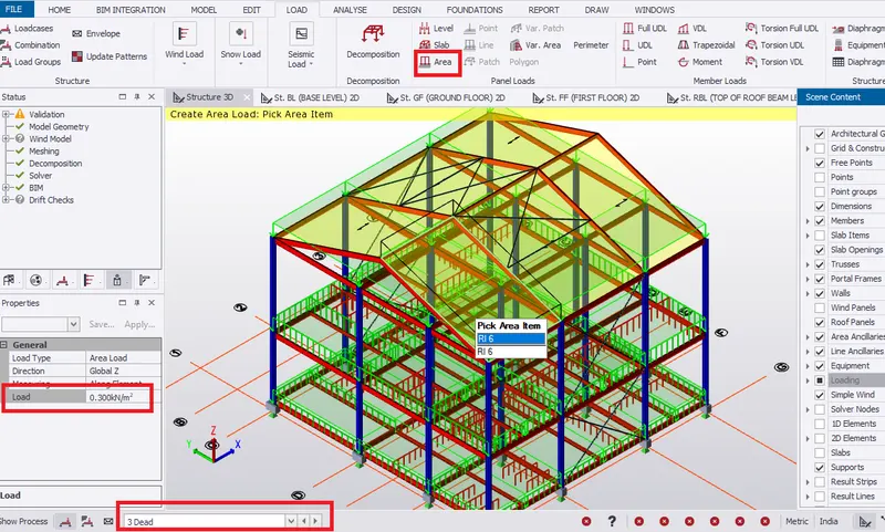
- Simentanously, pick rest of the roof panel
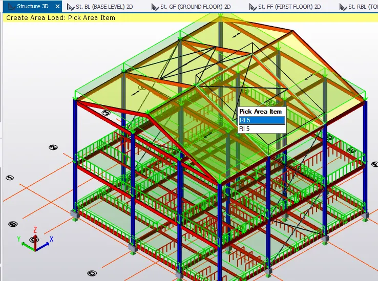
RESULT:- Hence, dead load is calculated as per IS 875 part 1 and applied to the model as shown below.
- Calculate live load in design report based on IS code and apply live load on the model
- Assume the loading based on IS 875
- Roof loading
- Consider equipment loading as 5KN per sq m
AIM:- To calculate live load in design report based on IS code and apply live load on the model
- Assume the loading based on IS 875
- Roof loading
- Consider equipment loading as 5KN per sq m
INTRODUCTION:- Live load are usually due to the weight of the occupant or weight of anything that is moving or varing. Code refered for live load is IS 875, part 2,1987 ,table 1 for industrial building. Also, refer Table 2 for live load on roof.
PROCEDURE:-
- Firstly, study the floor plan, Its room arrangements, etc
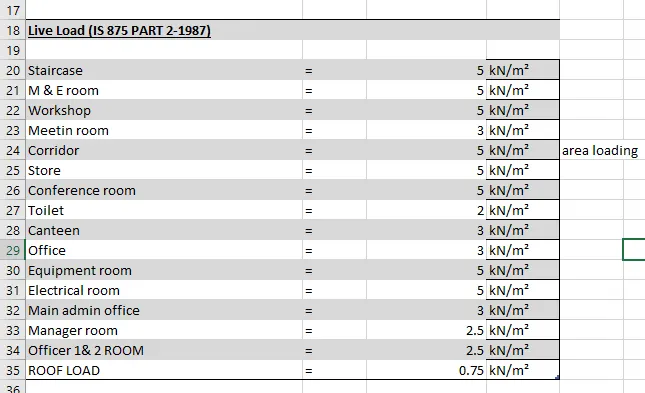
- Next, input the Live Load values of each room requirement in MS Excel as per requirement as refered from IS 875, part 2,1987.
- Given, equipment load = 5kN/m^2
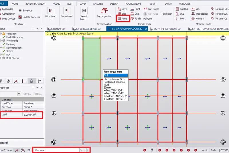
- Let's consider ground floor in the software, change the loadcase to IMPOSED.
- Select to AREA load in ribbon tab under LOAD tab.
- Change the load intensity to 5kN/m^2 for staircase as mentioned in the table above.
- Pick the area where area load is to be created.
- Continue with same loading in workshop area as well.
- Since the office area has a live load of 3 kN/m^2 ,we will provide 5kN/m^2 due to existance corridor in that particular area.
- Since the toilet area has a live load 2kN/m^2, we will change load intensity to 2kN/m^2 in property window
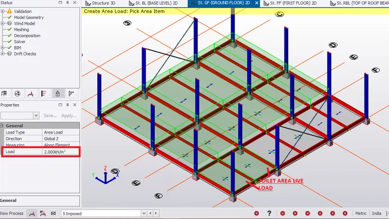
- Similarly, change load to 3kN/m^2 for canteen and offce area.
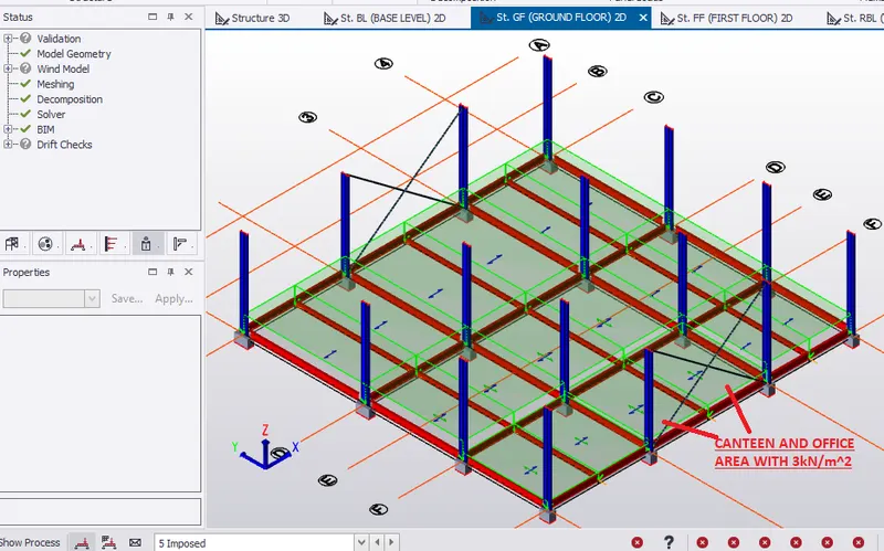
- Similarly, continue doing in the first floor as well.
- Change to imposed load in the loading panel.
- Create the area loading with loading intensity of 5kN/m^2 in property window.
- Pick the area to create area load.
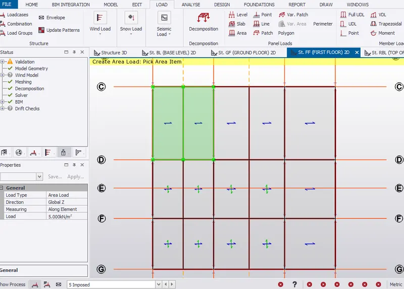
- Similarly, specify live load area for different slab area with load shown in the table above. We can see the level difference in the loading.
- Validate the model to check any error in the loading.
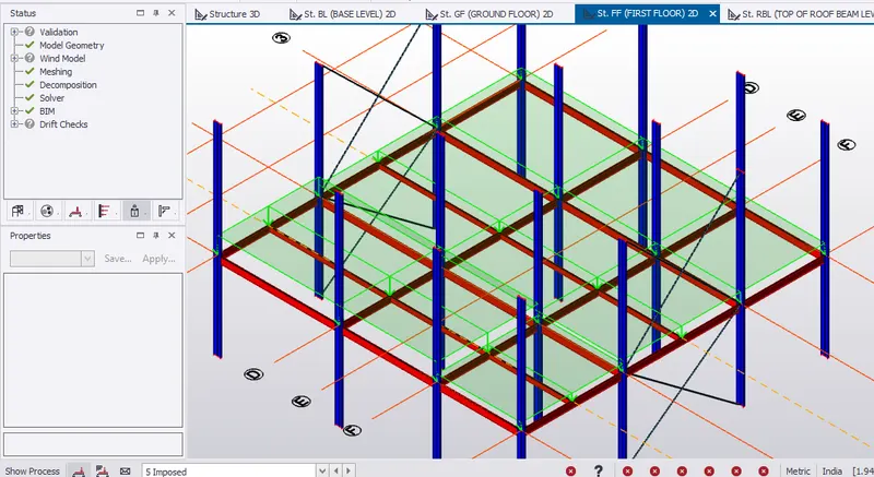
Live load on Roof
- Go to 3D view in scene view.
- Change to IMPOSED load in loading panel.
- Select area load in loading tab.
- Change load intensity to 0.75kN/m^2 in property window as per IS 875 part2 Table 2.
- Pick the roof panel to apply live load.
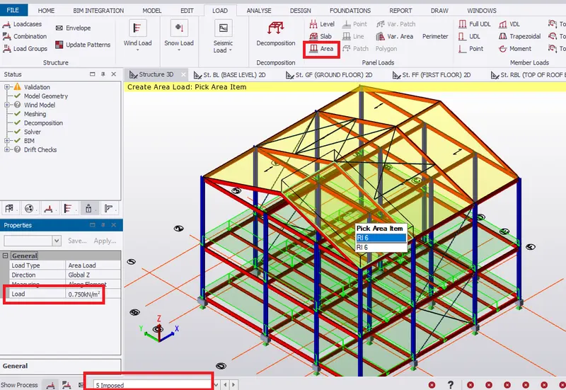
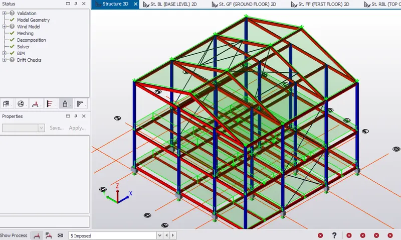
RESULT:- Hence, Live load is calculated as per IS 875 part 2 and applied to the model as shown below.
- Generate a calculation for 5T crane loading based on following inputs
- Centre to Centre of wheel = 10m
- Weight of crab = 40 KN
- Number of wheels = 4
- Wheel base = 2m
AIM:- To generate a calculation for 5T crane loading based on following inputs:-
- Centre to Centre of wheel = 10m
- Weight of crab = 40 KN
- Number of wheels = 4
- Wheel base = 2m
INTRODUCTION:- Cranes are mainly used in Industrial building to lift heavy objects in the workspace for maintaince and fabrication works. Crane frame are provided between two columns.
PROCEDURE:-
- To generate calculations for crane loading.
- The given values
- Centre to Centre of wheel = 10m
- Weight of crab = 40 KN
- Number of wheels = 4
- Wheel base = 2m
- Consider
- Crane capacity = 50 kN
- Number of wheels on each side = 2
- Weight of the crane = 60 kN
- c/c distance between two column = 5.5 m
- Max. wheel load
- Max concentrated load on the crane = crane capacity+ weight of crab = 50+40 = 90kN
- Self weight of crane will act as UDL= 60/10 =6kN/m
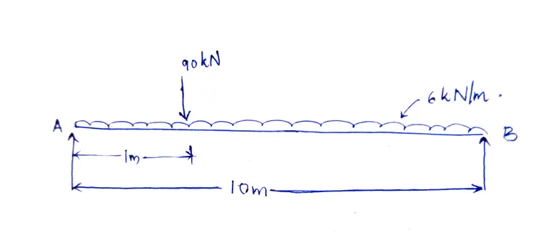
- Taking Moment about B
- (6x10x5)+(90x9)=RA x 10 ; RA = 111kN
- RB =39 kN
- Reaction from crane girder is disturbed equally on 2 wheels at the end of crane girder
- Maximum wheel load on each wheel =RA/2 = 111/2= 55.5kN
- Maximum Bending Moment
Assume self weight of gantry girder = 1.5 kN/m
Assume self weight of rail = 0.3 kN/m
Total dead load = self weight of gantry girder + self weight of rail =1.5+0.3 =1.8kN/m
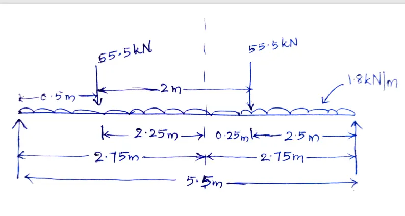
Taking moment at D
Rc x 5.5= (55.5 x 5)+ (55.5 x 2.5)
Rc=75.68 kN
Taking moment at C
RD x 5.5 =(55.5 x 3)+ (55.5 x 0.5)
RD= 35.32 kN
Bending Moment (BM) under wheel due to Live Load = 2x RD =2 x 35.32 = 70.64 kNm
BM due to impact= 10% increase due to MOT = 0.1 x70.64= 7.064 kNm
BM due to Live Load and impact =70.64 +7.064 = 77.7 kNm
BM due to Dead load = wl2/8 = (1.8 x5.5 x5.5)/8 = 6.81 kNm
Maximum BM = 77.7+ 6.81 = 84.5 kNm
- Maximum Shear Force
For max. shear force, one of the wheel should be at the support
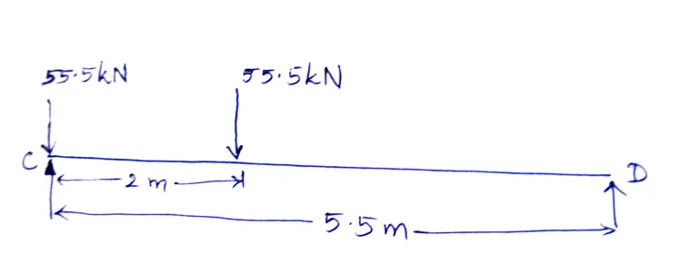
At D, Rc x 5.5 = (55.5 x 5.5) + (55.5 x3.5)
Rc = 90.8 kN
Max. shear force due to wheel load= 90.8 kN
- Lateral Force
Lateral force transverse to rail = 5% of weight of crab and weight lifted
= 0.05 x( 40+50) = 4.5kN
Lateral force on each wheel = 4.5/2= 2.25 kN
Horizontal reaction due to lateral force by proportion at C
= lateral force x reaction at C due to vertical load/ maximum wheel load due to vertical load
=2.25 x 75.68/55.5 = 3.068 kN
At D, load= 4.5- 3.068= 1.432 kN
Bending Moment due to lateral force by proportion at C =2.25x 90.8/55.5= 3.68 kNm
RESULT:- Hence, generated a calculation for 5T crane load with given values.