To calculate dead and live load for industrial steel structures and to apply them using TSD
1.Aim:
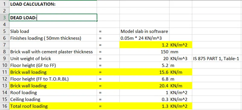
To Calculate dead load in design report based on IS code and apply dead load on the model.
Given data:
- Finishes of 50mm
- Slab as per design
- Brick wall 150mm thickness
- Roofing load based on purlin size
- Ceiling loading 0f 0.3KN per sq m
Procedure:
- Open the TSD file which is been modelled for the last challenge.
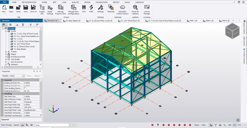
To model slab:
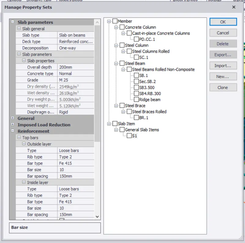
- Go to Home -> Manage property sets-> New -> General slab items
- Rename it as S1 and give the following property for One- way slab
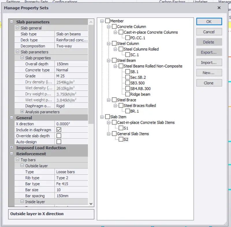
- Go to Home -> Manage property sets-> New -> General slab items
- Rename it as S2 and give the following property for Two - way slab
- Take the dimensions to choose the slab types from the above creation.
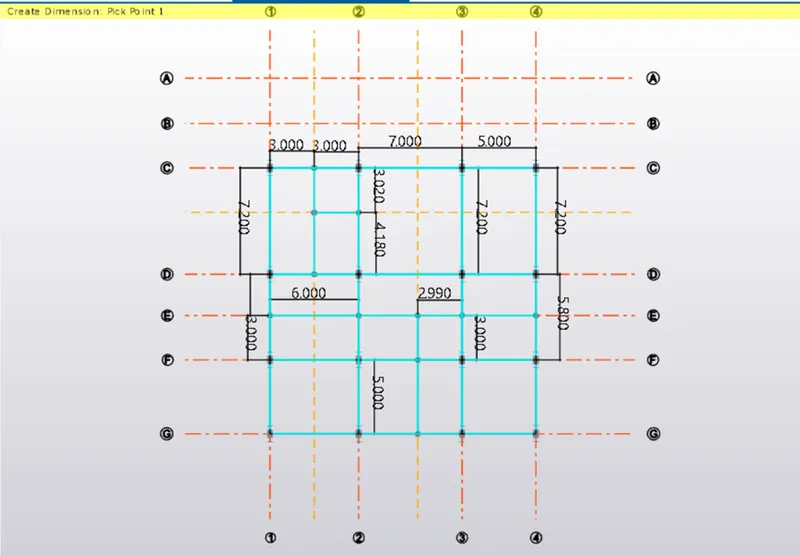
Modeling slab:
- Go to G.L and select Model -> Slabs on beams and select Slab on beams and appropriate slab property in the property window.
- Click inside the grid where it’s needed.
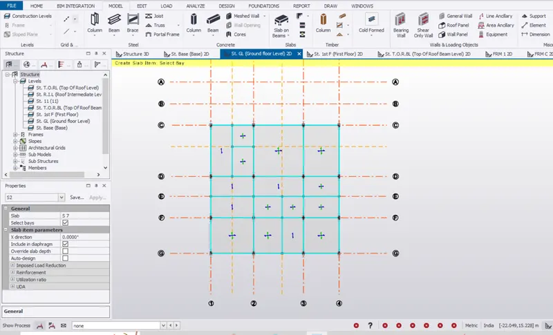
- Follow the same procedure for first floor level but keep the stair area free.

- Go to Top of Roof Beam Level and follow the above procedure.
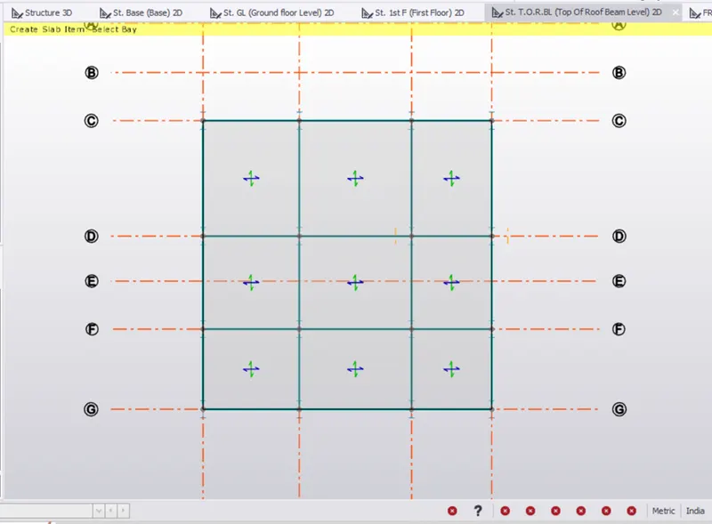
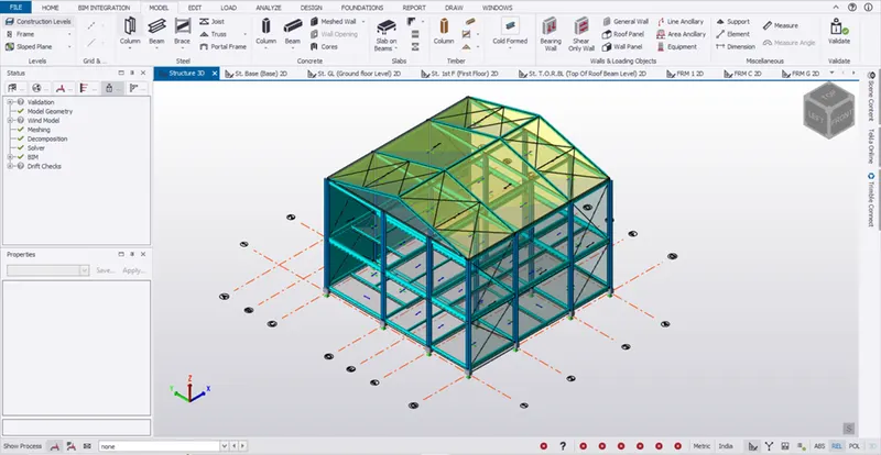
- Go to 3D view to view as a whole.
- Validate the model.
- Go to Load -> Load cases and add the following loads as required by clicking add button in the loading dialog box.
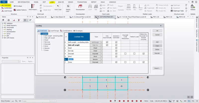
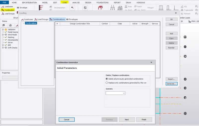
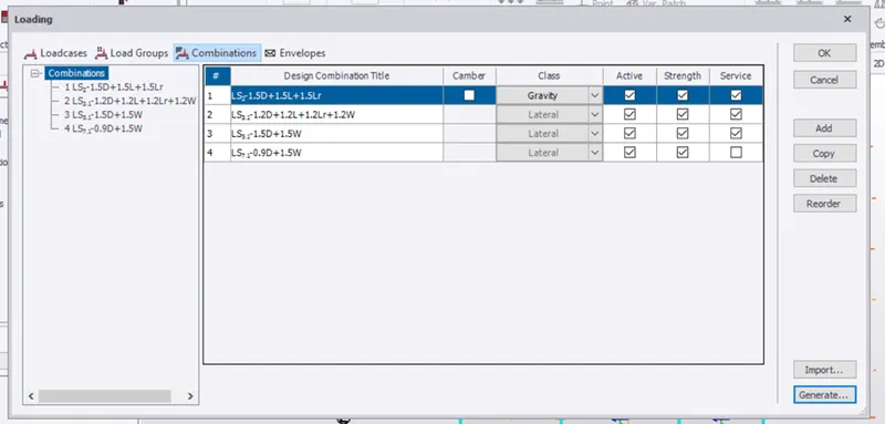
- Go to Load -> Load combination - > Generate and select the following option.
- Open MS Excel and do the load calculation for Dead load as shown below.
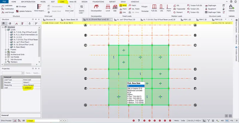
- In TSD, Go to Ground level select load as Dead in the drop down below.
- Go to Load -> Area load, enter value as 1.2 KN/m2 in the property.
- Click on each slab
- Validate the model and proceed.
- Go to First floor level and follow the same procedure.

- Go to Top of Roof Beam Level and follow the same procedure.
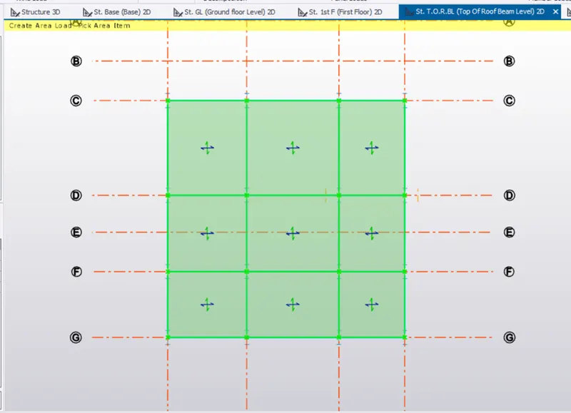
- Go to 3D view to check and validate.
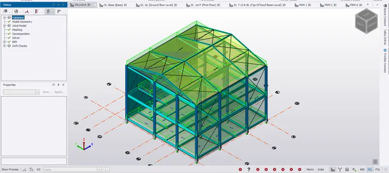
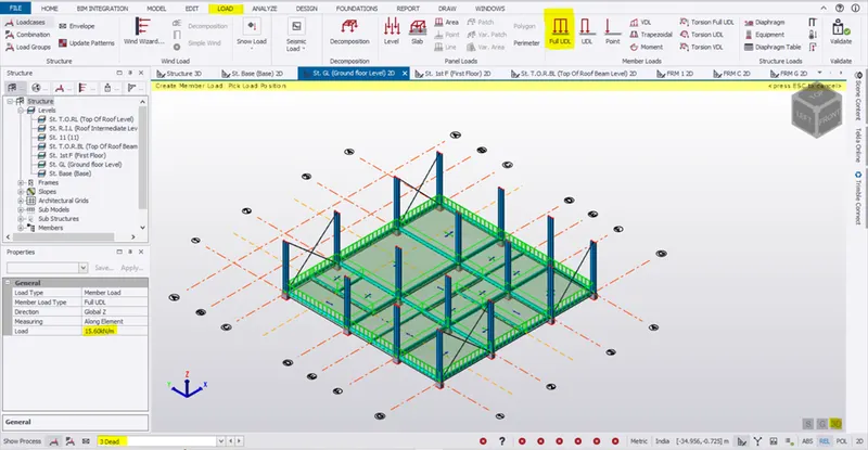
- Go to GL and apply the brick loading by selecting load -> Full UDL and entering 15.6 KN/ m in the property window and select the perimeter of the model.
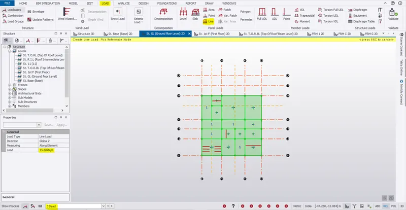
- Go to load -> Line load and enter the value and pick a reference node and draw brick loading line by referring the plan.
- Again, go to load -> Full UDL and select the remaining members in the GL.
- Toggle to 3D view and validate.
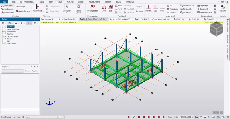
- Follow the above procedure for First floor level.
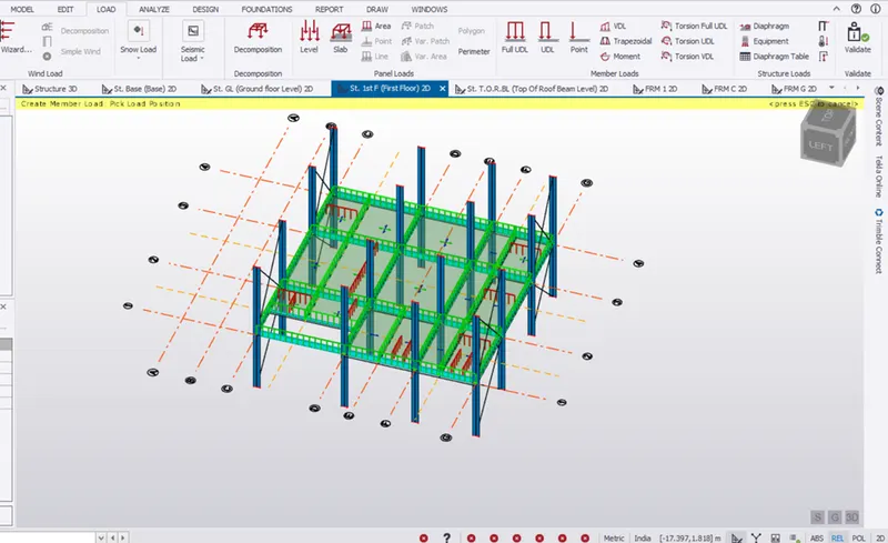
- Follow the above procedure for T.O.R.B level.
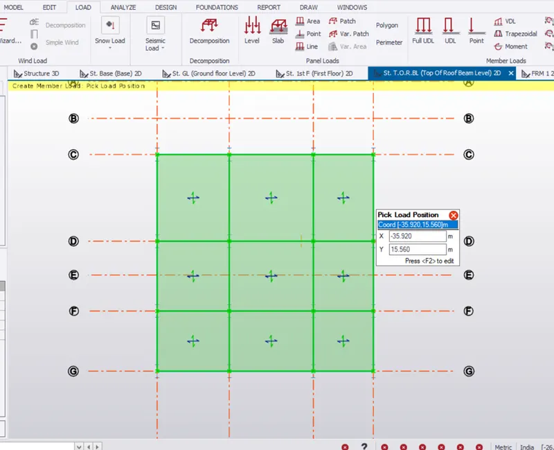
- Go to 3D view and apply roof loading by selecting load ->Area loading and enter the value in the property window.
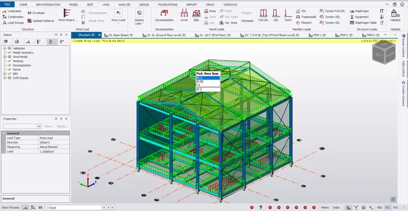
- Result:
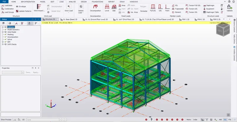
- Dead load is applied by following above steps.
2.Aim:
To calculate live load in design report based on IS code and apply live load on the model.
Given data:
- Assume the loading based on IS 875
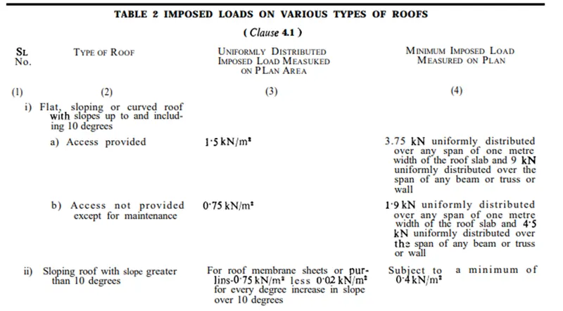
- Roof loading
- Consider equipment loading as 5KN per sq m.
Procedure:
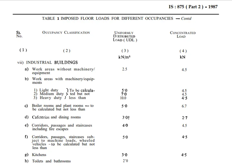
- Refer IS 875 Part -2,Table- 1 for Live load
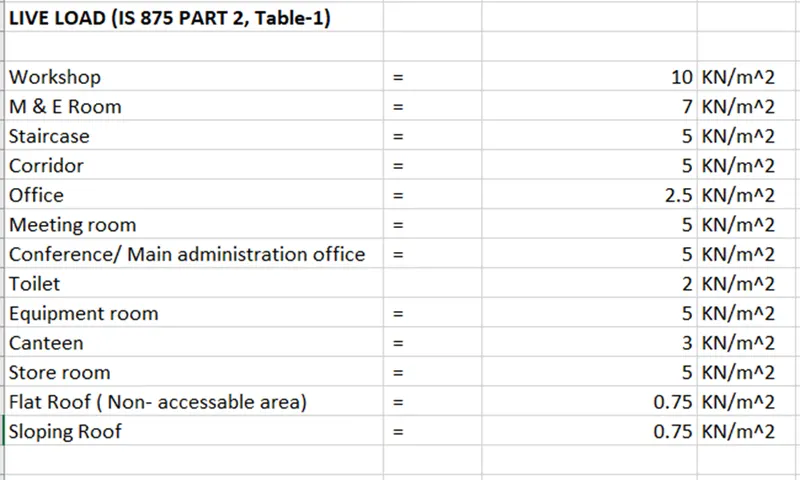
- Open EXCEL and enter the loads and values to be used in the project for easy check.
- Open TSD steel building model.
- Go to Ground level
- Select the load as imposed load in the status drop down.
- Go to Load -> Area load and click on the slab.
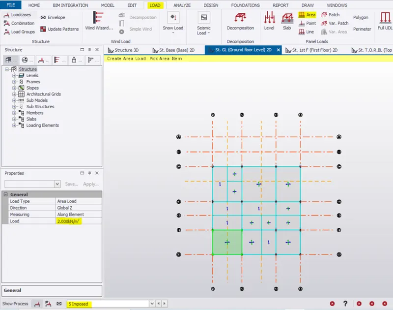
- Check the excel and enter the loading in the property window and follow the same procedure for the rest of the slabs.
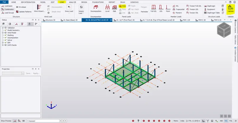
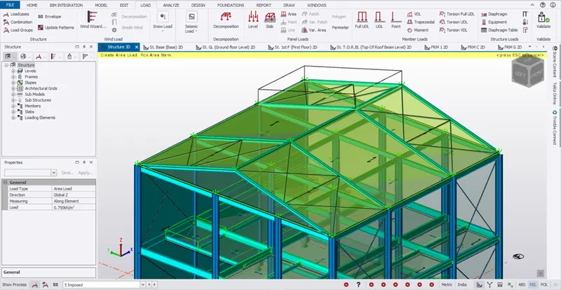
- Toggle to 3D view and validate.
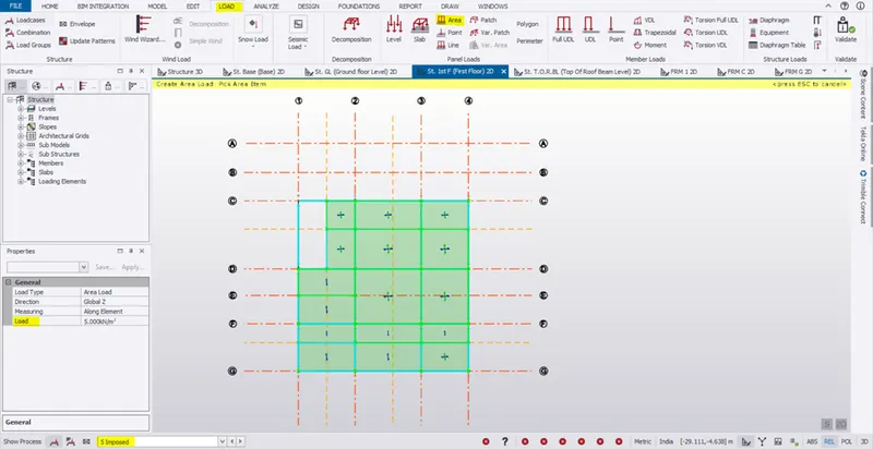
- Go to first floor level and do the loading.
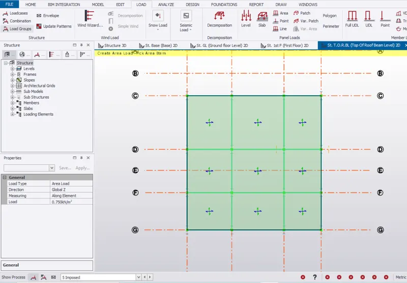
- Go to Top of the Roof Beam Level and change the loading to Imposed and assign the load.
- Go to 3D and change the loading to Imposed and apply the load on the roof.
- Result:
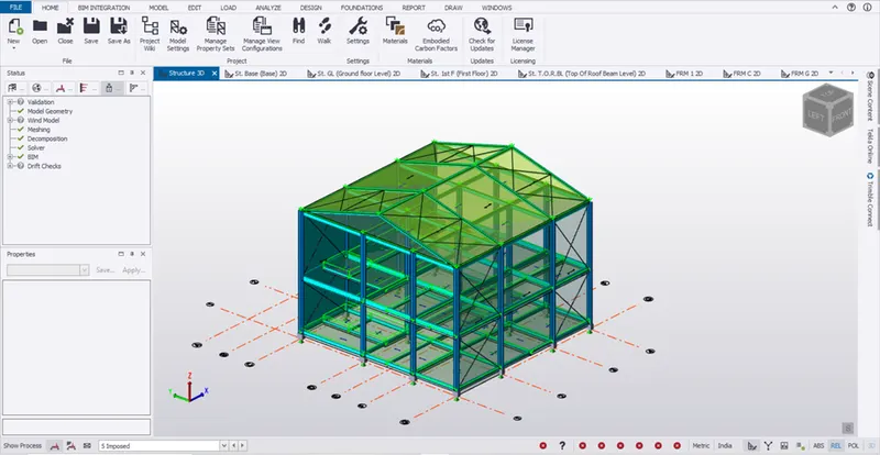
- Validated result.
- Imposed load is applied by following above steps.
3.Aim:
To generate a calculation for 5T crane loading based on given inputs.
Given data:
- Centre to Centre of wheel = 10m
- Weight of crab = 40 KN
- Number of wheels = 4
- Wheel base = 2m
Calculation:
- The approximate minimum approach of the hook to gantry girder = 1m
- Crane capacity = 5T=5000kg= 50000 N = 50KN
- No of wheels on each side = 2
- Span of Gantry girder, c/c distance between column = 7m
Maximum wheel load
- Maximum concentrated load on crane =Crane capacity + Crab weight 50 +40 = 90 KN.
- Self-weight of Crane=60 KN.
- UDL on crane =60/10 = 6 KN/m
- Ra +Rb = 90 + (6*10) =150KN
-
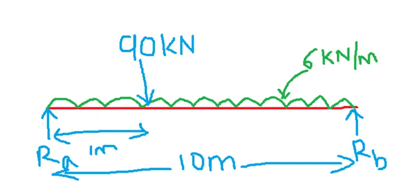
- Taking moment on b,
- (Ra*10) – (90*9) – (6 *10*5) =0
- Ra = 111KN
- Rb =150 – 111 = 39 KN
- Taking max reaction, Static wheel load= 111KN.
- This load is shared by 2 wheels, so 111/ 2 = 55.5 KN
- Adding 10 % of impact = 55.5 *1.1 = 61.1 KN
- Factored load = 61.1 * 1.5 = 91. 65 KN
Maximum Bending moment :
- Assume Self weight of the gantry girder = 1.6 KN/m
- Self-weight of the Rail= 0.3 KN/m
- Total UDL = (Self – weight of rail+ self-weight of gantry girder)= 1.6 +0.3=1.9 KN/m.
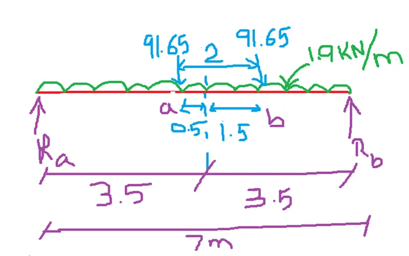
- Ra +Rb = (91.65 *2) + (1.9* 7) = 196.6 KN
- Moment at B =0
- (Ra*7) – (91.65 * 2 ) – ( 91.65 * 4) – ( 1.9 *7* 3.5) = 0
- Ra = 85.20 KN
- Rb = 111.4 KN
- Bending moment under wheel due to live load = 85.20 *4 = 340.8 KN
- Bending moment due to impact = 0.10 * 340.8 = 34.08 KNm
- Total bending moment due to live load and impact load =340.8 +34.08 =374.88 KNm
Maximum shear force in gantry girder:
- For the maximum SF in gantry girder, one of the wheel loads have to be placed on the support.
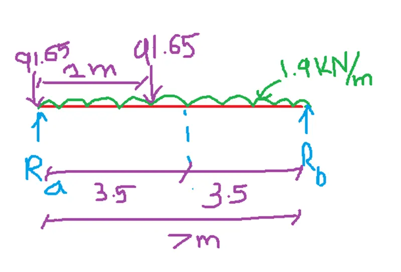
- Moment at B= 0
- (7* Ra ) –( 91.65 *7) –( 91.65 *5) –( 1.9*7*3.5)=0
- Ra = 163.76 KN
- The maximum shear force due to wheel load is 163.76 KN
Lateral force:
- Surge load along y = 10% of (crane capacity + crab load) = 0.1 * ( 50+40) =9KN
- This load is shared by 4 wheels = 9/4 = 2.25 KN
- Maximum horizontal reaction due to the lateral force by proportion at
- = Lateral force * reaction at a due to vertical load / maxiu,m wheel load due to vertical load
- = 2.25 * 85.20/ 91.65 = 2.09 KN
- At B
- 9- 2.09 = 6.91 KN
- Brake load along X = 5% of static wheel load = 0.05 * 111 = 5.55 KN
Result:
Hence the maximum wheel load, bending moment, shear force, Surge and brake load are found.