To calculate dead and live load for industrial steel structures and to apply them using TSD
- AIM:
To Calculate dead load in design report based on IS code and apply dead load on the model
- Finishes of 50mm
- Slab as per design
- Brickwall 150mm thickness
- Roofing load based on purlin size
- Ceiling loading 0f 0.3KN per sq m
Procedure:
- Launch Tekla Structural Designer
- Open the model created in the last challenge
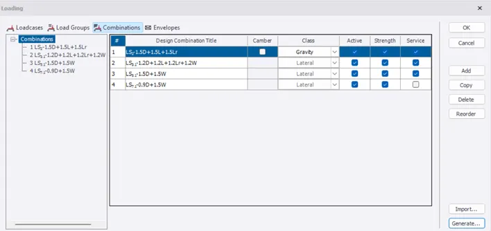
- Go to Load – Load Cases
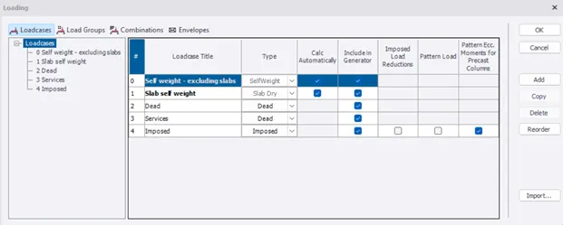
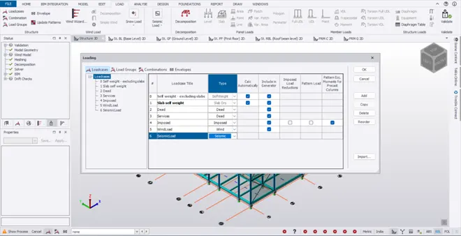
- Click on Combinations and select Generate
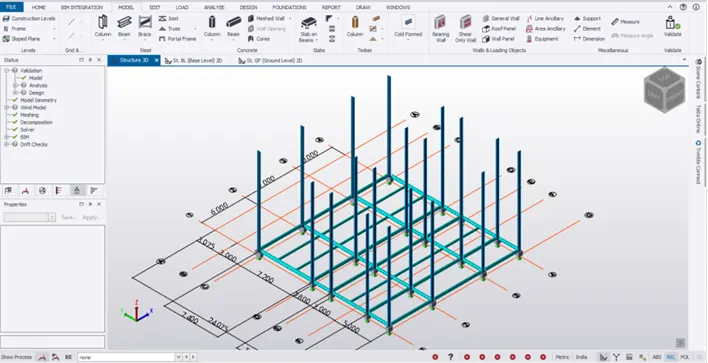
- Go by the default ‘ Delete all previously generated combinations’
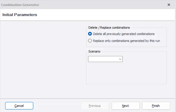
- Click on Next to view the Combinations, Services and NHF
- Finally click on Finish
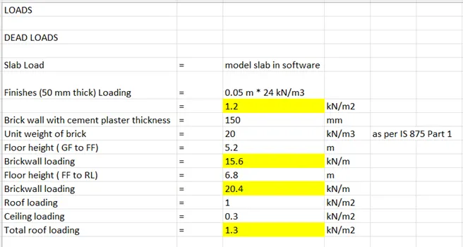
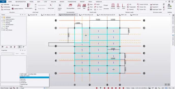
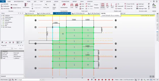
- Now we are going to apply the floor finish load of 1.2 kN/m2 to each slab
- Select Area load under Panel loads
- Change the load intensity to 1.2 kN/m2
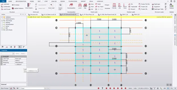
- Select each area one by one
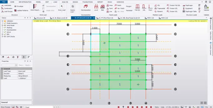
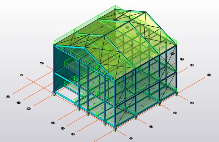
- Toggle to 3D view to check the loadings
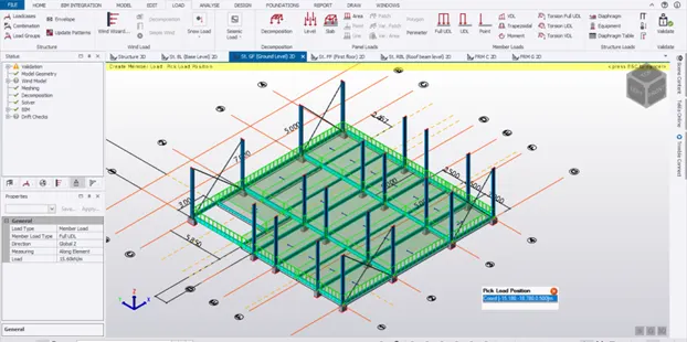
- Also under Panel loads – Line loads to model the interior brick walls according to the sketch
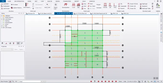
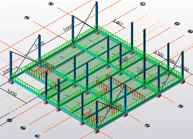
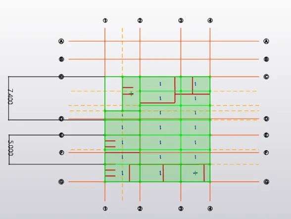
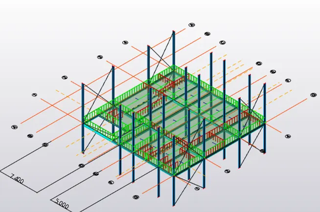
- Now go to Panel loads – Area loads
- Change the roof loading intensity as 1.3 kN/m2
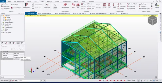
Result:
- Floor finishes loads are first applied to the GF, FF and RBL
- Brickwall loading is applied to GF and FF level accordingly
- Finally the roof loading is applied on the roof
Thus the dead loads are applied in the model
2 AIM:
To calculate live load in design report based on IS code and apply live load on the model
- Assuming the loading based on IS 875
- Roof loading
- Consider equipment loading as 5KN per sq m
Procedure:
- Open MS Excel
- The various rooms in our structure are listed one by one
- The corresponding live loads are obtained from the IS 875 Part 2 code book
- Now select Imposed load from the load cases below
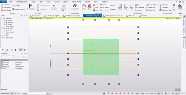
- Go to Panel loads – Area loads/ Patch to apply loadings on floors
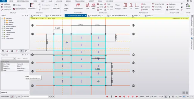
- Between grids C and D apply staircase and workshops load are applied
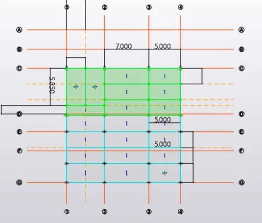
- For the area between E and F, apply meeting room loading of 3 kN/m2 (between 1 and 2) and store room loading of 5 kN/m2 in the area between 2 and 4
- Similarly check the sketch and proceed for the next set of grid lines too
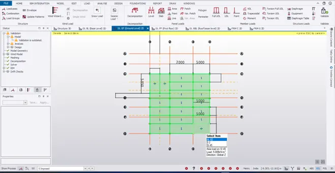
- Repeat the same procedure for FF level too
- Apply the roof loading of 0.75 kN/m2 on the RB level
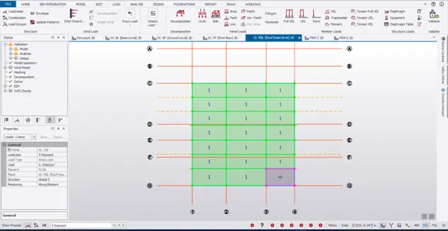
- Also apply the same loading of 0.75 kN/m2 for the roof level too
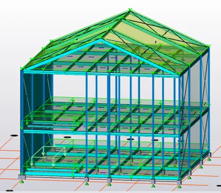
Result:
- The imposed loads are thus applied to all the floor levels and roof levels by referring to IS 875 Part 2
- While applying the imposed loads, the sketch has to be checked and accordingly the loads are applied for each panels
3.AIM:
To generate a calculation for 5T crane loading based on following inputs
- Centre to Centre of wheel = 10m
- Weight of crab = 40 KN
- Number of wheels = 4
- Wheel base = 2m
Procedure:
- Given,
- Centre to Centre of wheel = 10m
- Weight of crab = 40 KN
- Number of wheels = 4
- Wheel base = 2m
- Crane capacity = 5T = 5000kg = 50000 N = 50 kN
- No of wheels on each side = 2
- Weight of the crane = 60 kN
- Span of the gantry girder(max c/c distance between 2 columns) = 7 m
Maximum Wheel load:
There are 2 loads acting on the crane girder.
- UDL due to Self weight of the crane
- Concentrated load due to weight of the crab / trolley and crane capacity(weight lifted by the hook)
Lets find the loads one by one.
UDL due to Self weight of the crane = S.W of the crane / c/c between the wheels
= 60 / 10 = 6 kN/m
Concentrated load due to weight of the crab / trolley and crane capacity = 40 + 50 = 90 kN
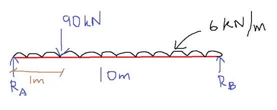
Minimum hook approach = 1m
Applying the equilibrium equations,
Ra + Rb = 90 + (6* 10) = 150 kN
∑M b = 0
(10 * Ra) – ( 90 * 9) – ( 6 * 10 * 5) = 0
Ra = 111 kN
Rb = 150 – 111 = 39 kN
Max reaction is taken always
Ra = 111 kN = Static wheel load
This load is shared by 2 wheels , Load transferred by 1 wheel = 111/2 = 55.5 kN
Adding 25% for Impact = 69.4 kN
Factored load = 69.4 * 1.5 = 104.1 kN
Maximum Bending Moment:
Assume self weight of the gantry girder = 1.6 kN/m
Weight of the gantry girder = 0.3 kN/m
Total UDL = 1.6 + 0.3 = 1.9 kN/m
For maximum BM, the wheel loads should be kept so that the C.G of 2 wheel loads and the wheel loads recline equidistant from the centre of the span
i.e Max BM occurs under wheel load ‘a’ when centre of the span is at equal distance from the wheel load and the C.G of the wheel loads
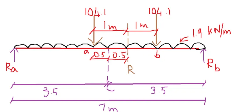
Ra + Rb = (104.1*2) + (1.9*7) = 221.5 kN
∑M at B = 0
(7 * Ra) – (104.1 * 2) – (104.1 * 4) – (1.9 * (7^2) / 2 ) = 0
Ra = 95.96 kN
Rb = 125.5 kN
Max BM at a = (95.96 * 3) – (1.9 * 3^2/2) = 279.33 kNm
Maximum Shear force in gantry girder:
For the max SF in gantry girder, one of the wheel loads have to be placed on the support
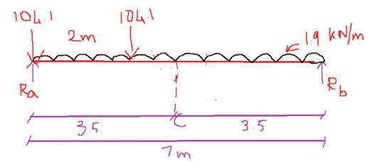
∑M at B = 0
(7 * Ra) – ( 104.1 * 7) –(104.1 * 5) – (1.9 * 7^2 / 2) = 0
Ra = 185.1 kN
Lateral force:
Surge load along y = 10 % of (crane capacity + crab load) = 0.1 * (50 + 40 ) = 9 kN
This load is shared by 4 wheels = 9 / 4 = 2.25 kN
Finding the BM for this load,
104.1 -à 279.33 kNm
2.25 -à ( 2.25 * 279.33) / 104.1 = 6.03 kNm
Brake load along x = 5 % of static wheel load
= 0.05 * 111.1 = 5.56 kN
Result:
- The maximum wheel load is found by finding the reaction of the supports of the crane girder
- The maximum BM is found by arranging the wheel loads in such a way that the centre of the span lie equidistant from the wheel load and C.G of the wheel loads
- The maximum SF is found by placing the wheels directly on the support
- Then the surge loads and brake loads are found out