To Analysis and Design of Steel Structures using TSD
1. AIM: Summarize your study for the bending moment, shear force and deflection diagrams for the elements of the mode
PROCEDURE:
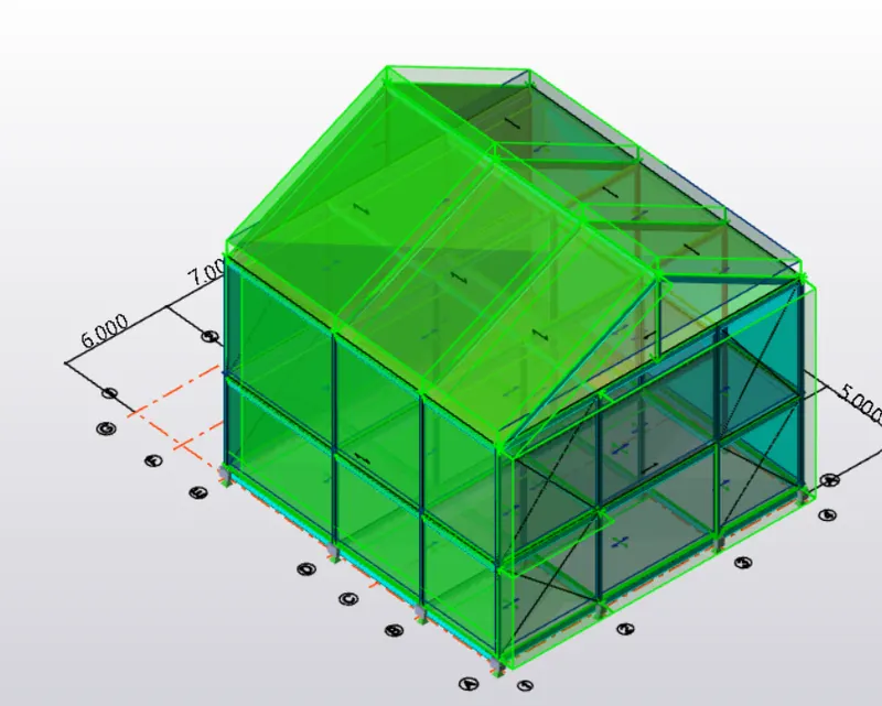
• Initally open the Tekla file you saved prviously Seismic data in the structure
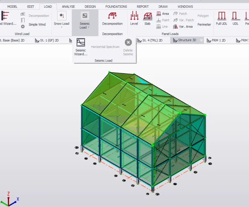
• To set->go to Load panel->Under seismic load go to Seismic wizard
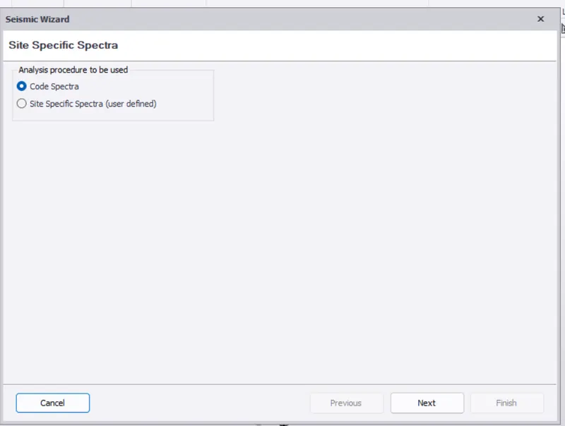
• Select the code spectra->Next
• A new tab opens->Check the base information of the model
• Check seismic zone and site->Click next
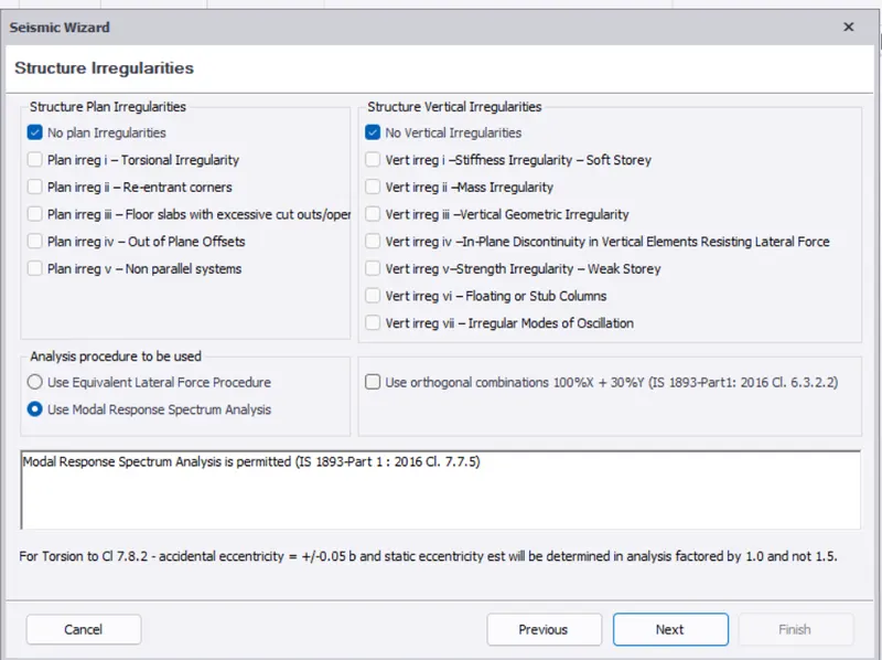
• Now set the structure irregularities->If any plane or cliff give
• or else click next
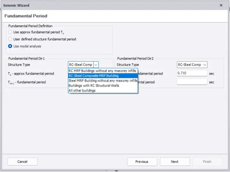
• on the Fundamental period->select structure as RC steel composite
Click on Next
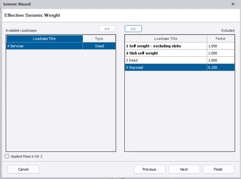
On the next tab - exclude the service load and select all other and click next
• Select the seismic combination->click next
. Click om finish
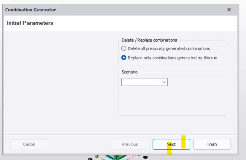
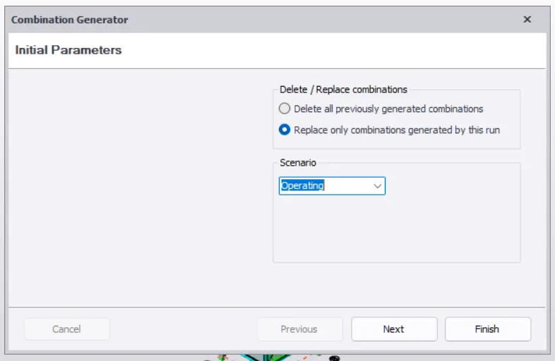
• Now go to load combination->click on generate
• Click next and select the load combination and finish.
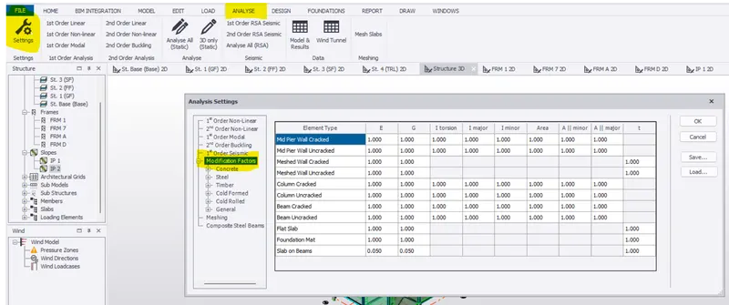
• Now before starting the analysis we check the factors
•Go to Analyse tab->Go to settings
• under the modification factors tab >select steel
• check for tall the factors to be 1.0
• you can modify the factors if needed
• Now to analyse the strcutre->click on 1st order analysis
• After select the combination and cases you want to analyze
• click on Ok
• Aftfter the analysis is done ->go toresult view from the bottom right corner
Now to analyse the strcutre->click on 1st order analysis
• After select the combination and cases you want to analyze
• click on Ok
• Aftfter the analysis is done ->go to result view from the bottom right corner
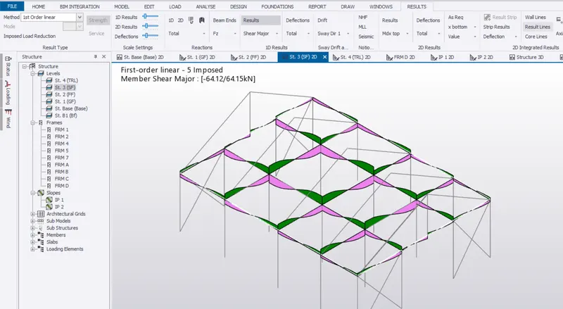
. On the result panel->Go to result >moment Major->Select the axis
• It'll show the results of the bending Moment Major
These are the loads of Effective
Imposed load
• Now check for the frames
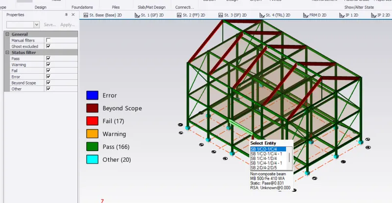
• For now open frame
• The frame ->The beams shown in red has failed so we try to check the member
• select the beam->right Click->Check member
• Click on check member->a list is shown here the crictal failure of beam in moment major
• So we try changing the beam section to MB400 (Previously MB300)
• After trial and errors we rectify the error by giving the section of MB500 to the beams
• similarly we check the other members and change the sections or areas accordingly
Similary do it for all other members and check for the errors
2
AIM:
Based on the analysis design the members and outline the thought process in selecting the member sizes along with the foundation design
PROCEDURE
• Now for the design of the foundation under the columns Go to the foundation tab
• Open the base level -> Under thefoundation panel click on pade base foundation
Select the pad base foundation->Click on the column under which you want the foundation to be placed.

• Select the column ->Right clickand check members ->This foundation is failing under bending capacity
• So we try to increase the area of steel provided
• Providing 25mm dia bars with 300mm spacing and increasing the depths
The dimension of foundation is 2500mm both in X&Y direction and depth 850mm
we again check the foundation and the errors are removed
• Similaryly we provide foundation to all other columns
Select the foundation->copy and apply to all other columns.
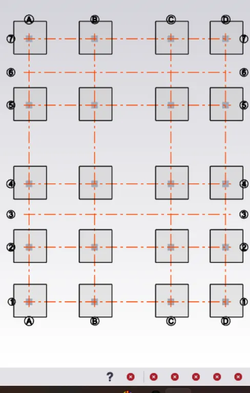
• Check the foundation for the errors
• All foundation are check there are no shown errors
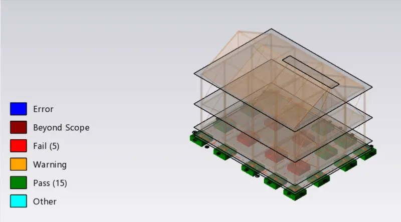
RESULT:
• Successfully desgined the foundation and the beams
• removed the errors of the section which were failing under the critical
loads