Structural Modelling using Etabs 2018
Aim
Model the g+ 7 residential building with the given architectural reference drawing typical floor plan is given in the attachment and model as per the IS codes with the reference notes given in the question.
Procedure
Open the e tab software.
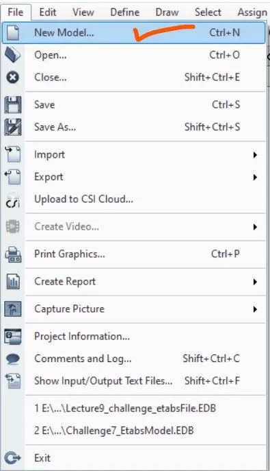
The reference of the given attachment set the grid setting and storey setting as per it.
Below image shows the grid settings and storey setting.
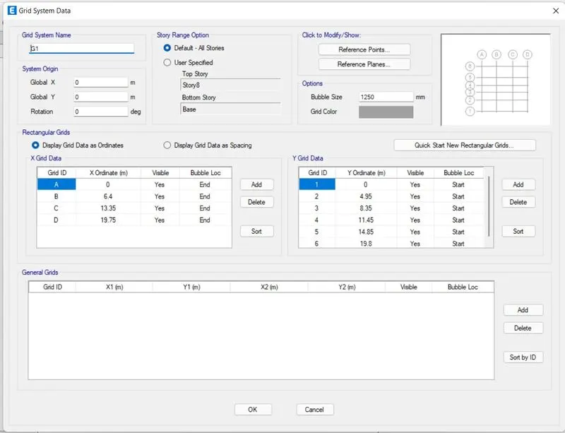
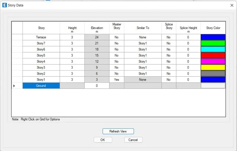
After this we have to set the material in the material property dialogue box
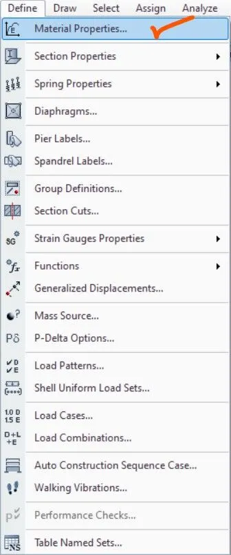
Set M25 material for the concrete grade
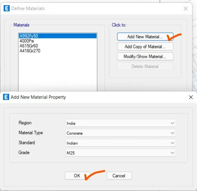
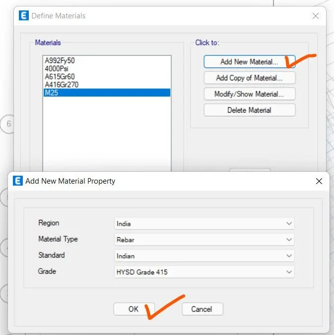
And for Rebar HYSD Fe 415 and Fe 500
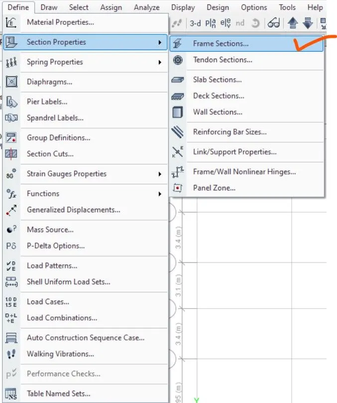
Now we have to define the section property for the column and beam section
So we have to add the new property option
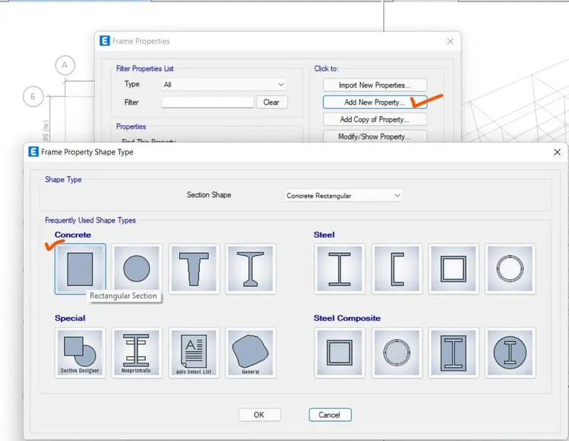
We have to modify rebar property option in beam as fe415 for confinement bar and fe500 for longitudinal bar
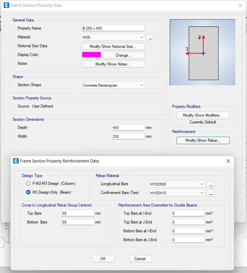
Same way we have to select for beams and columns
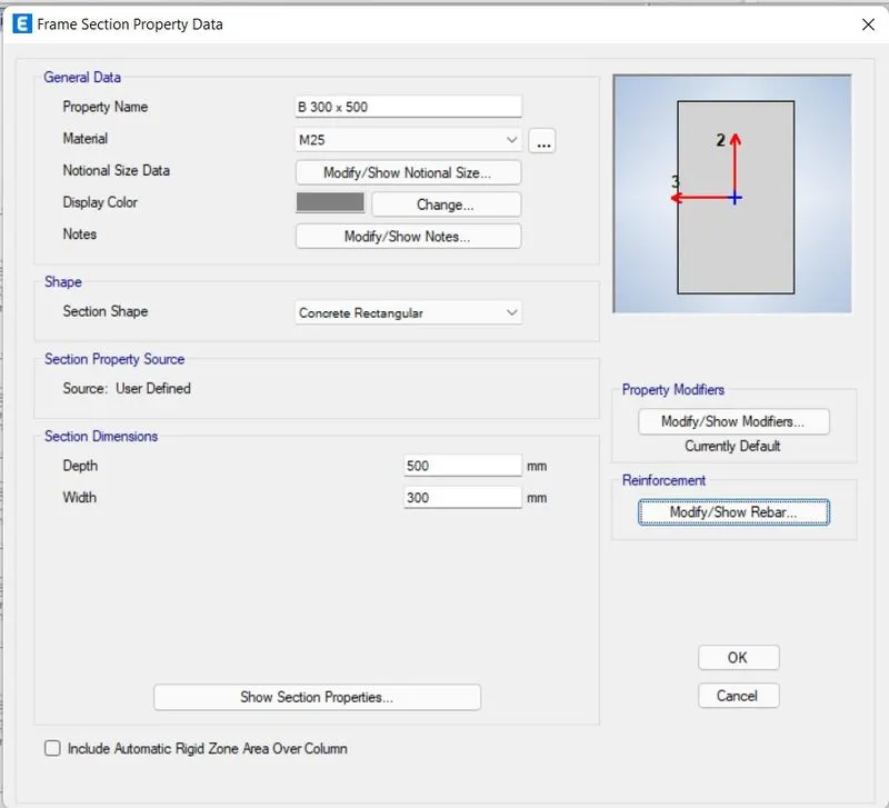
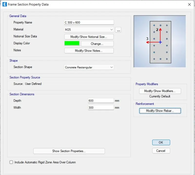
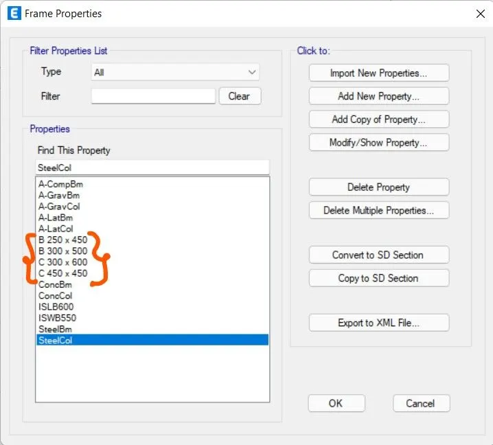
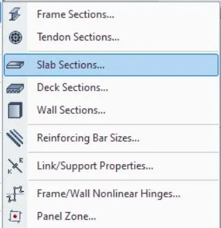
Now we have to create the slab property as the thickness 120 mm and set the property as membrane
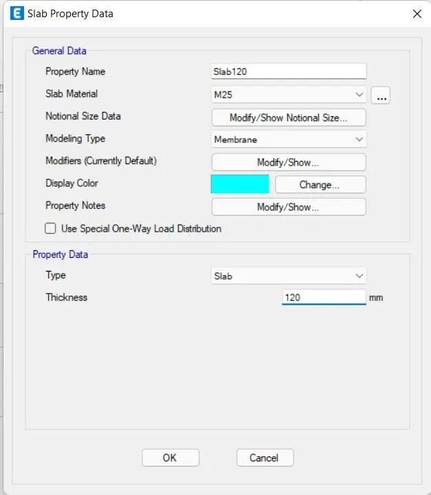
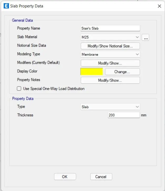
We have to also create the different slab property for stairs as 200 mm thickness.
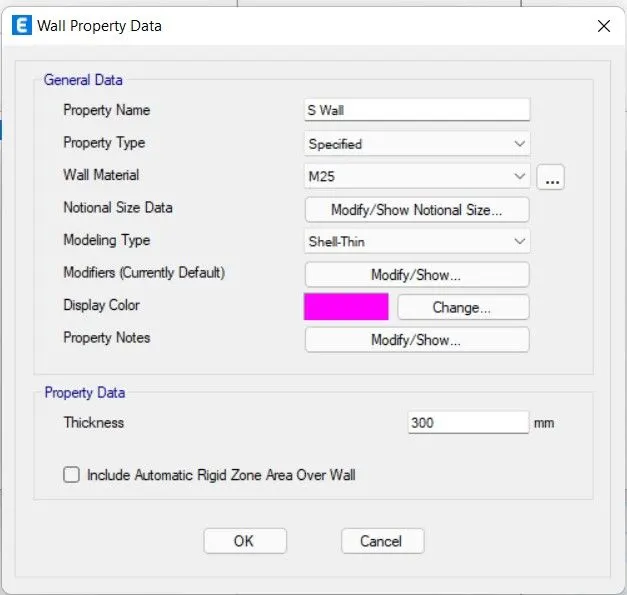
Now we have to modify the shear wall and property as thin shell of 300 mm thickness.
Now we can start model the structure in etabs software.
We can first start with the column by placing it with quick draw columns option
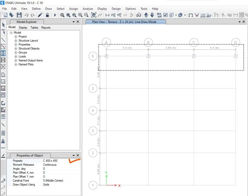
The column arrangement can be adjusted in such a way that the periphery column is of different size than the inner one.
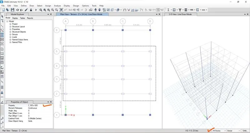
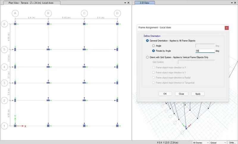
After this we can start model the beams by using quick draw beam option
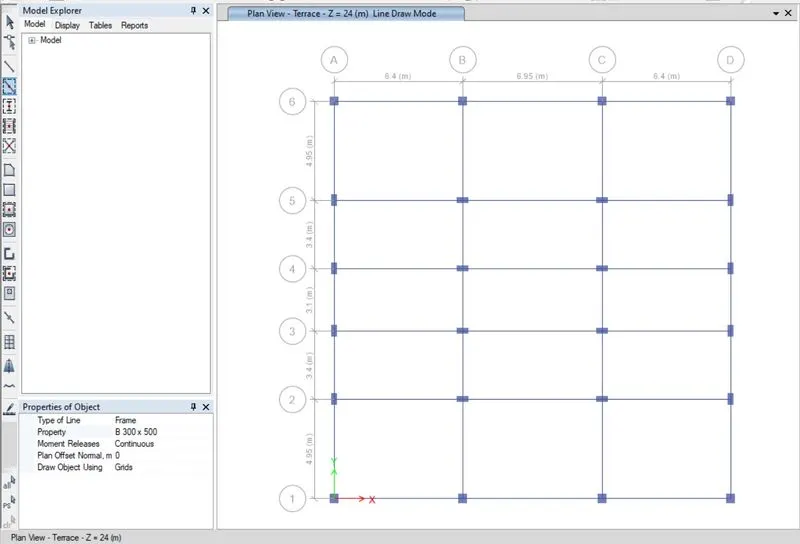
We also need to model the secondary beams
For this we need to use replicate and move command in the edit option
We can draw beams by using the same options
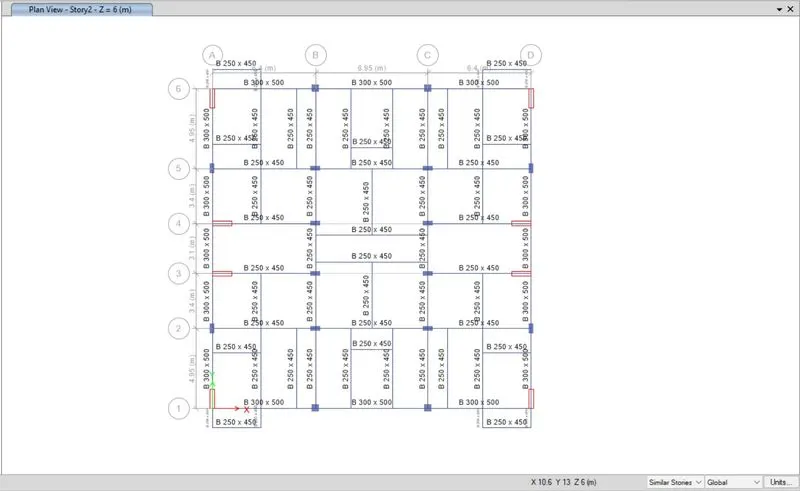
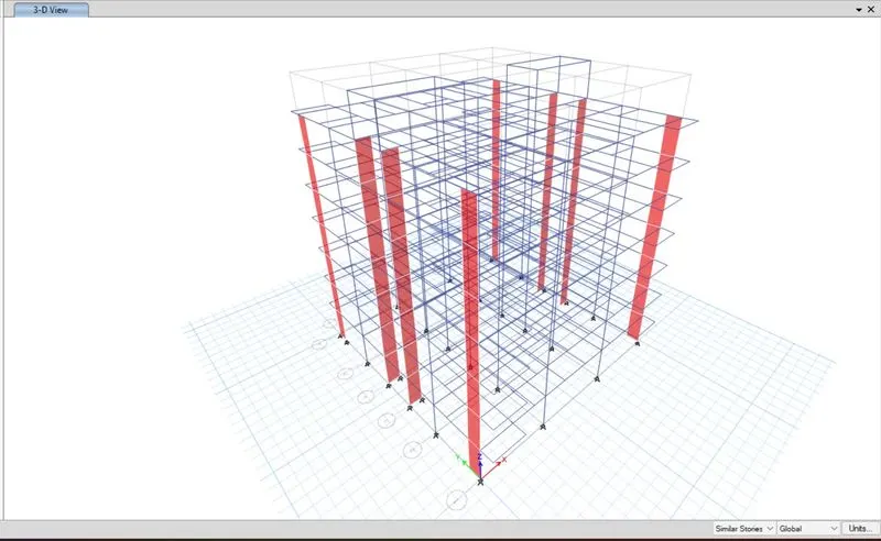
Now we can start placing the slab by using quick draw slab command
We can break the slab at the intersection of the secondary beam by using the edit option
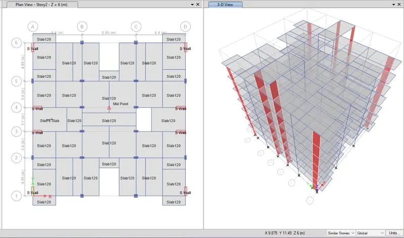
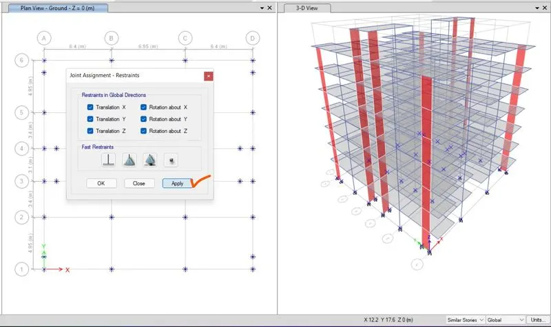
Now by selecting the base joints and restrain it by fixed support
Now we need to create a load patterns
We can say add Dead load, live load, brick wall load, floor finish and earthquake load in X direction and y direction.
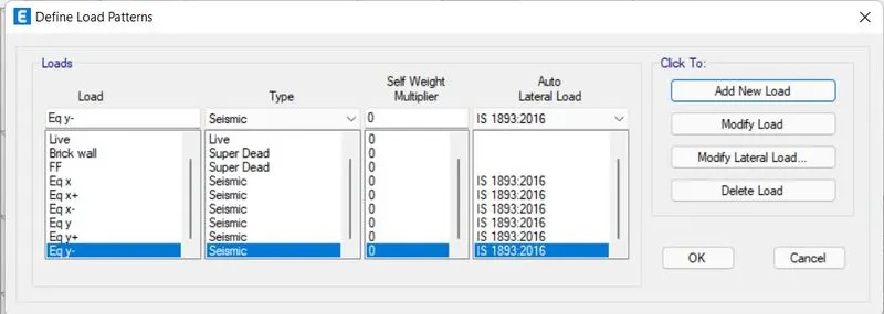
We also need to add the setting for the EQ in both X and Y direction
Time period T can be clculated by the formula given in IS code as T=0.09*h/sqrt(h)
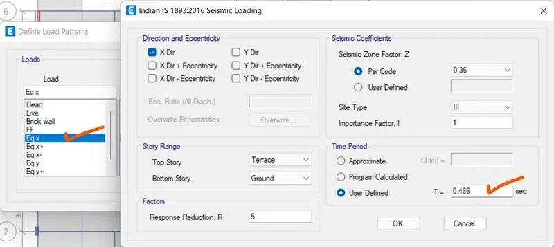
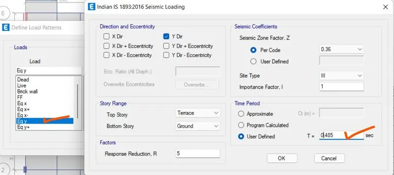
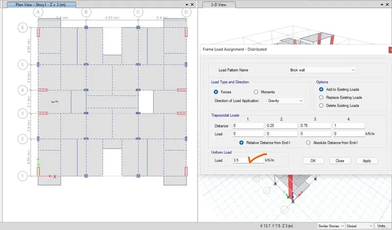
Now we need to assign the brick wall load on the beam as 3.5 kilo Newton for the AAC block
And same process for the other
The same way we can assign the shell load to the slab as 3 kilo Newton per metre square fore lift area and toilet space rest of others we can apply 1.2 to 2 kilo Newton per metre square as per IS 1893.
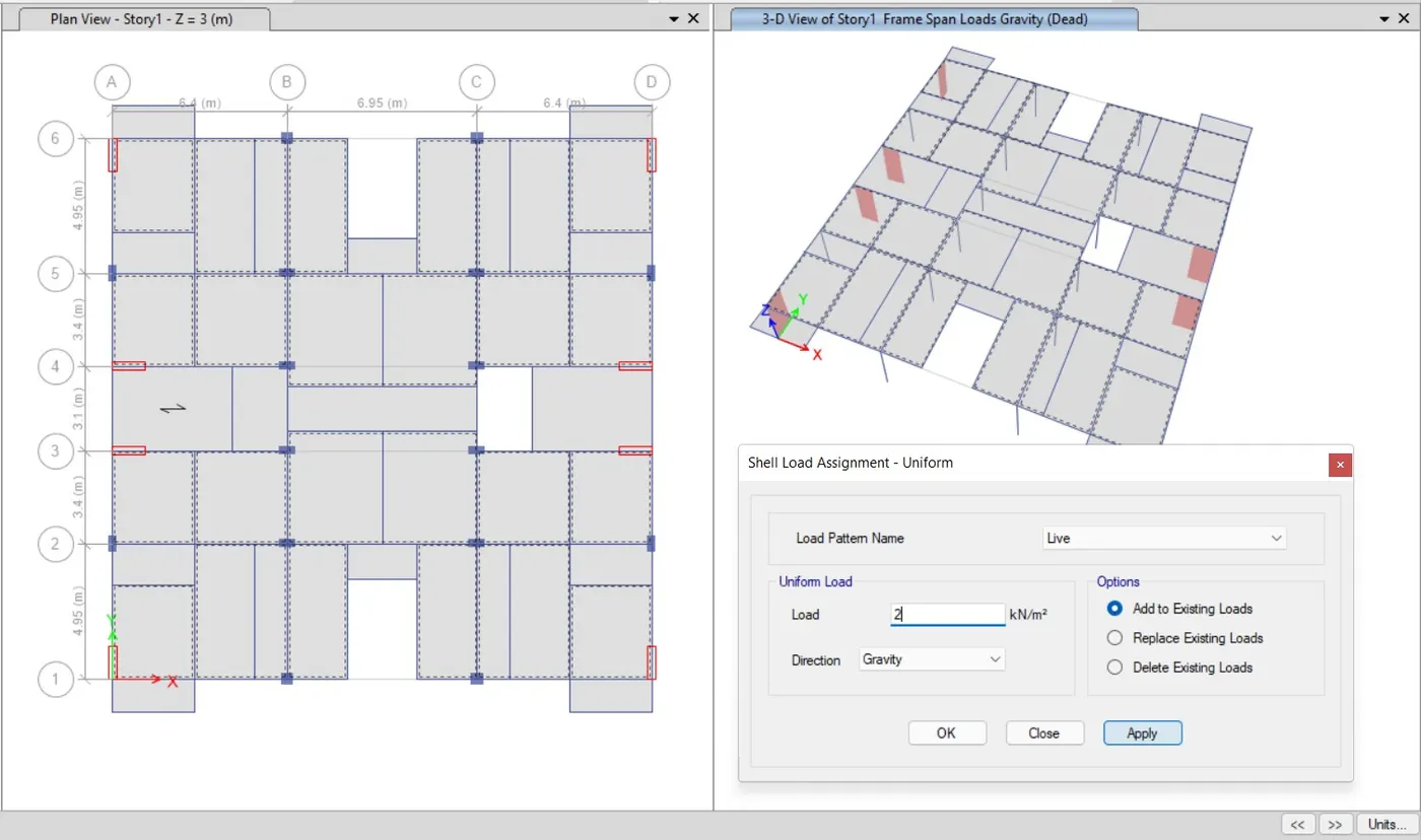
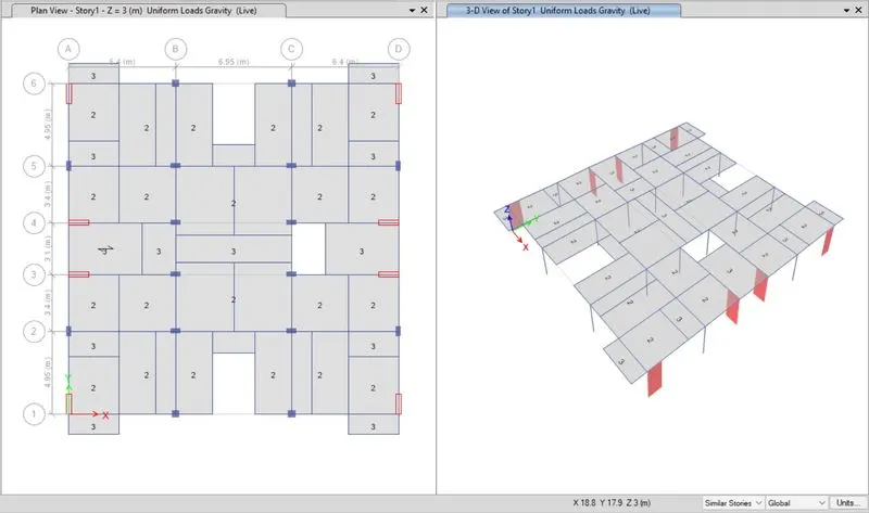
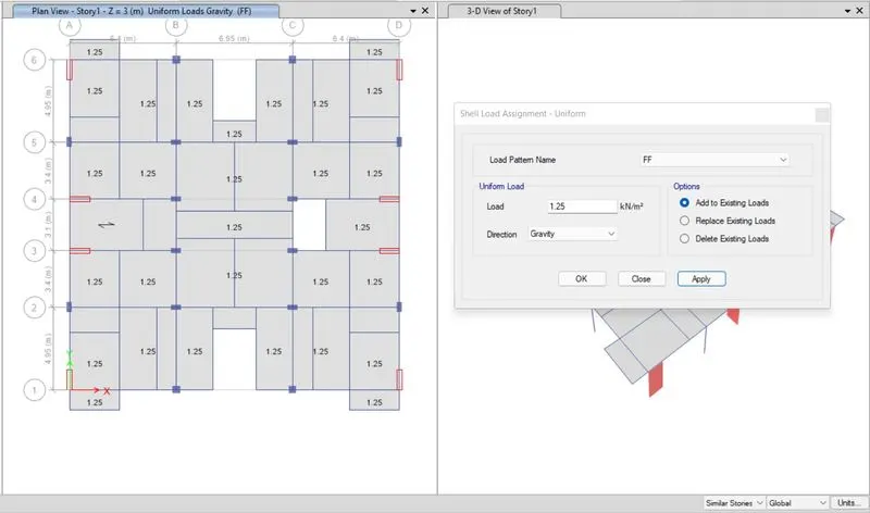
Now we have to select the live load reduction factor as given in the IS code
For first and second floor the live load reduction factor will have no change after that we have to decrease it by 0.1 as given in IS code
Now we need to add the pier lable for the Shear wall
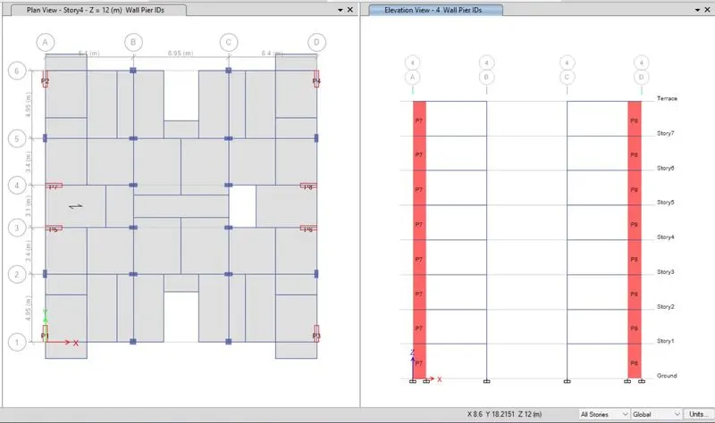
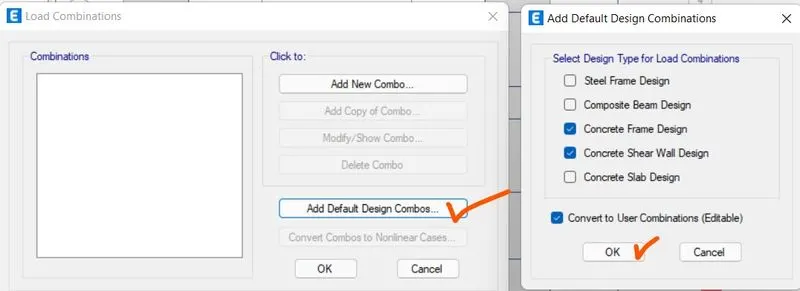
Now generate the load combination for the concrete frame design and shear wall design.
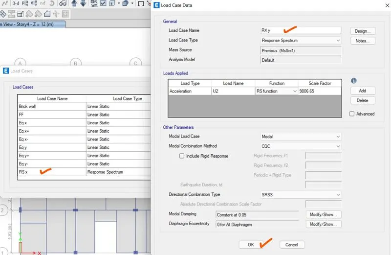
Now we have to create the response spectrum analysis for X and Y direction
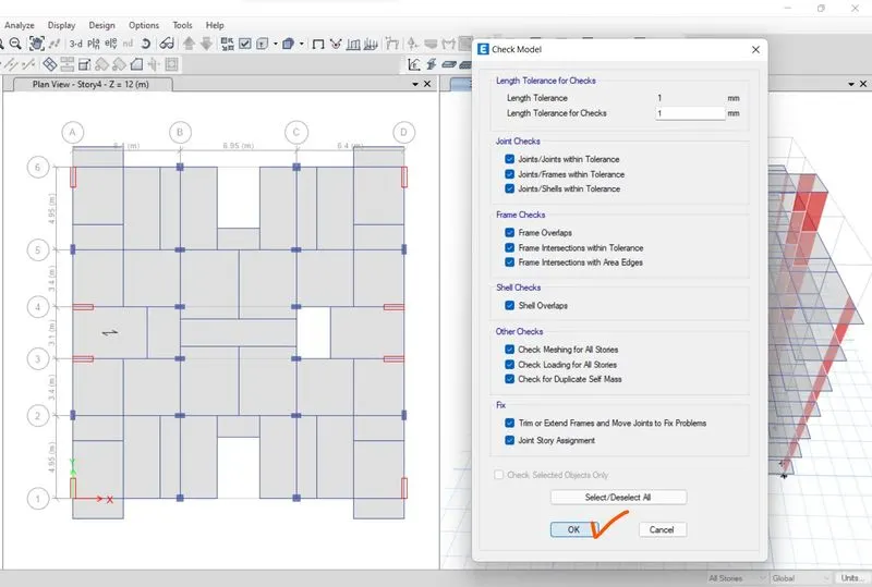
Now we have to check the model. And done the analysis.
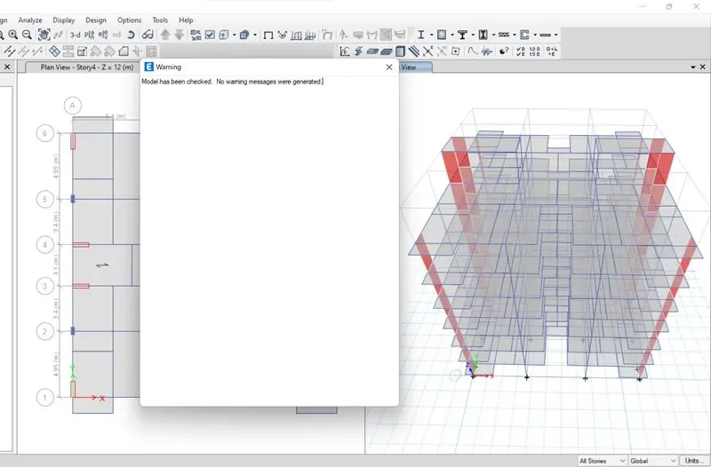
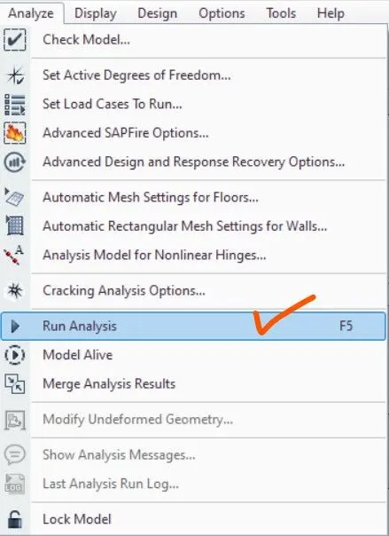
Now we have to run the analysis for the given model.
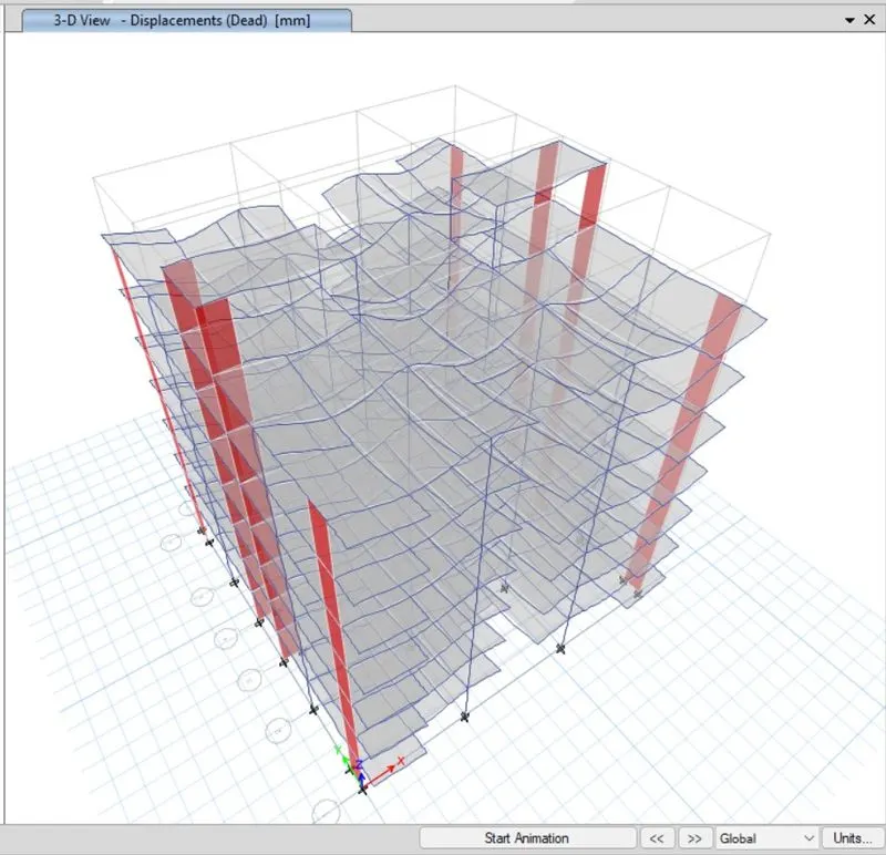
Model after Analysis
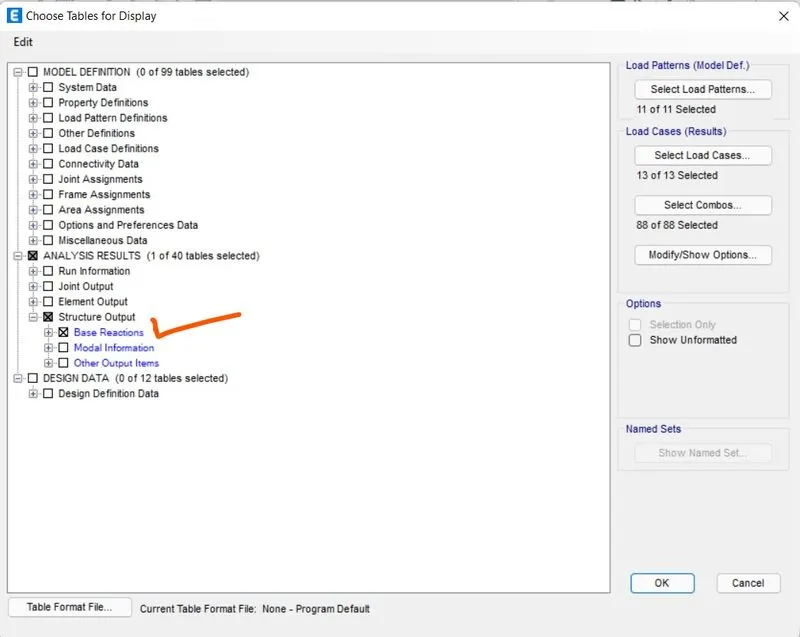
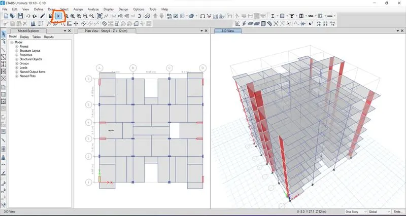
After analysis. Now we have to check for the base reaction.
Below image show the path of the table for base reaction.
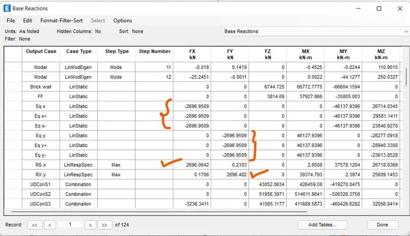
Now we have to check.
Weather the Earthquakes earthquake base reaction and response spectrum base reaction need to be equal.
Below image shows that the value differs from each other. So to make them equal we need to multiply the factor.
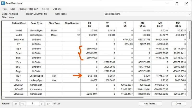
By dividing the (Earthquake load /Response spectrum)
We get the multiplication factor.
Show the scale need to be corrected for the response spectrum.
By correcting the value of the scale in RS
we need to run the analysis again
After correction we get Nearly the same base reaction value for both RS and EQ in both X and Y diection
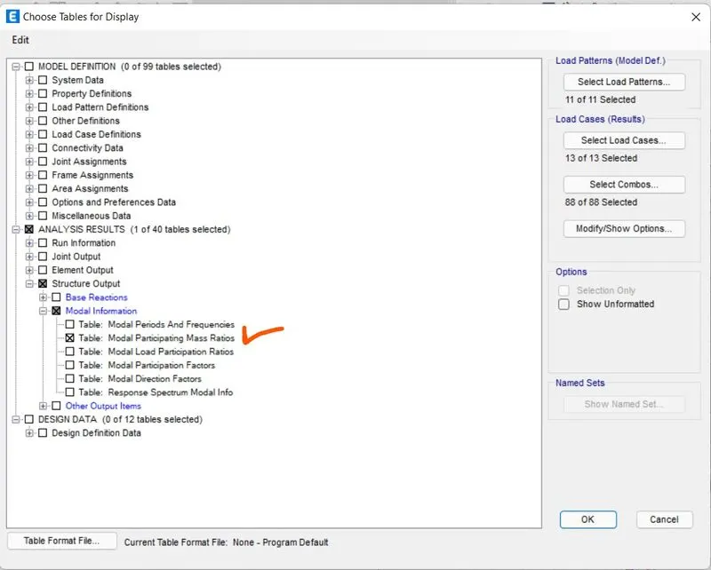
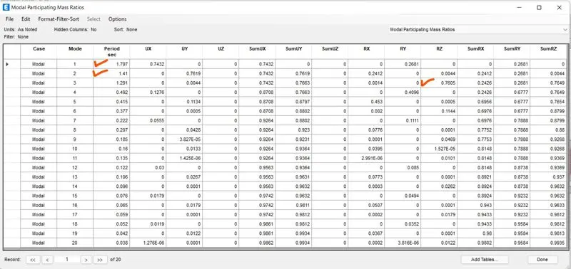
Now we have to go for the modal mass participation ratio.
The difference between the first mode and second mode is as per IS code provision.
That min. 10% difference between the time period of mode 1 and 2.
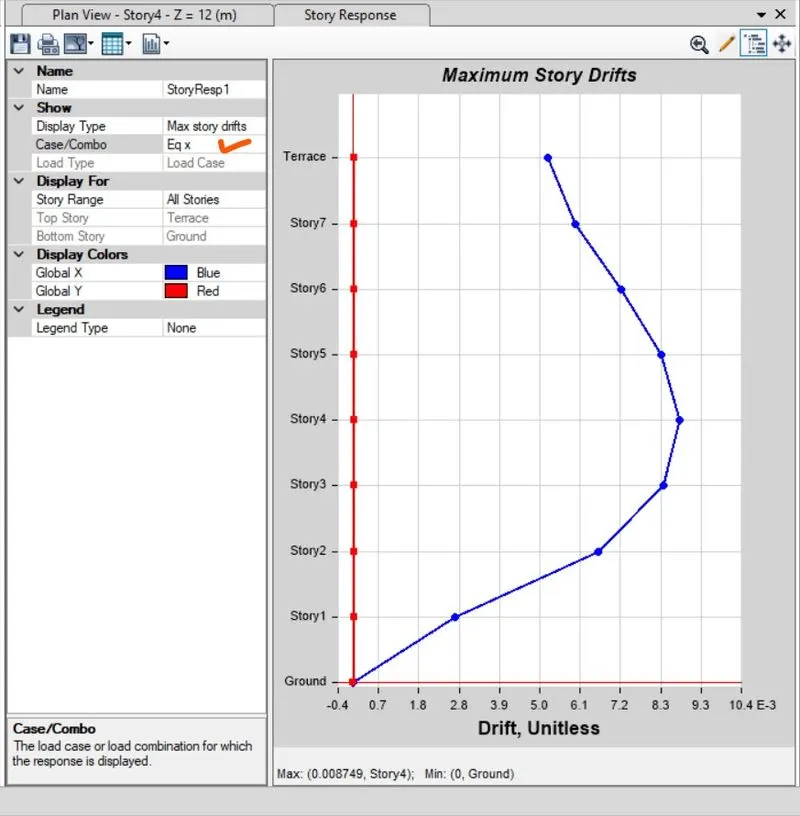
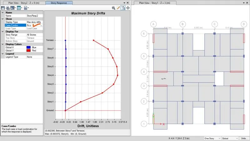
Now check for the story drift.

Here we can see that the Drift is greater than 0.04% in both X and Y directions
For EQ x
For EQ y
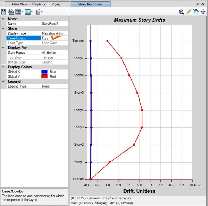
So we have to revise the model and such an arrangment for the shear wall or for other strutural members.
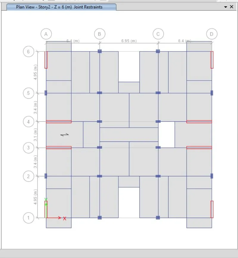
We have change the length of the shear wall from 1.2m to 3m in X direction & 2m from Y direction.
The below image shows the plan view.
New revised Plan
Result after the revised arrangment in the plan.
It satisfied the criteria of the IS code
For EQ x
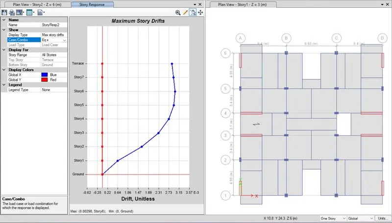
For EQ y
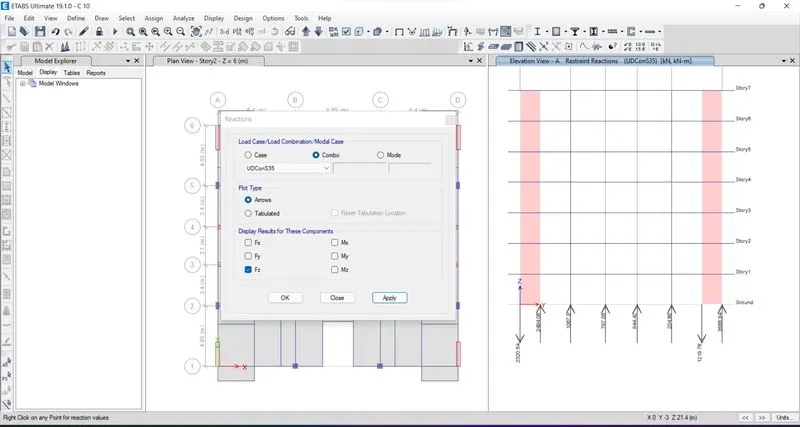
The base reaction also satisfied the ratio of the 80% in shear wall.
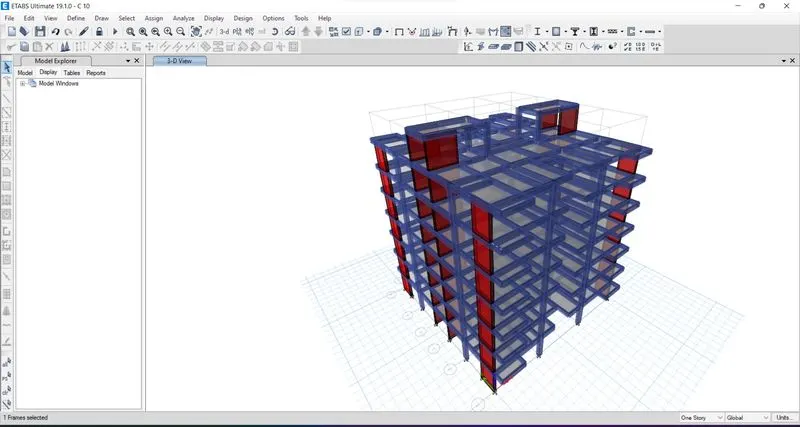
Result
We have model the struture as per the given attachment file and with taken care of the IS code provision.
Done Modal response spectrum analysis and check analysis results of the etabs model for inter-storey drift requirements, vertical & planar irregularities, minimum shear wall requirements.
Give the final plan that pass all the check.