Structural Modelling using Etabs 2018
Question
The architectural drawings for a G+7 residential building in zone 5 has been provided. The floor plan is the same for all 7 floor levels. Possible column positions have also been provided.Conceptualize a framing plan layout and then model the building in Etabs. The following architectural drawings have been provided:
- Typical floor plan - The location and thickness of the brick walls and the use of the
space (for estimating live load) can be obtained from this plan - A building section through the staircase and lift core is provided
- Parking layout in the ground floor – the column/shear wall arrangement must not
obstruct entry/exit of vehicles.
The following loadings are to be taken into account:
- Brickwall made of AAC blocks
- Finishes – floor tiles of 75 mm thickness
- Live loads as per IS 875 part 2
- Water tank of 20 KL above the staircase at Mumty level
- Lift Machine room at mumty level above lift core
The structural model must comply with provisions of IS 1893 and IS 13920.
Run a modal response spectrum analysis and check analysis results of the Etabs model for inter-storey drift requirements, vertical & planar irregularities, minimum shear wall requirements,maximum axial load ratio for column and shear walls, effective moment of inertia for beams and columns etc.
Answer
Aim:
To model an apartment with all seismic consideration, based on given architectural input and to know how to check the seismic performance of an apartment using ETABS
Introduction:
To model and analyse the G+7 residential building with the given architectural drawing using ETABS
Data required for Etabs analysis:
- Pinned support,Base + 9 story (ground to terrace) + 1 mumty
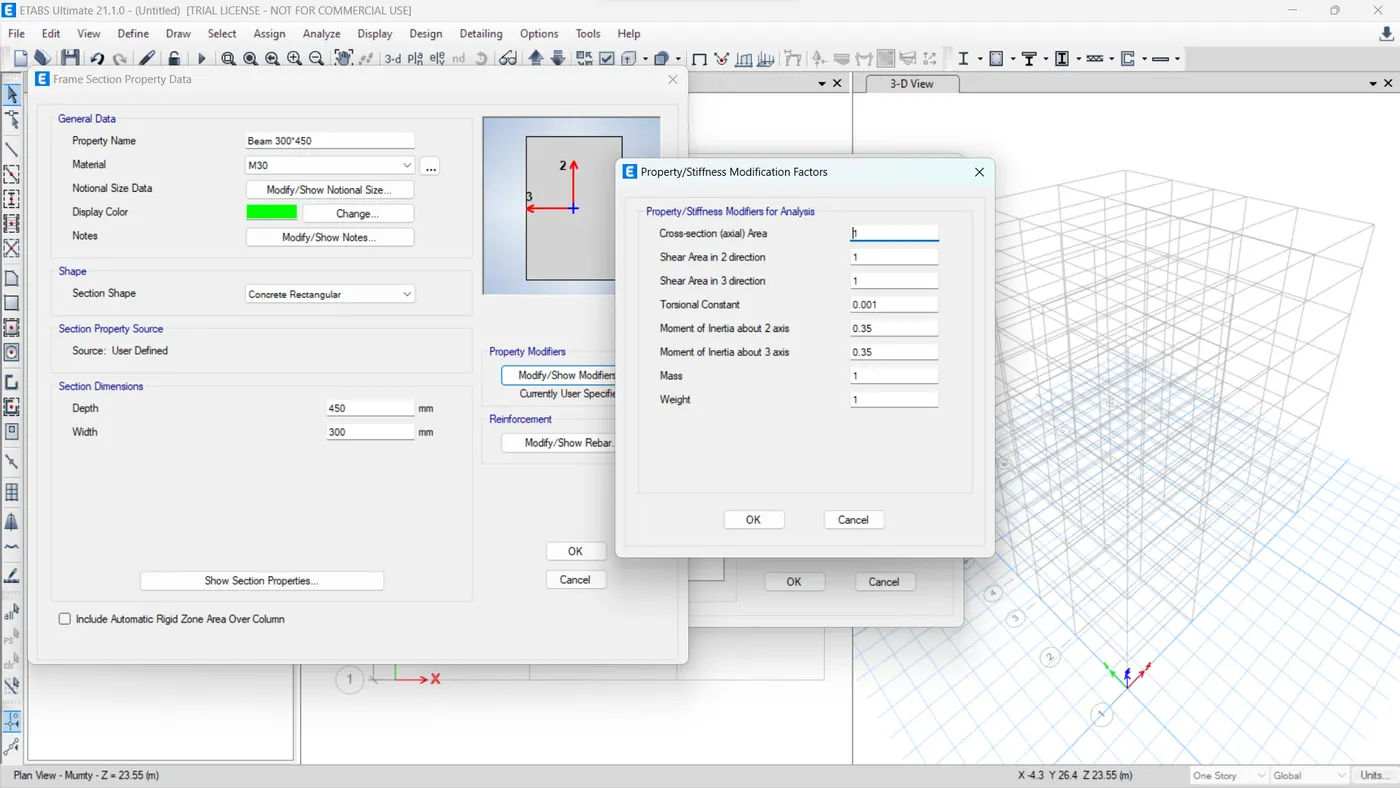
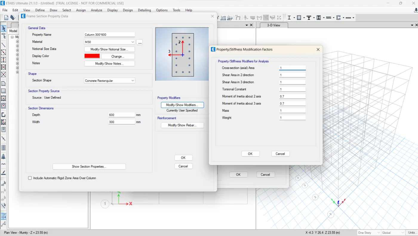
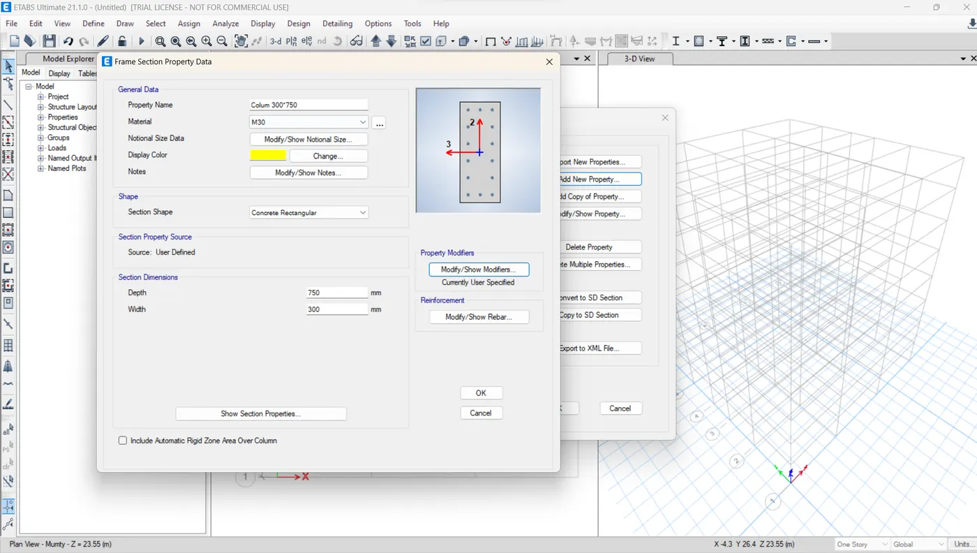
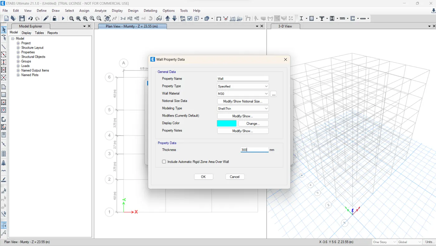
- Column 300x600mm & 300X750,Beam 300x450mm,Slab 150mm thick,Shear wall 300mm thick
- Live load 2kN/m2,Floor finish 1.5kN/m2,Wall load 3.5kN/m,Water tank 20KL over mumty equivalent to 200KN overall load
Conceptual design consideration before analysi:
- Re-entrant and cut-out check and modification (compromise)
- Vertical irregularity (soft story)
- Planar irregularity (looks symmetrical)
- 2% shear wall area with respect to build area
- Stiffness modifier for column,beam & shear wall (0.35 for beam, 0.7 for vertical)
Key point to remember while modeling:
- No slab, no wall load in ground floor
- Proper end releases in beams as per engineer intent
- No interior wall load in terrace
- Comparison of static and dynamic forces and revising the factor
Procedure:
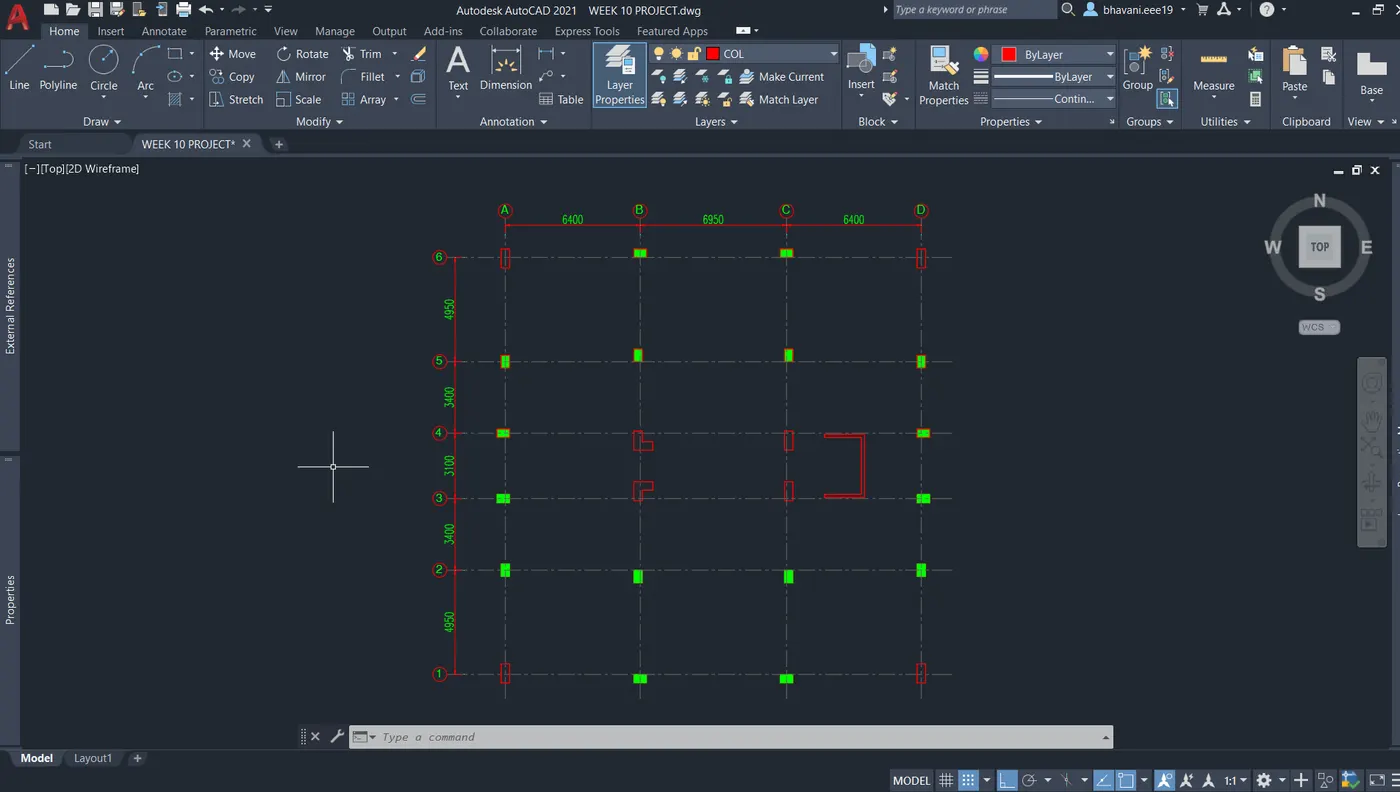
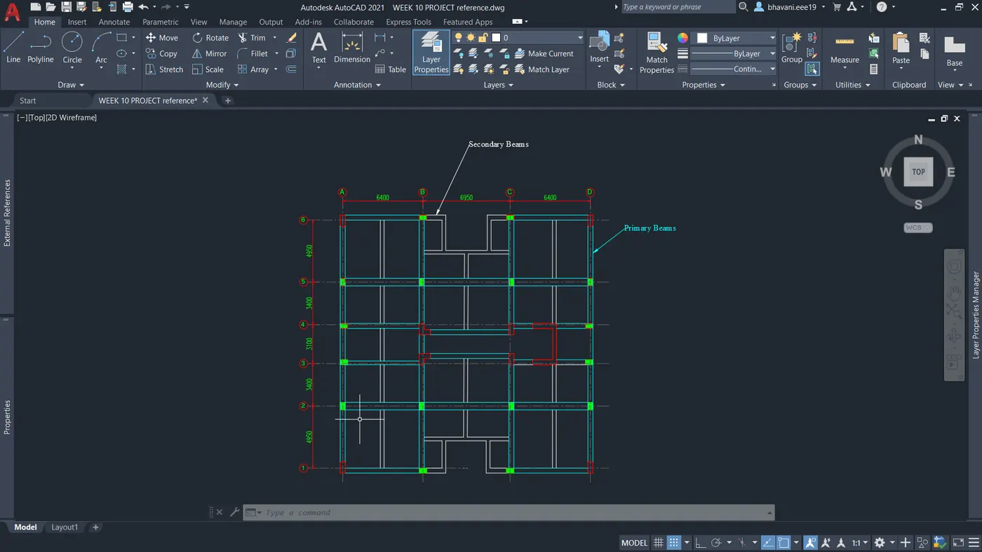
Step 1) Create Model Reference in AutoCAD
- Changed the column size, position & orientation without disturbing the parking area and floor area, it doesn’t affect the floor area and parking area
- Created shear wall according to my opinion
- This drawing is used as a reference drawing for etabs model
- I have overlapped the floor plan to the new designs plan
Step 2) Create New Model in ETABS
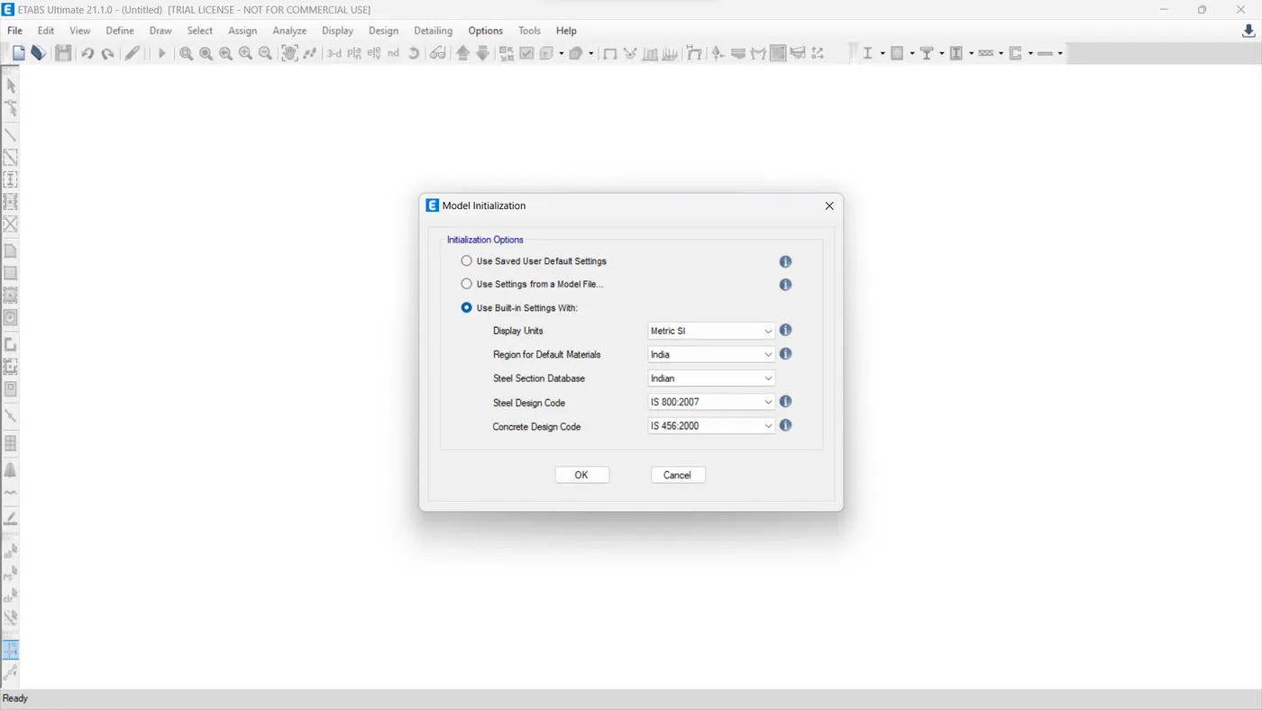
- Click on New Modal from ETABS home interface
- Select Unit Built in Setting from Modal Initialization dialog box
- Change display unit as METRIC SI
- Region for default material as INDIA
- Steel selection database INDIAN
- Steel design code IS-800:2007
- Concrete design code IS-456:2000 enter OK
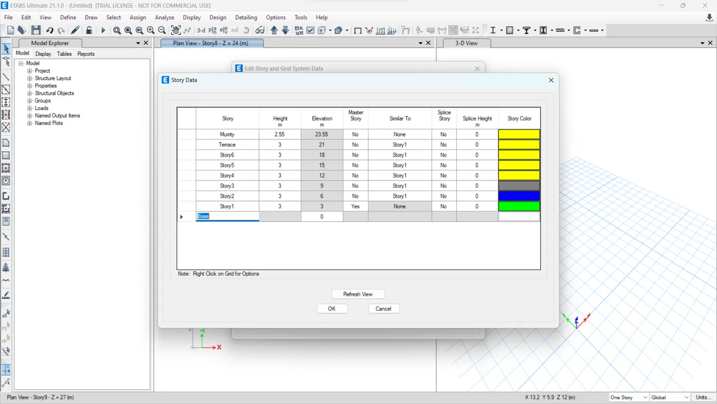
Step 3) Create Grids & add a stories
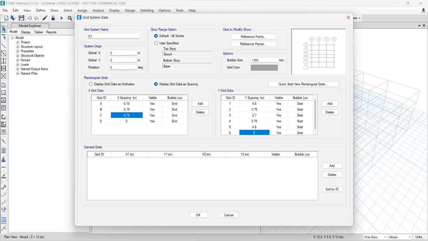
- A new dialog box opened as New Modal Quick Templates
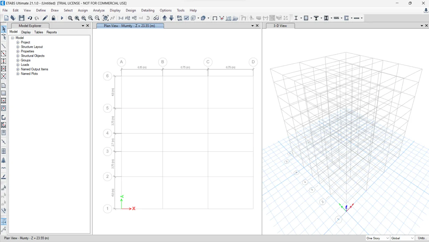
- Select Custom Grid Spacing and click on the Edit Grid Data
- Modify the X & Y Grid Data from the Grid System Data dialog box and click OK
Step 4) Define Material
- The grid arrangement of the new modal will open
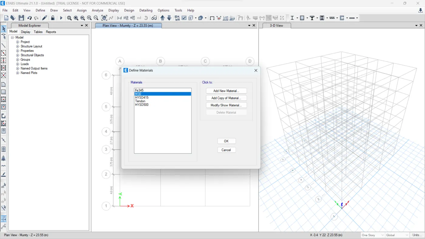
- Go to Define → Material Property
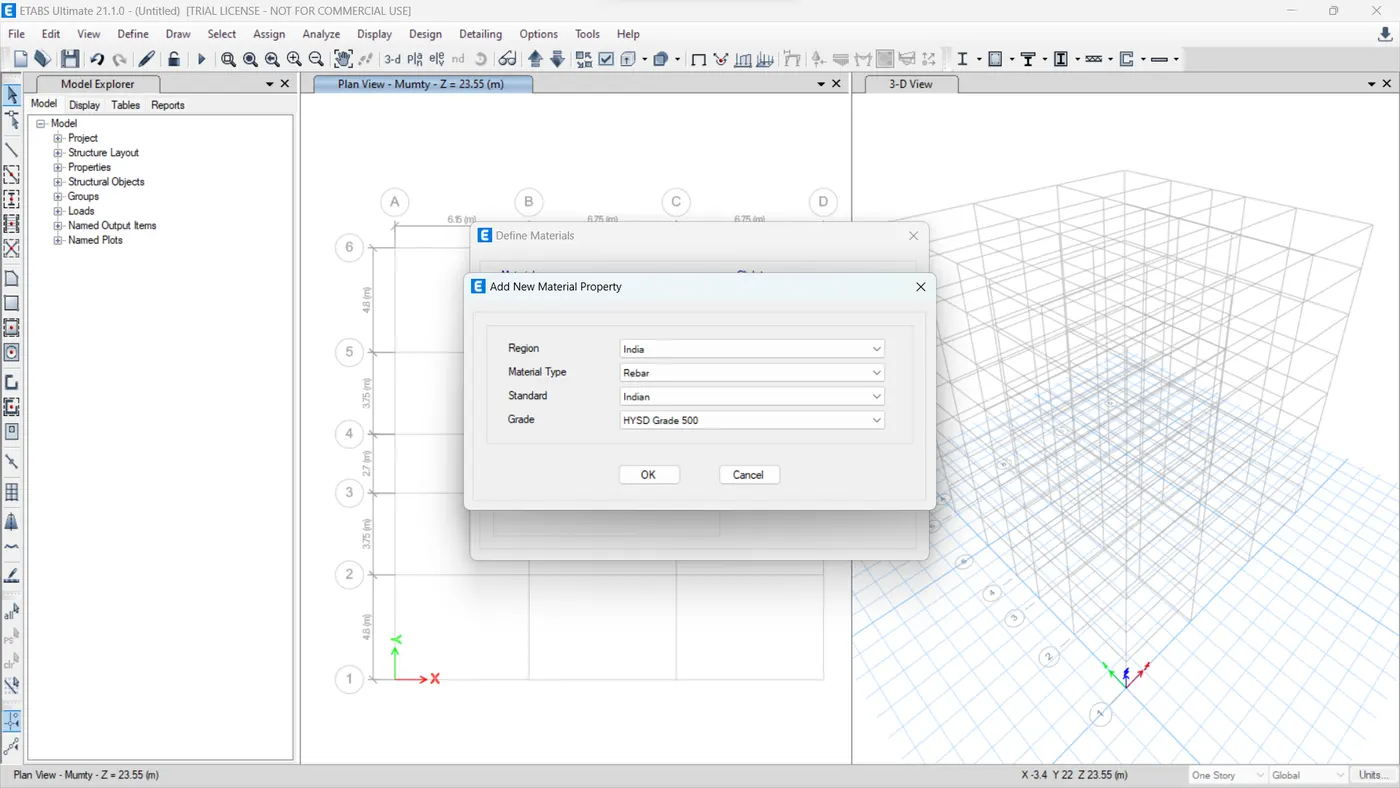
- Define Material → Add New Material
- Add New Material → Material Type Concrete → Grade M30 click OK
- Material Properly Data dialog box will open, click OK
- Again, click on Add New Material
- Add New Material dialog box will open, select Material Type Rebar and select Grade HYSD 550 & 415 click OK
- Material Properly Data dialog box will open, click OK
Step 5) Add Column, Beam & Shear Wall
- Go to Define → Frame Section → Section Property
- Click on Add New Property from Frame Properties dialog box
- Click on Rectangular Section for Beam from Frame Property Shape Type
- Change the Property Name as B300X450 and Material M30 and section dimension Depth as 450 & width as 300 from Frame Section Property Data, click on Modify/Show Rebar under Reinforcement
- Change Design Type and Rebar Material, click OK
- Again, Add New Property for Column and select Rectangular Section
- Change the Property Name, Material and Dimension and Modify/Show Rebar similarly
Step 6) Add Slab
- Go to Define → Slab Section → Section Property
- Click on Add New Property for Slab
- Change the Property Name, Slab Material, Modeling Type and Thikness of Slab
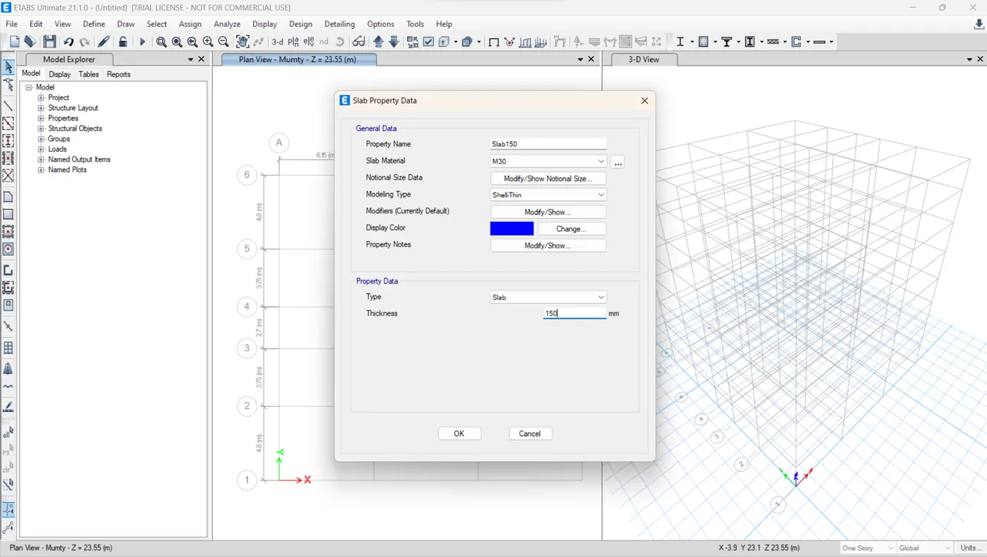
Step 7) Load Pattern
- Go to Define → Load Patterns
- Add Wall & Floor Fininsh Load as Super Dead type
- Simalry add EQX & EQY Load as Seismic type and select IS-1893:2016
- Modify the lateral load and uncheck the other direction except X for EQX and Y for EQY
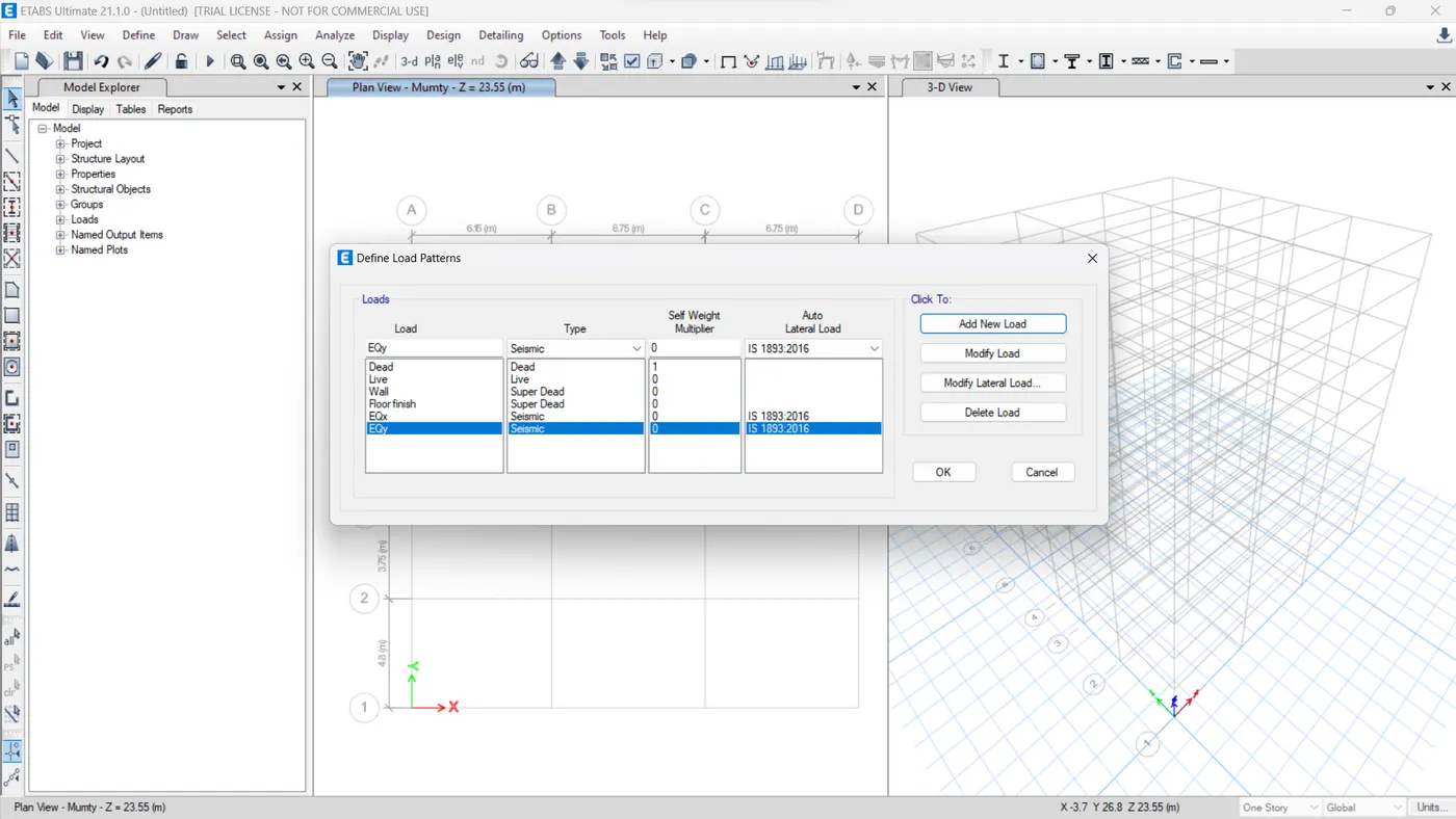
Step 8) Define Mass Source
- In Define → Select Mass Source
- Click on Modify/Show Mass Source
- Check mark only Specified Load Pattern
- Add wall, live and dead load
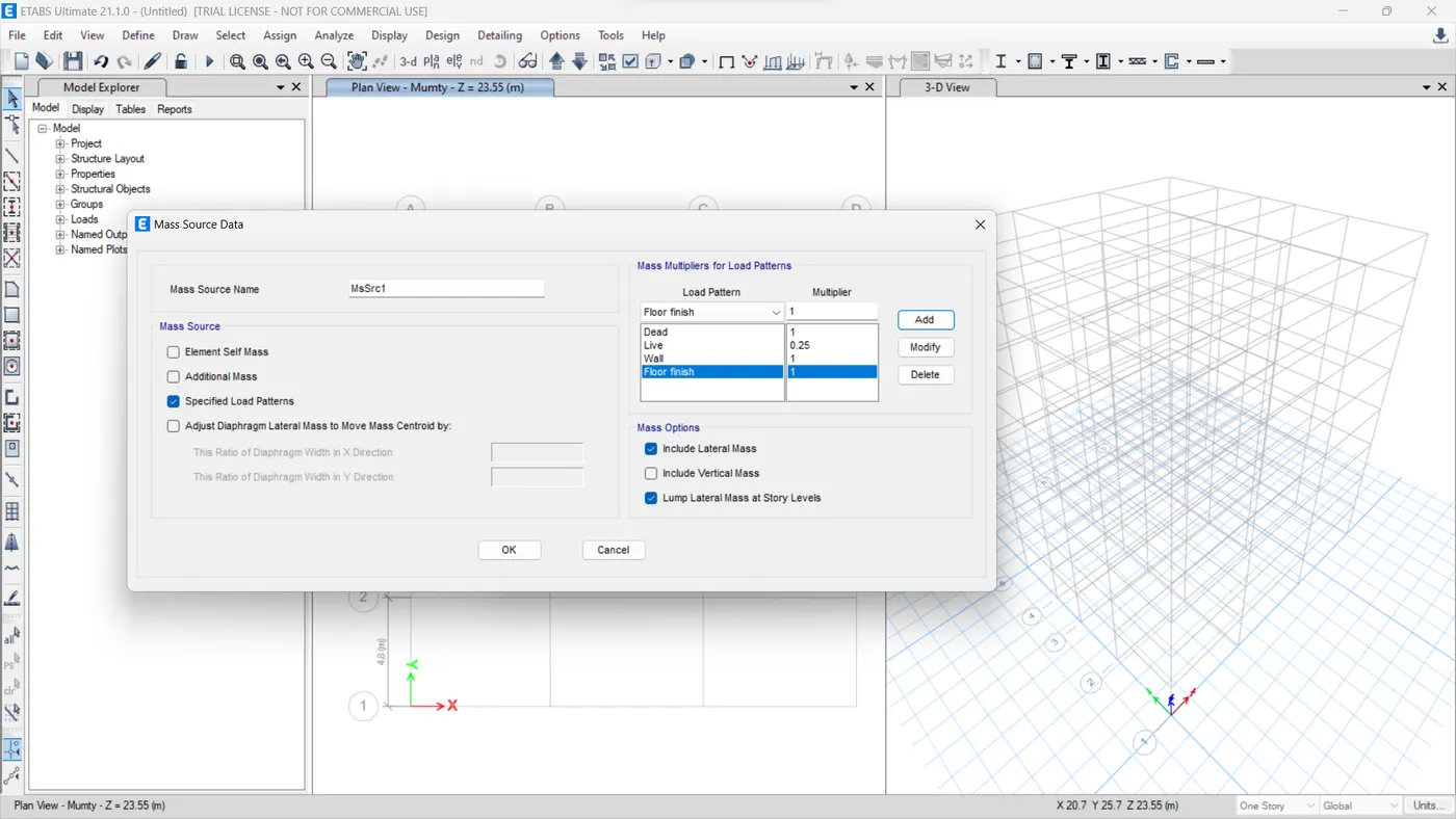
Step 9) Response Spectrum
- Go to Define → Functions
- Open response spectrum
- Modify the spectrum details
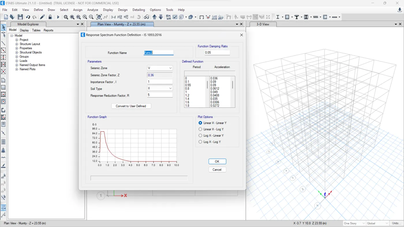
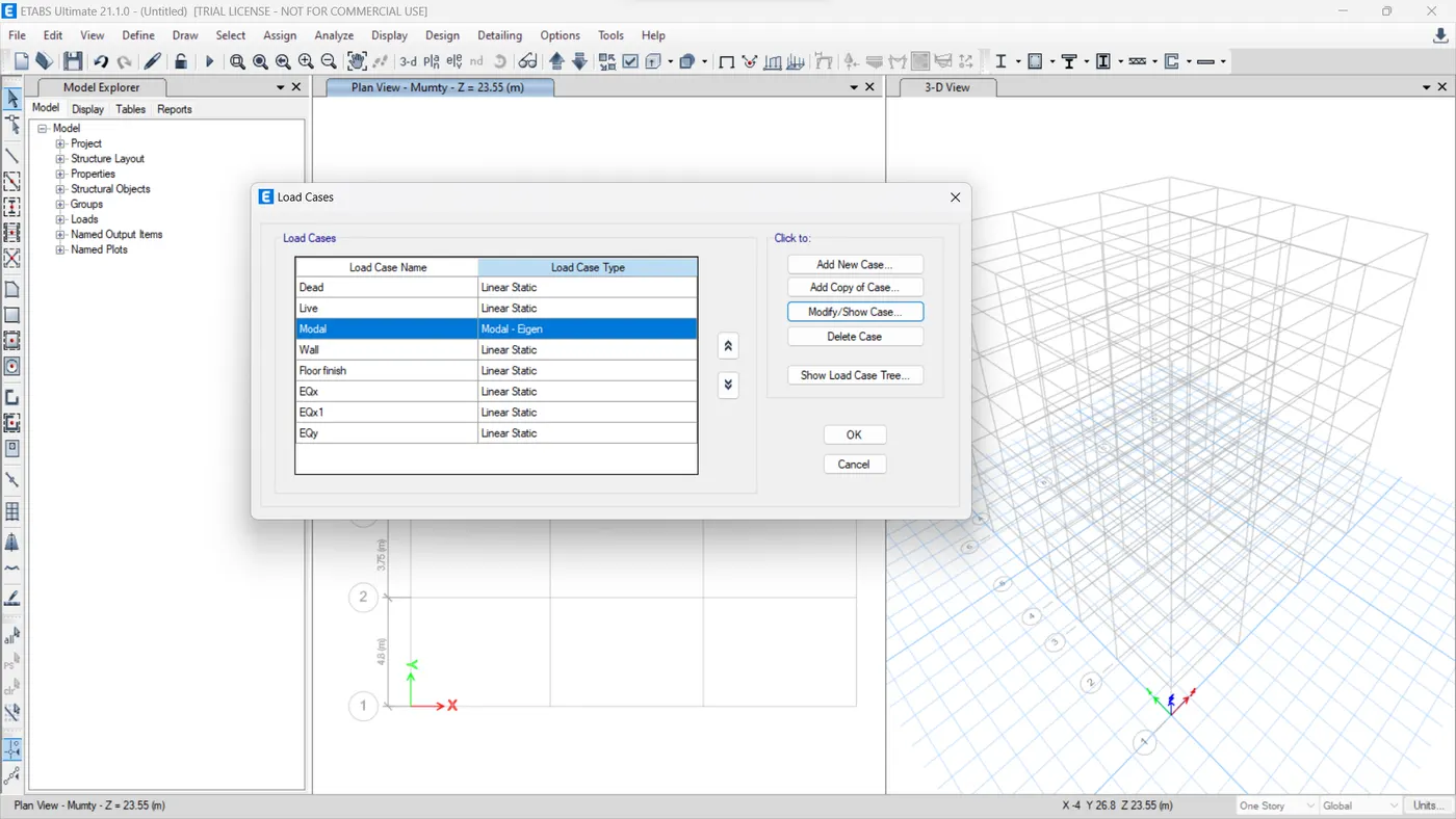
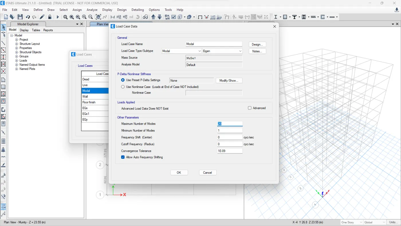
Step 10) Check Load Case
- Go to Define → Load Cases
- Check load cases and click OK
- Modify the model
Step 11) Load Combinations
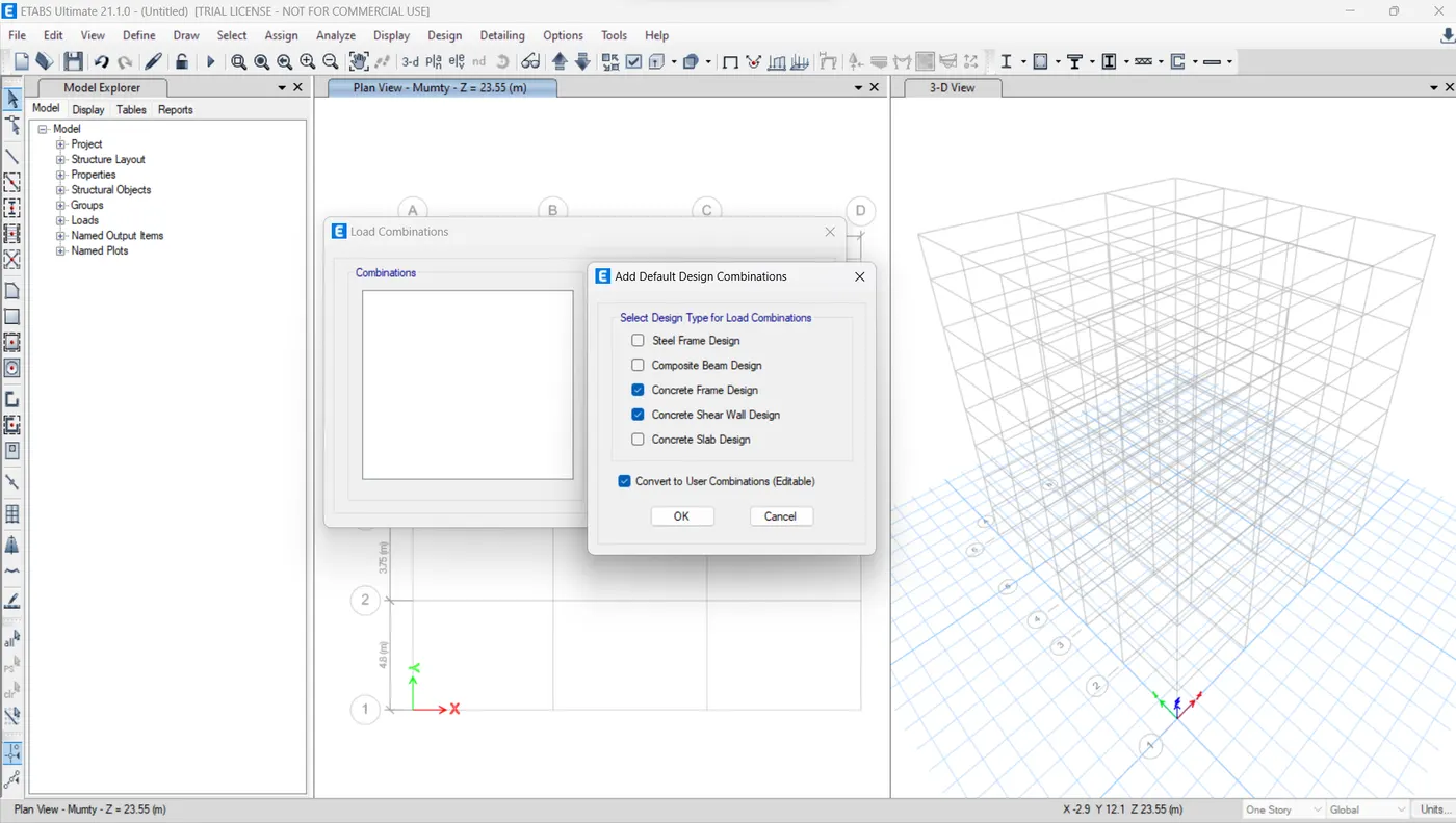
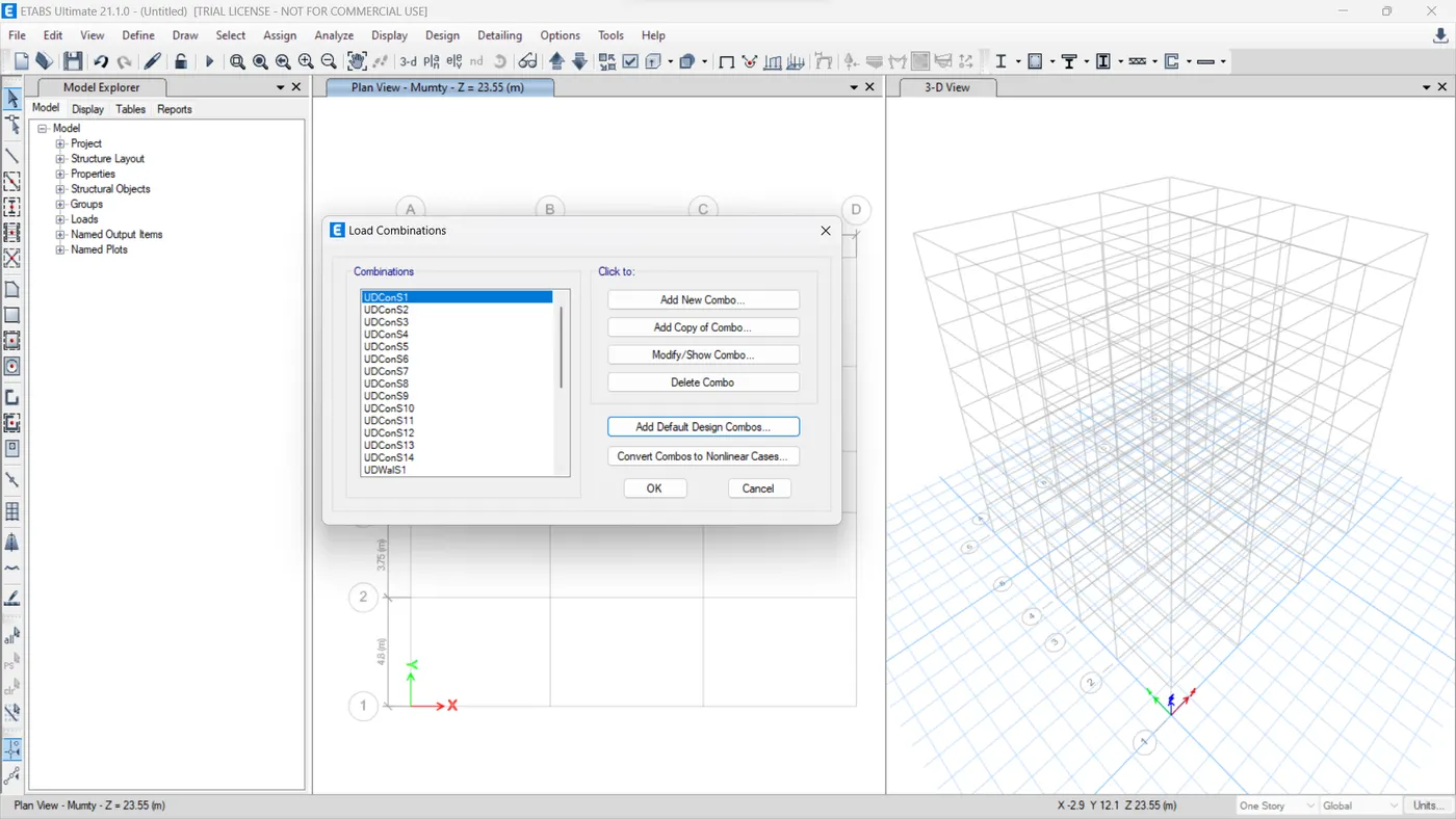
- Go to Define → Load Combinations
- Add Default Design Combination
- Check on Concrete Frame Design,Concrete shear wall Design and Convert To User Combination
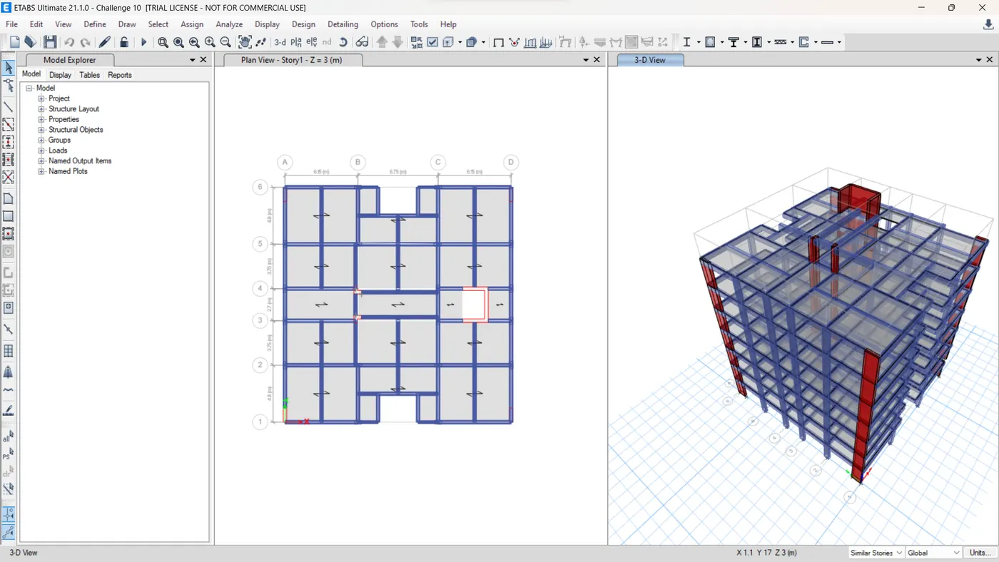
Step 12) Draw Column and Shear wall
- Select Quick Draw Column
- And change the Properties
Step 13) Assign Load
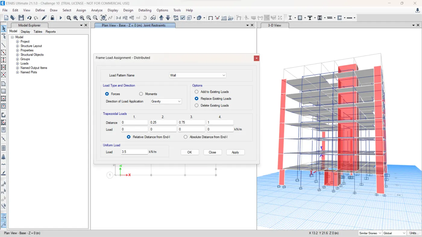
- Select all Beam
- Assign Frame Load as a Distributed
- Load Pattern Name Wall → Uniform Load 3.5kn/m
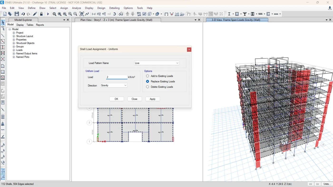
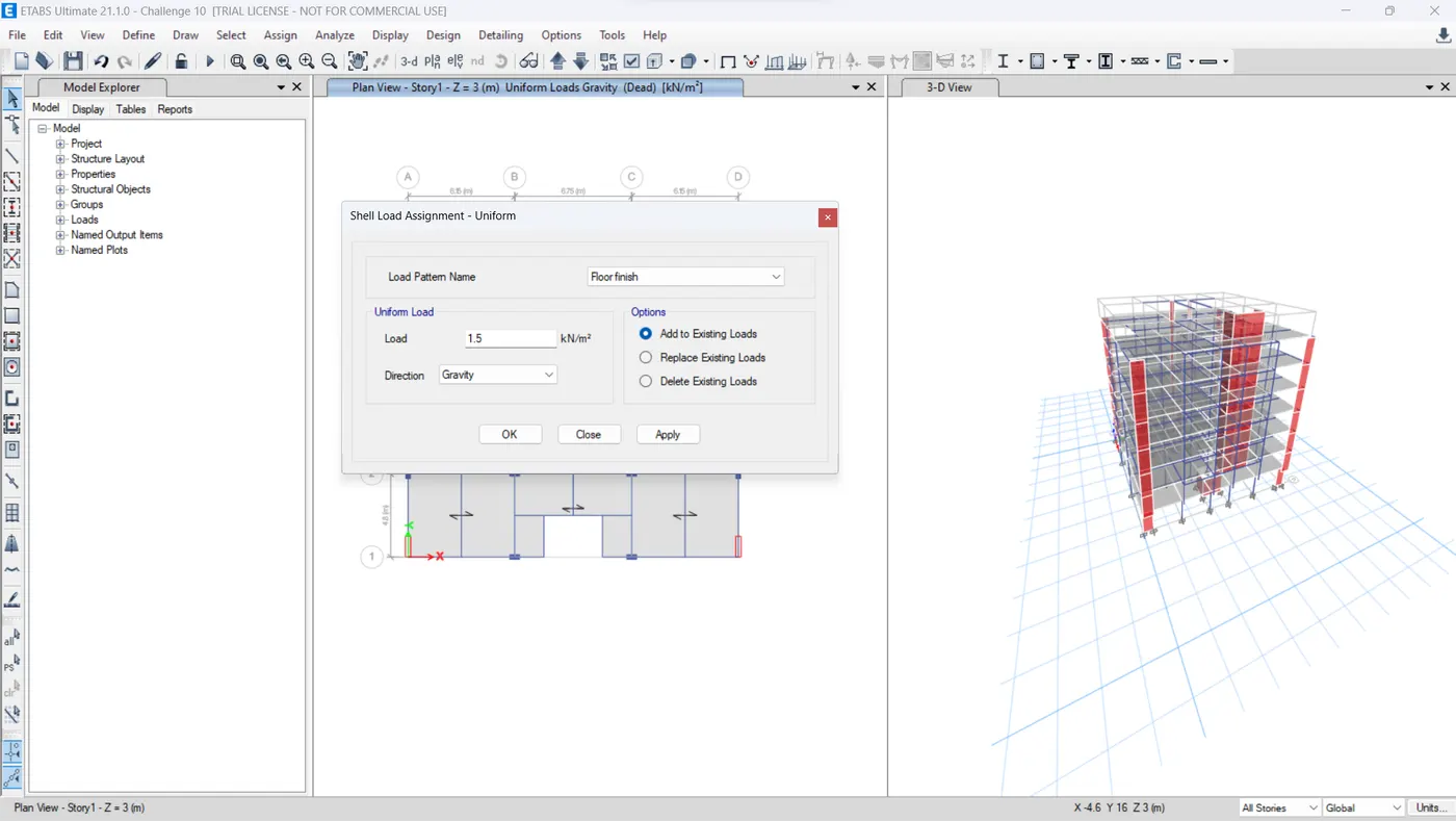
- Similarly select slab
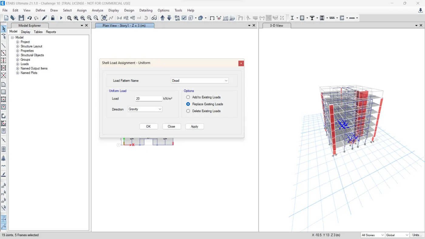
- Assign shell load as uniform
- Load Pattern Name live → Uniform Load 2 kn/m
- Added floor finish and water tank load
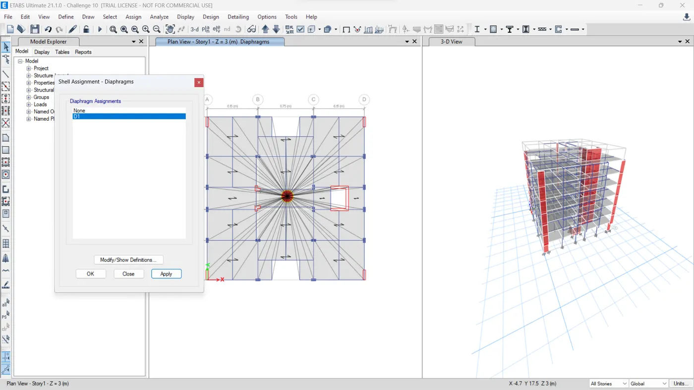
Step 14) Add Diaphragms
- Select Slab
- Assign Shell as Diaphragms
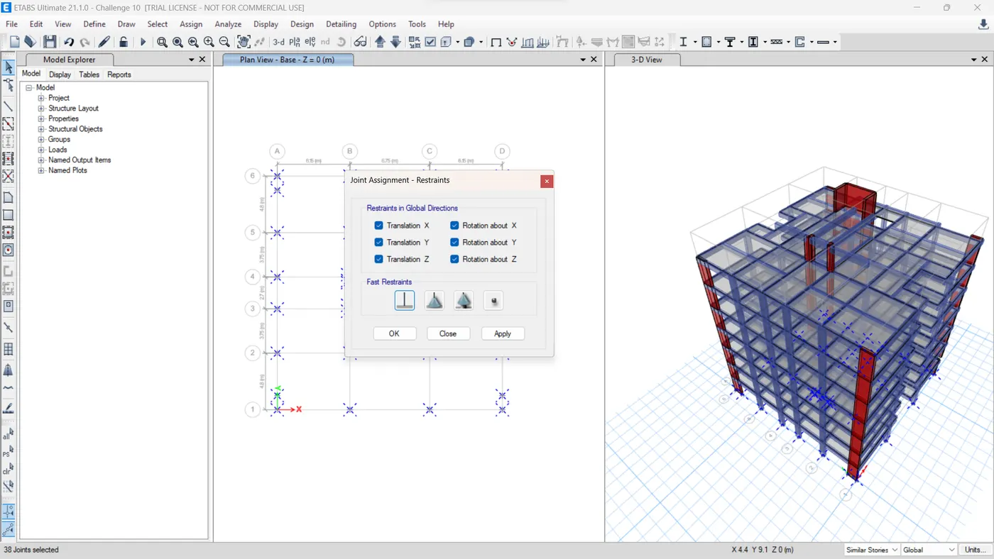
Step 15) Base Support
- Goto the base plan
- Select all the joitns
- Assign → joints → restrian
- Select fast restrain and click ok
- All the joints are fixed
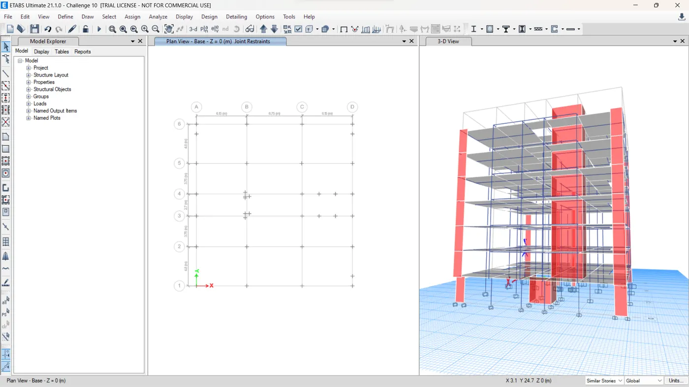
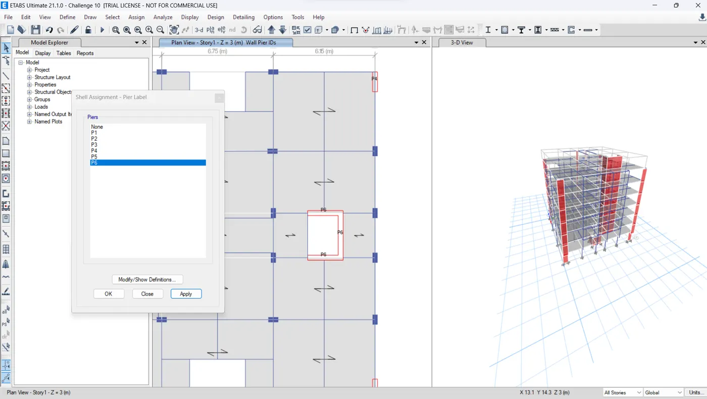
Step 16) Assign Peir Lebal & live load reduction
- From define added pier labels
- Assign one by one on shear wall
- Add live load Reduction factor on each floor
Step 17) Check Modal and Run The Analysis
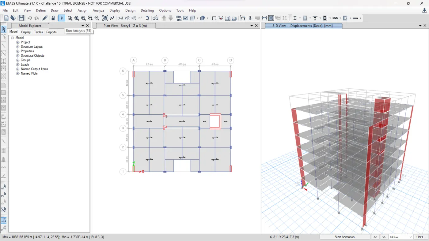
- Here I got no warning so that modal ok, we can run analysis
- After completion of anaysis we got max. & min. deflection
Step 18) Check Result
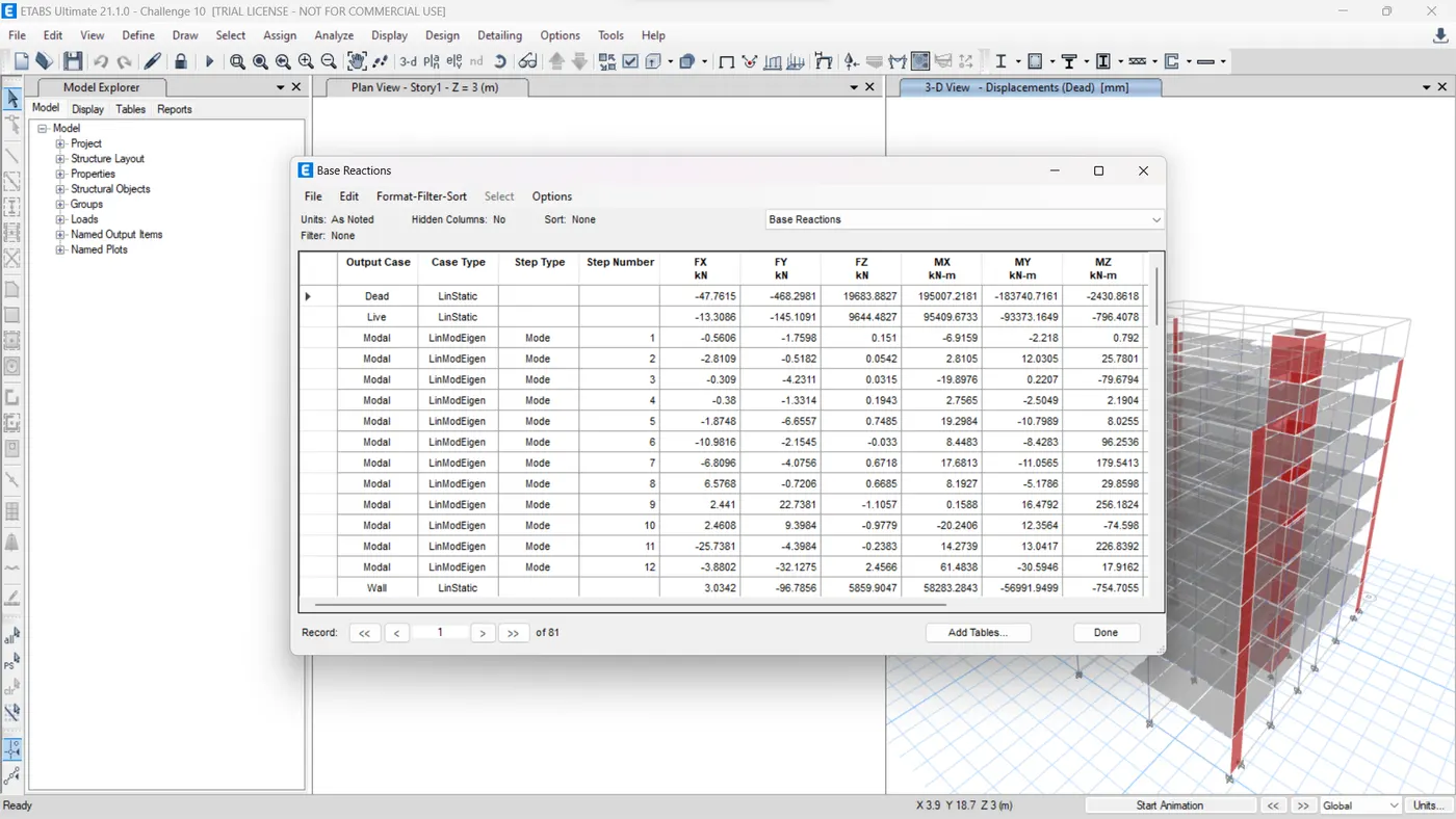
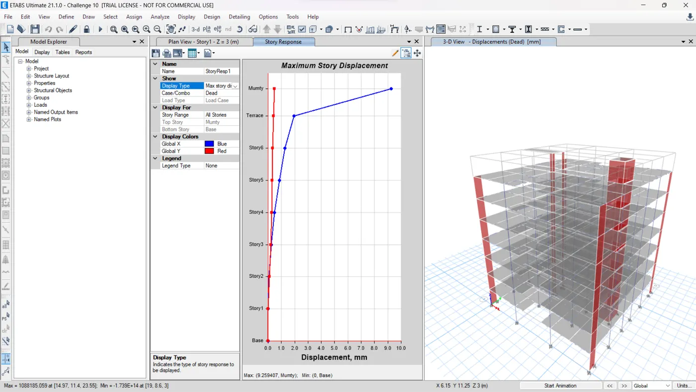
- Form table checked the modal infromation and compare the result
- First two fundamental modal mass grater than the torsional mode
- Modal mass participation for first 3 modes dominates at least 65% (Achieved for X-axis only)
- Mode-1 and Mode-2 differs by 10% (Achieved)
- Principal modes be greater than Torsional mode (Achieved)
- Inter story drift ratio limited to 0.004 (Achieved)
Result:
To model and analyse the apartment with all seismic consideration, based on given architectural input and to check the seismic performance of an apartment using ETABS and attach the model.