Structural Modelling using Etabs 2018
- AIM : To model and analyse G+9 storey building using ETABS with application of proper load cases and load combinations for the given typical floor plan drawing.
PROCEDURE : - Initially open the given architectural plan in Auto CAD and study the plan and locate the positions of beams , columns and shear walls.
- After done the positioning then the structural plan should implemented in the ETABS software.
- Open the ETABS software and click on new model option.
- Then select use built-in settings with option and fill the units and codes as per the details we used.
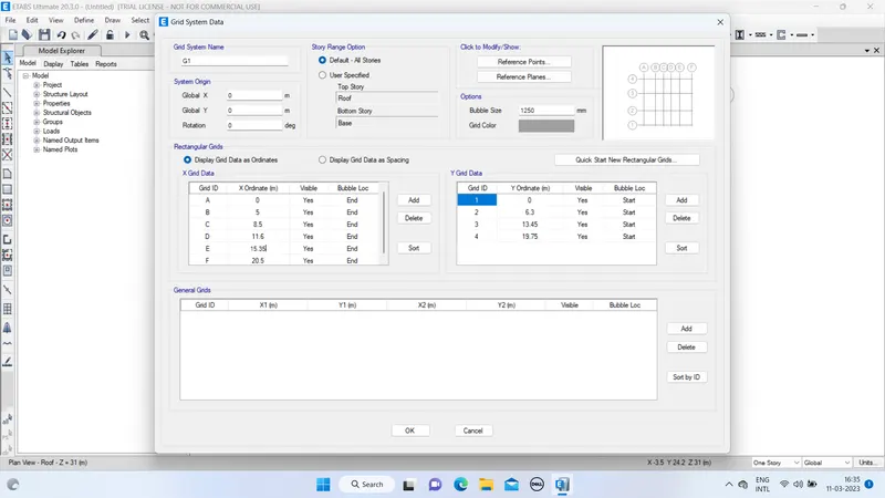
- Then select the grids and storeys and respectively it dimensions also.
- Provide 4 grids at X-direction and 6 grids at Y-direction with proper spacing.
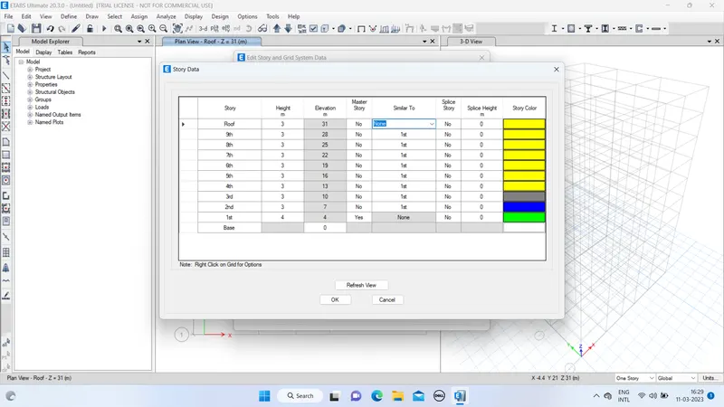
- Now define each storey and storey height.
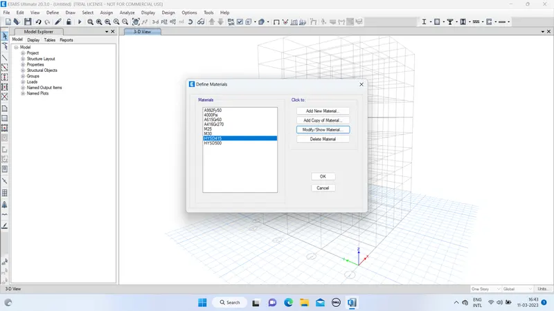
- Click on define tab and select materials. Choose material type such as concrete for M25/M30.
- Similarly for rebar material,select grade as HYSD500/HYSD415.
- Click Define tab and select frame section property.
Provide beam dimensions as 250x450.Then modify the rebar details. - Provide column dimensions as 400x400 and then modify the rebar details.
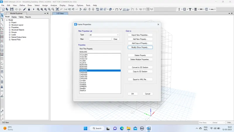
- Click on Define and select section properties. Click on slab section
Provide the thickness of the frame as 150mm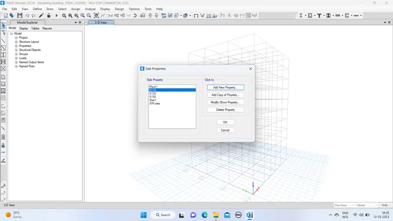
- Click on Define and select section properties and click on Wall sections.
Set the thickness of the wall as 300mm.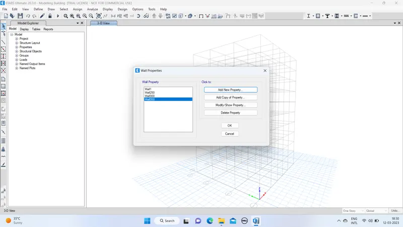
- By using Quick draw column/beam option place the columns in the floor plan at each grid intersection.Select all storey option.
- Similarly draw the beams as per the floor plan.
- To draw the sub beams,use replicate options.
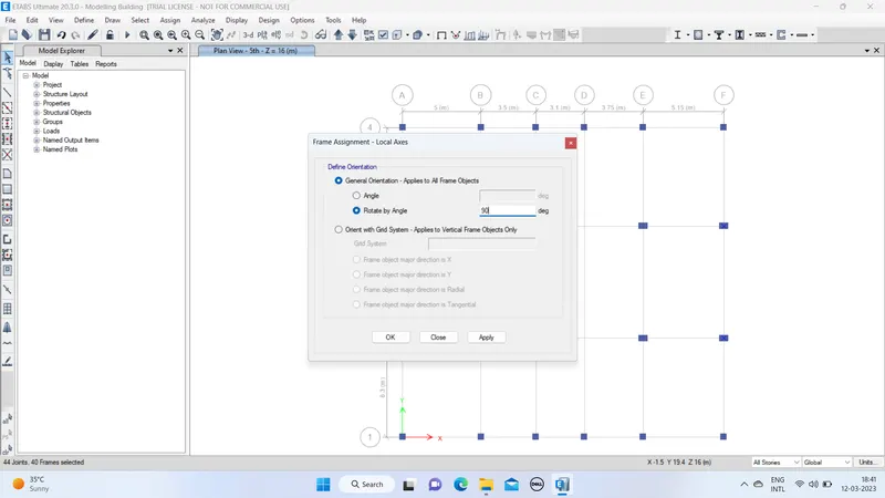
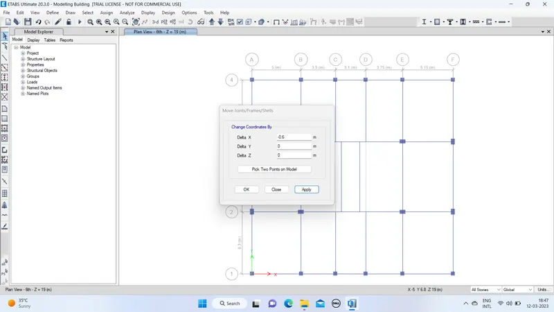
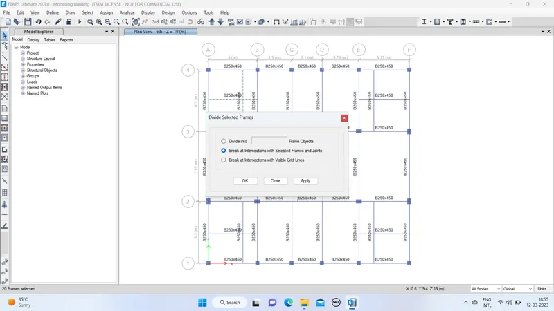
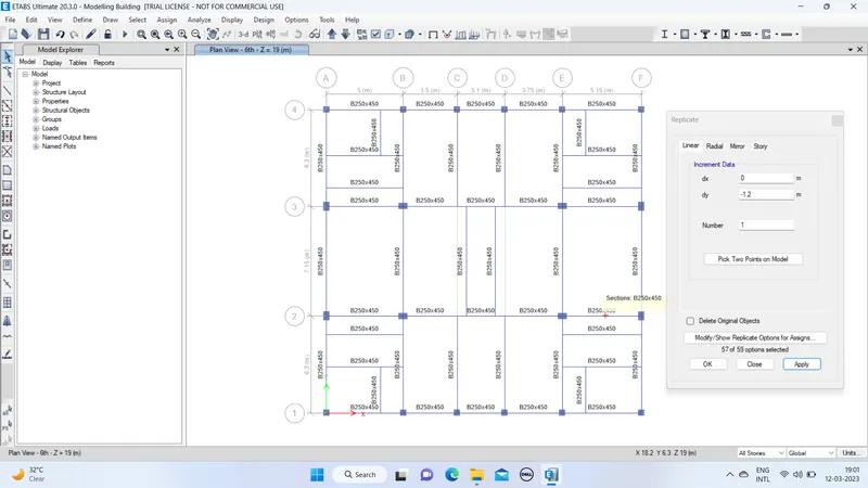
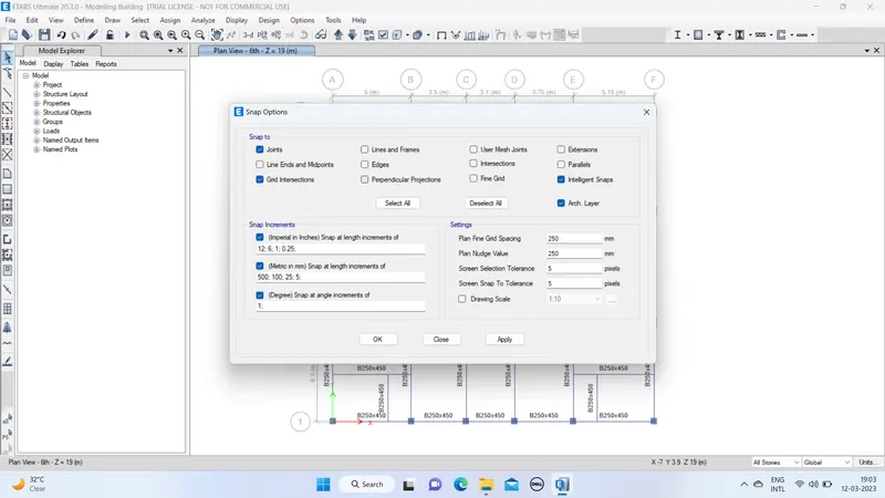
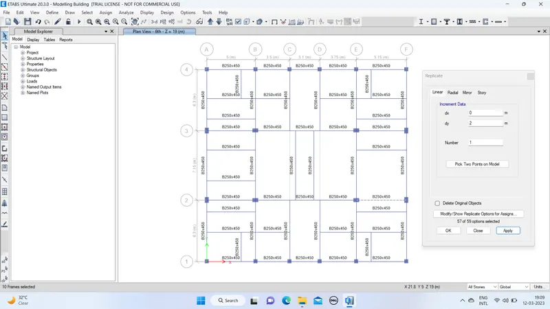
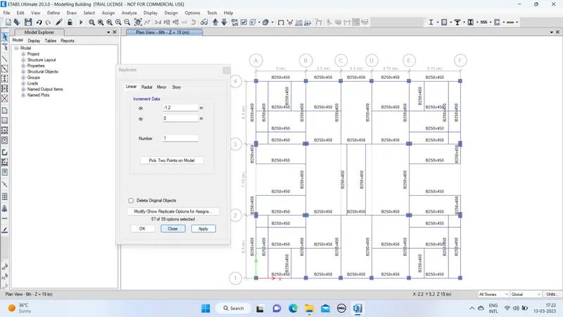
- Draw the shear walls in required places.
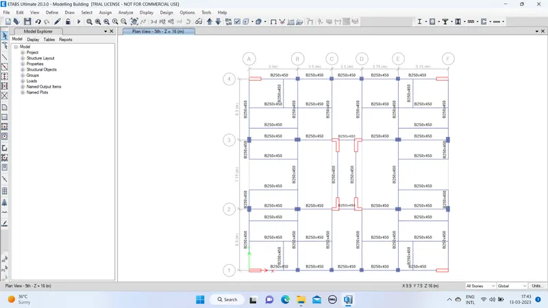
- By using Quick draw floor/draw rectangular floor plan option place the floors.
select all storey option in bottom tool bar.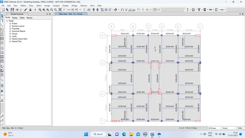
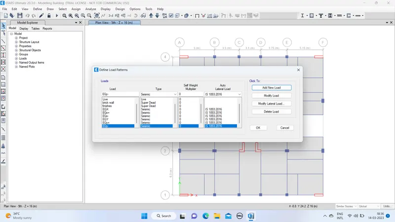
- Click on the load patterns and define loads as per requirememt.
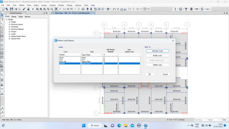
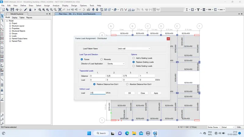
- Apply brick wall load in all the beam component.
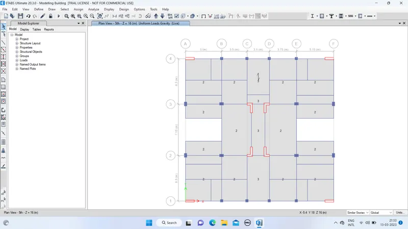
- Apply live load as per IS 875.
Live load = 2KN/sq.m (As per table no.1 from IS 875 part 2)
Live load = 3KN/sq.m for balconies,lift area and walk-way (As per table no.1 from IS 875 part 2)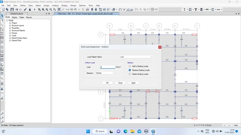
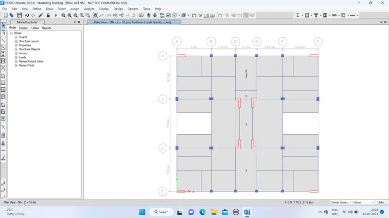
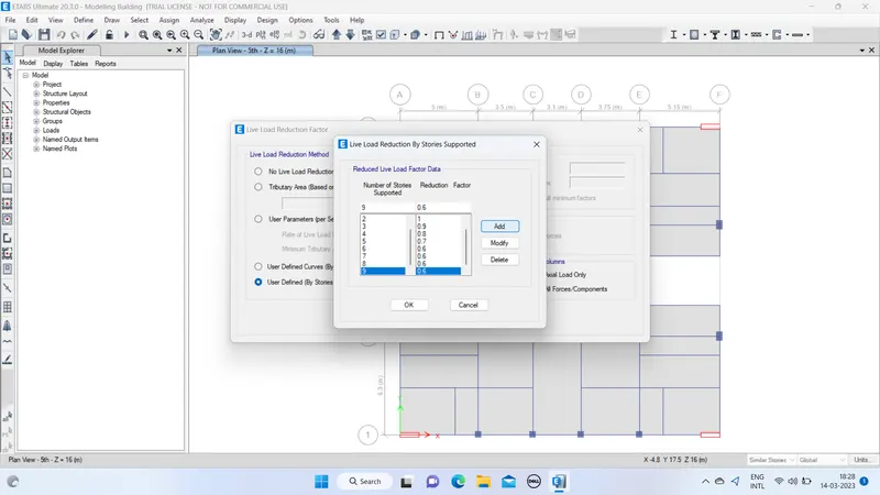
- Similarly the reduction factor has been taken from clause 3.2.1 in IS 875 part 2
- Click on the load patterns and define the seismic loads.
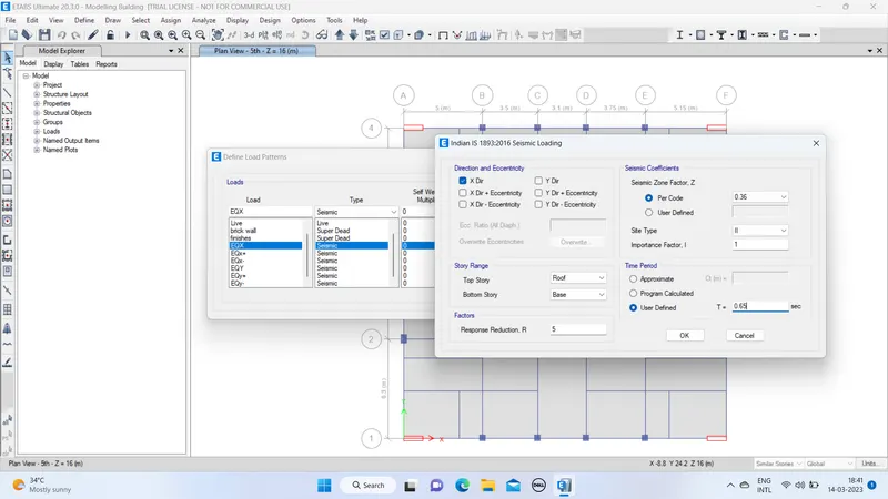
- Calculate the time period T value frm IS 13920 clause no.7.6.2
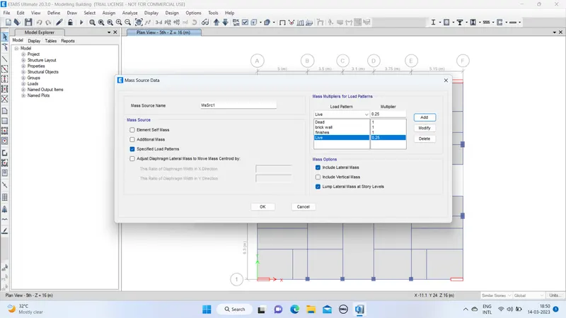
- Define mass source
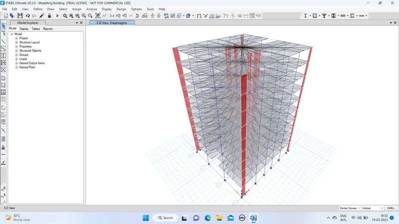
- Assign diaphragms to all the floors.
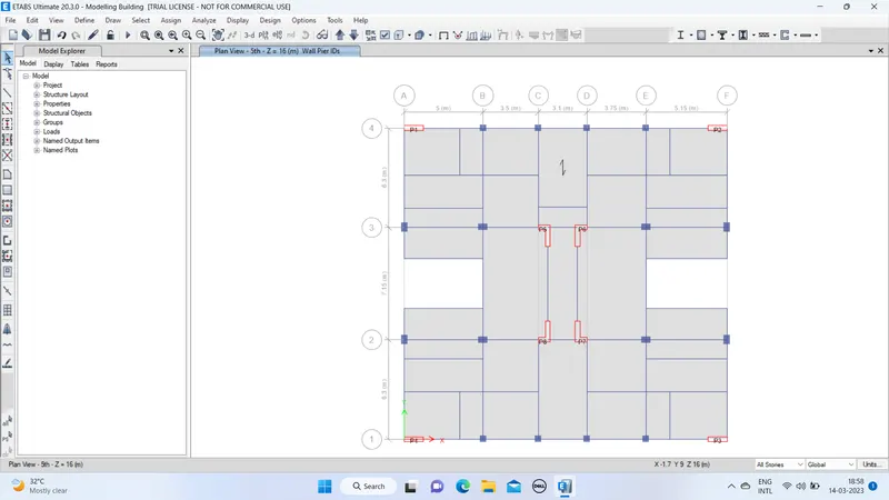
- Go to define.click on pier lables and add the pier names for the shear walls.
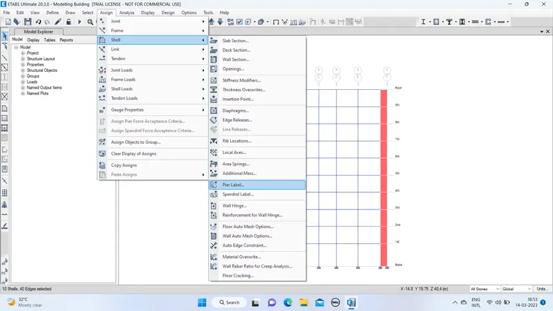
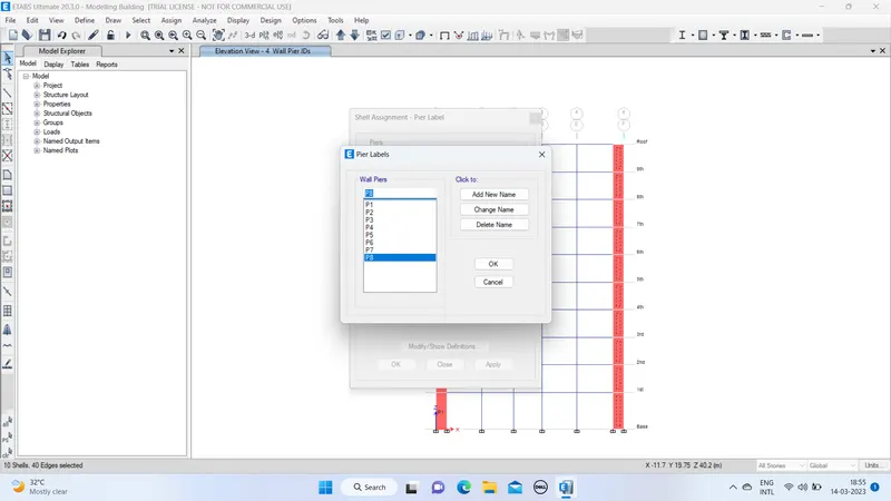
- Select the shear walls one by one and assign the pier labels.
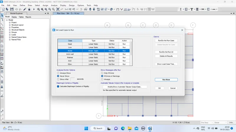
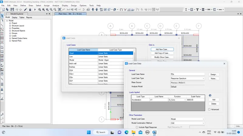
- Click on the analyse , then click on the load cases to run.Tick mark the calculate diaphragms centres of rigidity.
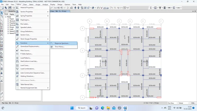
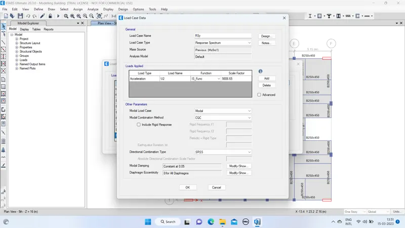
- Click on define , select function and select on Response spectrum.
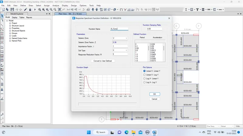
- Define the response spectrum in both X and Y direction.
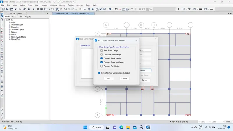
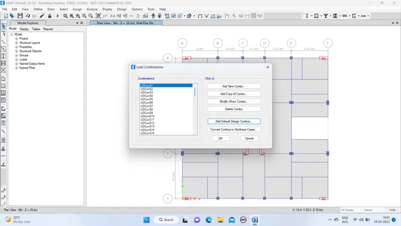
- Select load combinations , click on the default design combinations.
RESULT :
MODAL PARTICIPATION RATIO CHECK - After the completion of analysis,then go to the display - show tables - analysis results - structural output - modal information - modal mass participating ratio.
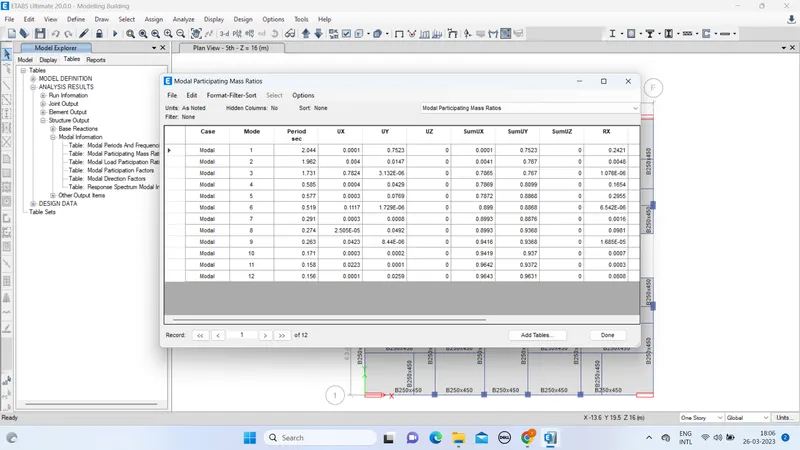
- Hence satisfied the modal participation of translational mode - first two fundamental modes should be greater than the transional mode(third one).
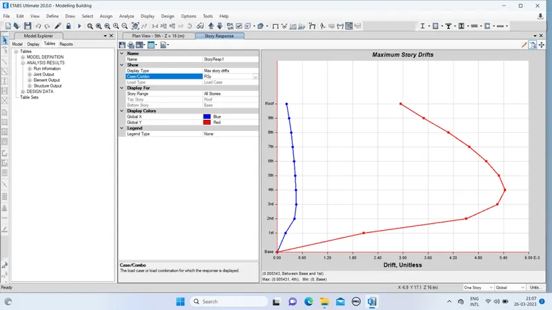
CHECK FOR INTER-STOREY DRIFT : - In X direction
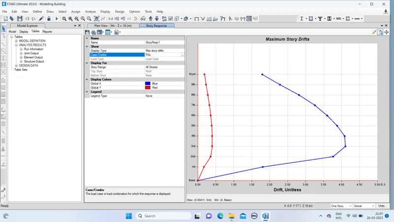
- in y direction