Structural analysis of a buidling using Robot Structural Analysis
1) What are HVAC systems? Why are they essential in the modeling of buildings
The initials HVAC stand for Heating, Ventilation and Air Conditioning. Primary HVAC equipment includes heating equipment, ventilation equipment, and cooling or air-conditioning equipment. Central HVAC systems locate away from buildings in a central equipment room and deliver the conditioned air by a delivery ductwork system.
I. Air filter
II. Supply fan
III. Exhaust or relief fans and an air outlet
IV. Outdoor air intake
V. Ducts
VI. Terminal devices
VII. Return air system
VIII. Heating and cooling coils
IX. Self-contained heating or cooling unit
X. Cooling tower
XI. Boiler
XII. Control
XIII. Water chiller
By these systems they will be essential for providing the central air conditioning to the building.
2) From week 7 assignment, based on the building designed use the same Revit file to design a HVAC system for each floor to cover the topics included in the class.
a. Typical HVAC unit includes Distribution center
b. Collector
c. Ducts
d. Blower
Based on the layout choose appropriate ducts and elevation using property browser and assign the components to appropriate groups to complete modeling of the HVAC unit
Aim:
design of a HVAC system for each floor to cover the topics included in the class
procedure:
I. Go to file
II. Click on new
III. And select the mechanical templete
IV.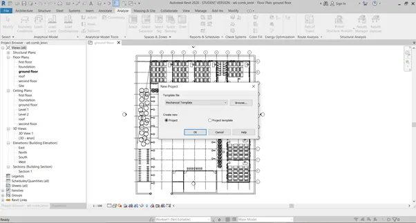
V. Go to menu bar and select the link Revit
VI. Add and Select the required file
VII. And ok
VIII.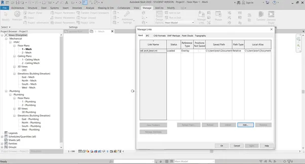
IX. In a menu bar click on systems
X. Select air terminal
XI. And in properties browser drop down select the required equipment
XII. And snap on the plan
XIII.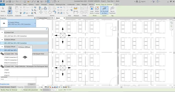
XIV. By select all provide offset to them
XV.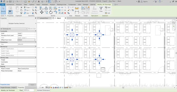
XVI. And also add the supply air similarly
XVII.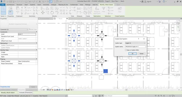
XVIII. Select the supply units and click on duct and next generate layout
XIX.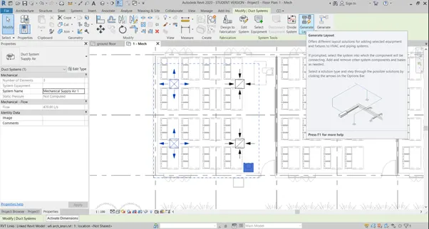
XX. Similarly for the return diffuser
XXI.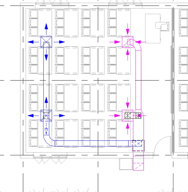
XXII. And provide offset to the duct main
XXIII.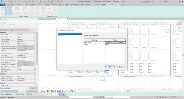
XXIV. Also offset the duct branch
XXV.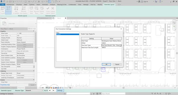
XXVI. Copy this system to all rooms
XXVII.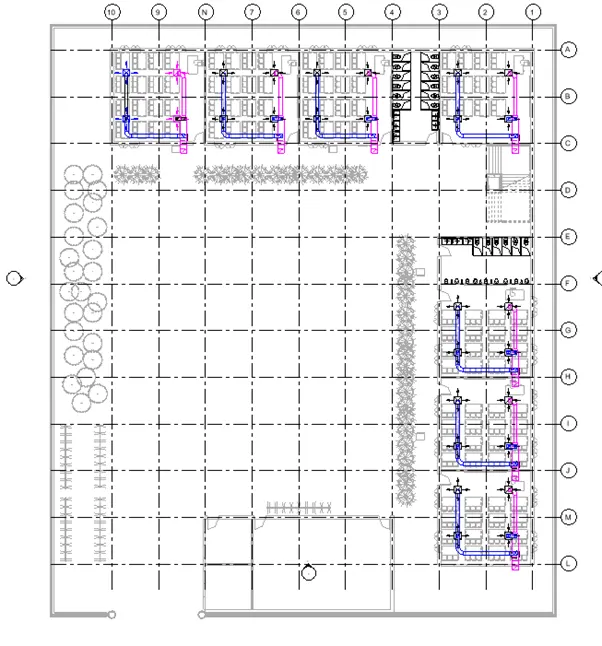
XXVIII. And copy it to the all levels
XXIX.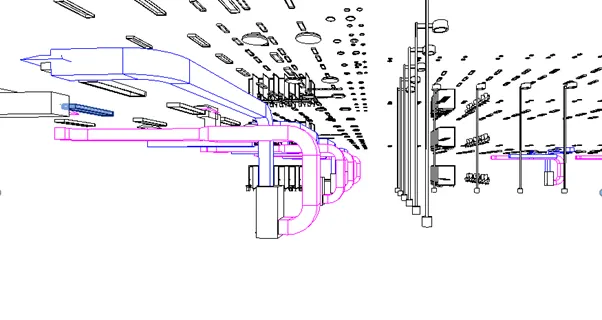
Result:
design of a HVAC system for each floor was done
3) Use the add-ins tab to load plug-ins for robot structural analysis to your Revit software
Aim:
Using the add-ins tab to load plug-ins for robot structural analysis to your Revit software
Procedure:
I. In the Revit software click on the cart symbol
II. The automatically network browser of the Revit extension will be popped up
III. There search for robot structural analysis 2020
IV. And download the extension and install it
V. There by Using the add-ins tab to load plug-ins for robot structural analysis to your Revit software was done
VI.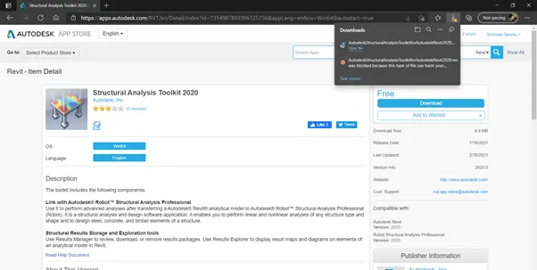
VII.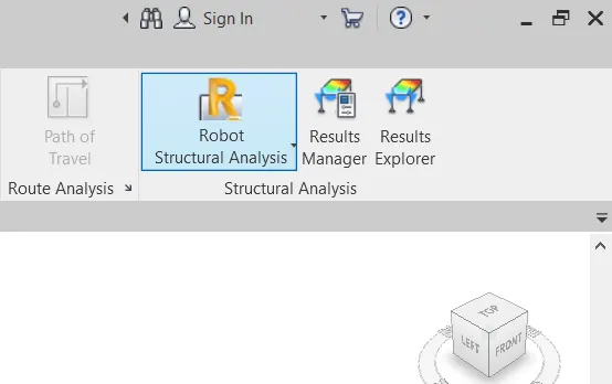
Result:
Using the add-ins tab to load plug-ins for robot structural analysis to your Revit software was done
4) Why do we need to assess buildings/analyze while modeling elements? Does design affect modeling in anyways?
Ans:
Analysing the model is one of the essential components of the design of the model. This provides as weather the building is stable and sustainable were the elements used in the model were enough to sustain the loads can be checked
So, analysing the modelling elements is a essential tool and by this way is the structure goes to the failure and we need to change the dimensions or properties of the structure and it will sustain the building and so design affects the modelling.
5) From the structural model developed in week 6 and 7, export the complete analytical model to robot structural analysis.
a. List your assumptions on what boundary conditions will be realistic for the analysis approach
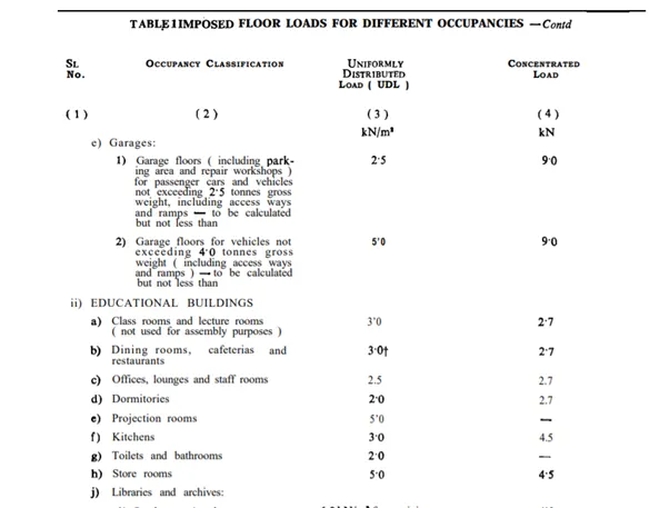
b. Use the design standards to decide what loads must be applied to floorings based on the type of structure decided
c. List the load combinations and include them in the analysis model
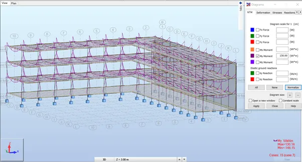
d. Analyze the building and report the following results
i. Maximum Moment in each floor for all Load Combinations
ii. Maximum Displacement in each floor for all Load combinations
iii. Lateral Displacement in building for all Lateral Load combinations
e. After analysis, do you think you have a better approach or idea in modeling structural members?
Aim:
Perform the robot structural analysis on the analytical model.
Procedure:
• All footings are assumed as the fixed
• Live load of 3kn/m2 as the area/floor load as per IS875 part2.
•
List of load combination
a. Case 1: 1.5 DL + 1.5 IL
b. Case 2: 1.2 DL + 1.2 IL + 1.2 EL/WL
c. Case 3: 1.2DL + 1.2 IL - 1.2 EL/WL
d. Case 4: 1.5 DL + 1.5 EL/WL
e. Case 5: 1.5 DL - 1.5 EL/Wl
f. Case 6: 0.9 DL + 1.5 EL/WL
g. Case 7: 0.9 DL - 1.5 EL /WL
h. Load combinations for limit state of serviceability (short term effects) as per IS 456: 2000:
i. Case 1: 1 DL + 1 IL
j. Case 2: 1 DL + 0.8 IL + 0.8 EL/WL
k. Case 3: 1 DL + 0.8 IL - 0.8 ELWL
l. Case 4: 1 DL + 1 EL/WL
m. Case 5: 1 DL + 1 EL/WL
n. Load combination as per IS 1893:
o. As per IS 1893 while doing seismic design only earthquake load shall be considered. So wind load is neglected in the combination of earthquake load.
p. Load combination for limit state of collapse:
q. Case 1: 1.5 DL + 1.5 IL
r. Case 2: 1.5 DL + 1.5 ELx
s. Case 3: 1.5 DL - 1.5 ELx
t. Case 4: 1.5 DL + 1.5 ELy
u. Case 5: 1.5 DL - 1.5 ELy
v. Case 6: 1.2 DL + 1.2 IL + 1.2 ELx
w. Case 7: 1.2 DL + 1.2 IL - 1.2 ELx
x. Case 8: 1.2 DL + 1.2 IL + 1.2 ELy
y. Case 9: 1.2 DL + 1.2 IL - 1.2 ELy
z. For overturning the following load combinations should be considered:
aa. 0.9 Dl + 1.5 ELx
bb. 0.9 DL - 1.5 ELx
cc. 0.9 DL + 1.5 ELy
dd. 0.9 DL - 1.5 Ely
II. Only top 7 load combinations were assumed in this project
III. Go to open
IV. And oprn the w6 struc file
V. In the menu bar
VI. Go to manage command bar
VII. And select the structural settings
VIII.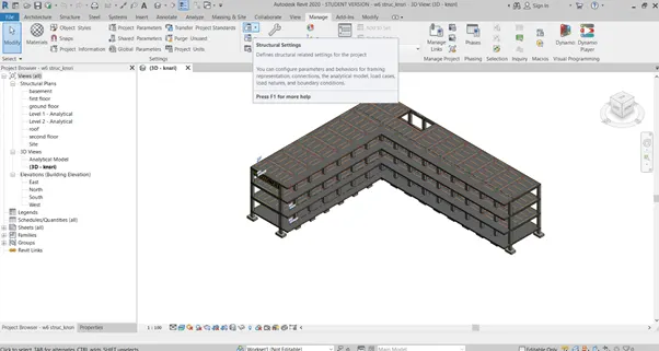
IX. Add all the load combinations in the popup
X.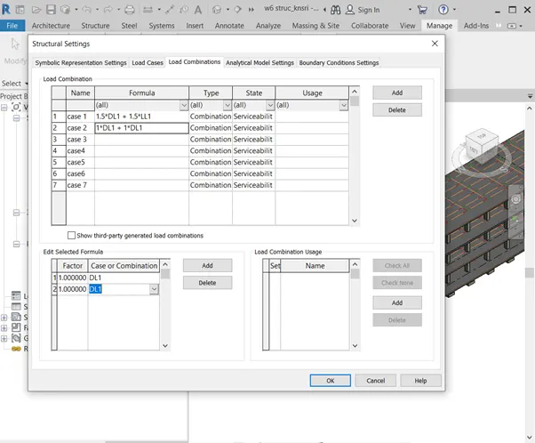
XI. First click on the load combination tab and then select the edit selected formula for loading the load and factor for the load combination
XII.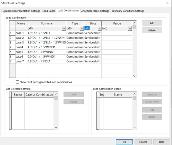
XIII. In menu bar click on analyse and select the boundary conditions
XIV. In bottom drop down select the fixed option
XV. And snap on all the required columns
XVI.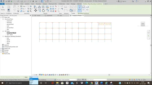
XVII.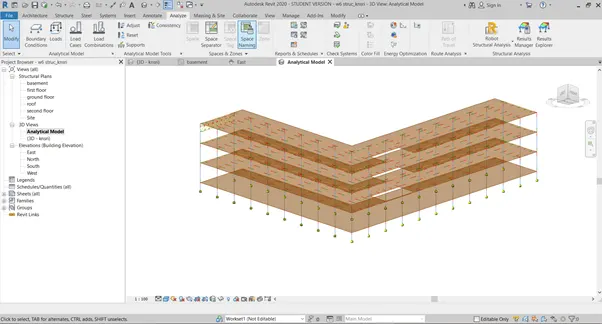
XVIII. Next select the load and select area load
XIX. And pick line command and select edges of the floor and select the boundary of the area load
XX.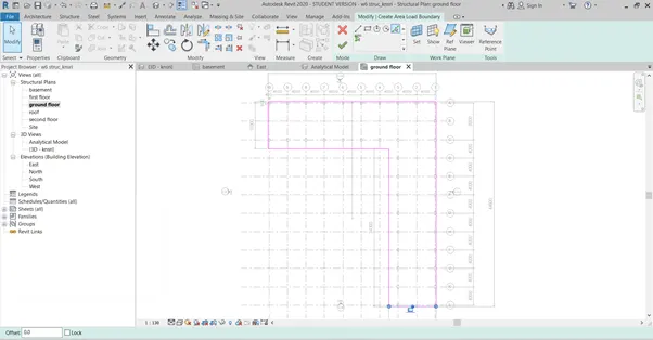
XXI. In properties tab assign the value and type of the load
XXII.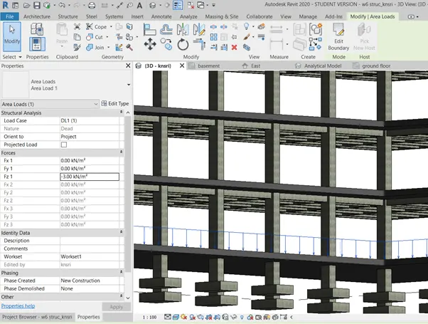
XXIII. Select the load and copy to clipboard and paste to aligned levels
XXIV.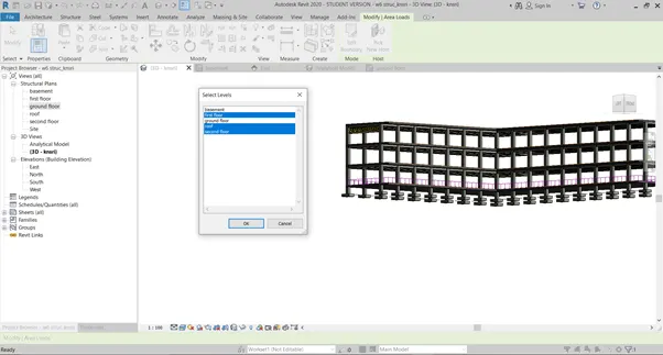
XXV.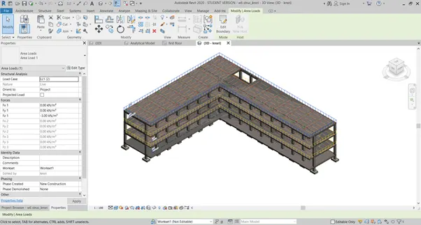
XXVI. Wind load: As per is876 part 4= 39*1.06*1.07*1*1
=41.34m/s
=0.049kn/m2
XXVII. Draw the section of the east face
XXVIII. Go to the section view and select the area load and pick grid 1 as the working plane
XXIX. Similarly select the area load and draw rectangle and create the load
XXX. In properties tab assign the value and type of the load
XXXI.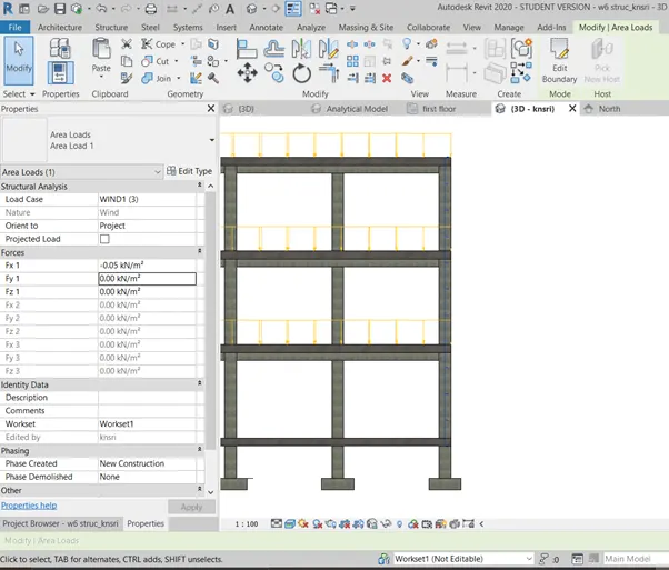
XXXII. In the menu bar select the analyse command
XXXIII. And select the robot structural analysis
XXXIV. And in popup select send model and direct iteration
XXXV. And ok
XXXVI.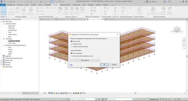
XXXVII. In robot structural analysis click on analysis and calculations
XXXVIII.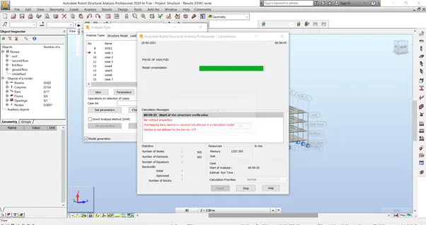
XXXIX. Correct the errors and again perform the analysis
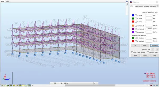
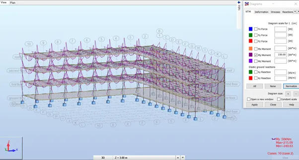
XL. Go to results and select the diagrams in maps
XLI. And in the diagrams tab select the required parameters
Result:
i. Maximum Moment in each floor for all Load Combinations
case1:
Case2:
Case 3:
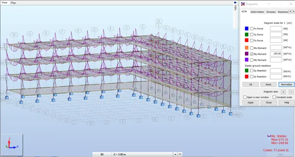
Case 4:
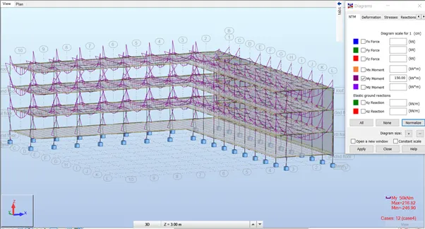
Case 5:
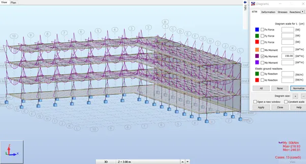
Case6:
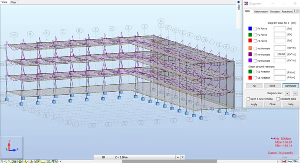
Case 7:
ii. Maximum Displacement in each floor for all Load combinations
case1:
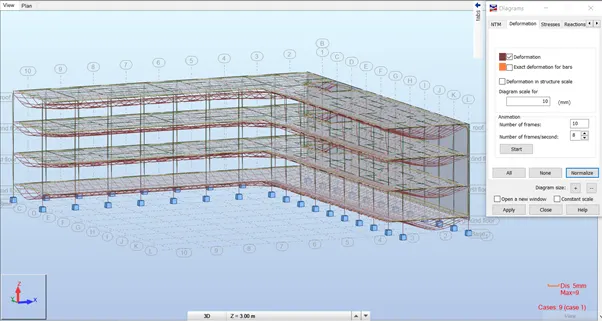
Case2:
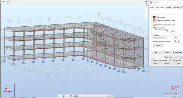
Case 3:
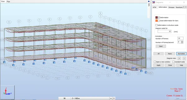
Case 4:
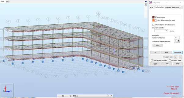
Case 5:
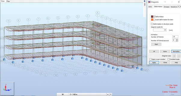
Case6:
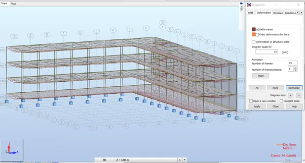
Case 7:
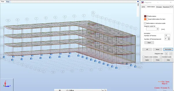
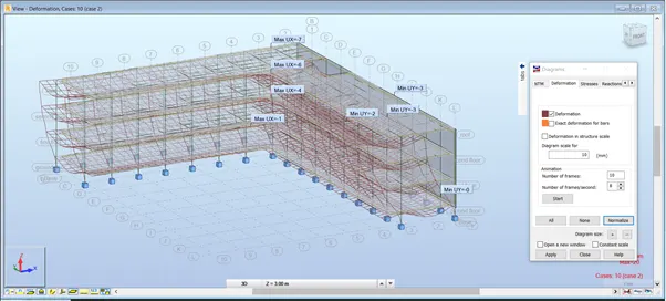
iii. Lateral Displacement in building for all Lateral Load combinations
wind load was very less so lateral displacements were less
for showing visually wind load of the 5kn/m2 was assumed in the -ve xdirection
wind load:
Realistic view:

6) What is energy analysis and why do we need to consider it while modeling in Revit?
How does the factor of sustainability improve the quality of your design?
Ans:
Buildings demand energy in their life cycle right from its construction phase to demolition phase. High energy consumptions may lead to serious environmental impacts like increase in the rate of global warming. Therefore, it is important to study the energy consumption of building at the conceptual stage. One of the recent methods to evaluate energy consumption of buildings is Energy analysis using Building Information Modelling (BIM) tools so, we have to consider while modelling
Sustainable design seeks to reduce negative impacts on the environment, and the health and comfort of building occupants, thereby improving building performance. The basic objectives of sustainability are to reduce consumption of non-renewable resources, minimize waste, and create healthy, productive environments by this quality of the design will be improved.