Steady Vs Unsteady flow over a cylinder
Objective
To simulate airflow over the 2d cylindrical shape object and capture phenomenon called "Vortex Shedding". Our study should be divided in 2 parts:
Part 1:
- Simulate the flow with the steady and unsteady case and calculate the Strouhal Number for Re= 100.
Part 2:
- 1) Calculate the coefficient of drag and lift over a cylinder by setting the Reynolds number to 10,100,1000,10000 & 100000. (Run with steady solver)
Theory:
In fluid dynamics "Von Karman Vortex Shedding" in other words "Vortex Street" is a repeating pattern of swirling vortices around blunt bodies.
Vortex street is characterized by Reynold's number, while Reynold's number exceeds value of about 90, we should encounter oscillating flow pattern around blunt bodies, in our case around a cylinder (As we are studying in 2 dimensions, in our case we will have a circle).
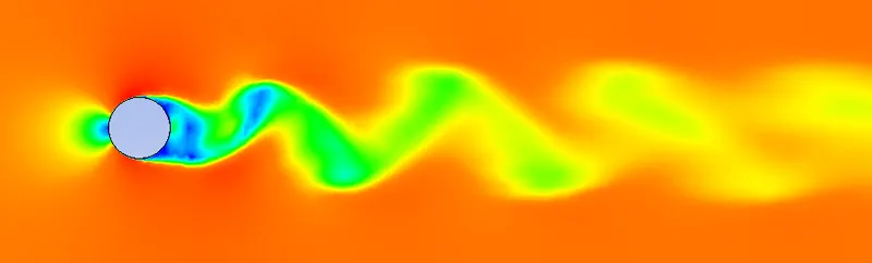
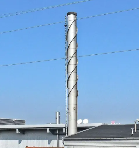
In the flow, in which Vortex street occurs, vortices are created at the back of the object detaching periodically from either side of the body. Due to this unsteady flow, body experiences pressure fluctuations and will tend to move towards the low pressure zone, causing vibrations which may lead us to severe consequences. If the Vortex frequency will match object's natural frequency object will resonate. This vibration is the reason of overhead power line wires humming, also fluttering automobile whip radio antennas at some speeds, Tall chimneys constructed of thin walled steel could be significantly flexible which may cause violent vibrations that can damage or destroy the chimney. Fortunately engineering is the field which is responsible for solving important problems. In order to avoid vibrations in cylindrical shaped objects a longitudinal fin can be fitted on the downstream side, which provided is longer than the dimeter of the cylinder, will prevent the eddies from interacting and consequently they remain attached.
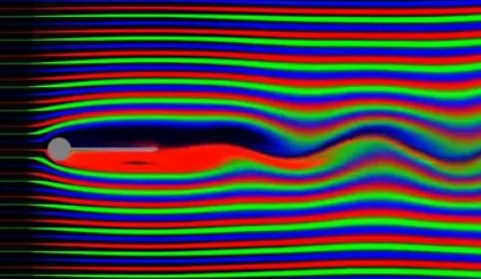
As you see how the fin attached at the back of the cylinder helps to delay the votrex street phenomenon.
Case Setup
- Geometry
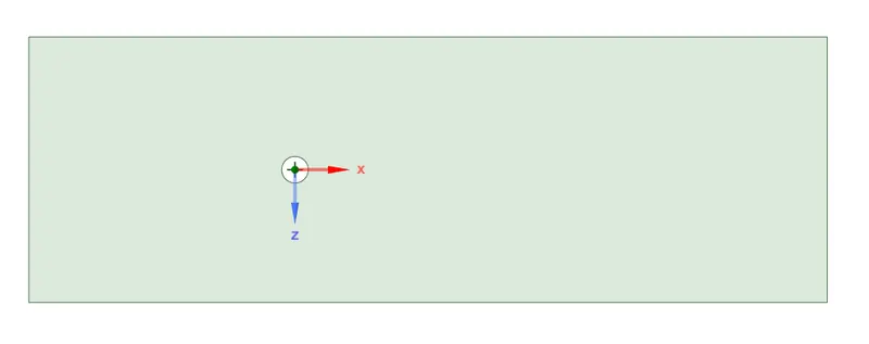
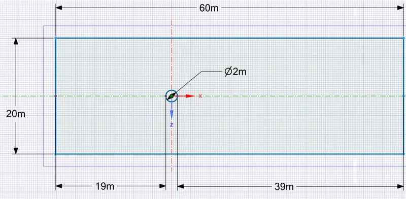
In order to create enclosure around the circle we need to specify dimensions in advance. Our reference point is the center of the circle from which the left edge of the rectangle will be located with the distance equal 10times the diameter of the circle, therefore the distance will be 19m (from the circle), the right edge will be located 20times the length of the diameter, thus 39m away from the circle, the top and the bottom edges will be 10 times the dimeter length away from the center of the cylinder, meaning the width of the enclosure will be 20m.
- Mesh
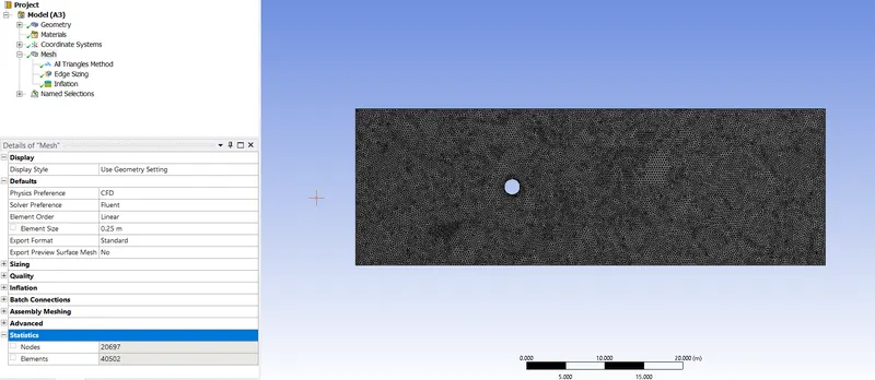
As you see, we have generated pretty fine mesh with the element number of 40502. As a method we are using "Triangles" to generate tetra mesh for CFD analysis.
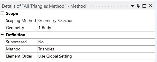
While meshing we are also using "Edge sizing" in order the circle which will be aerodynamic object, to have smooth shape (Close to perfect circle).
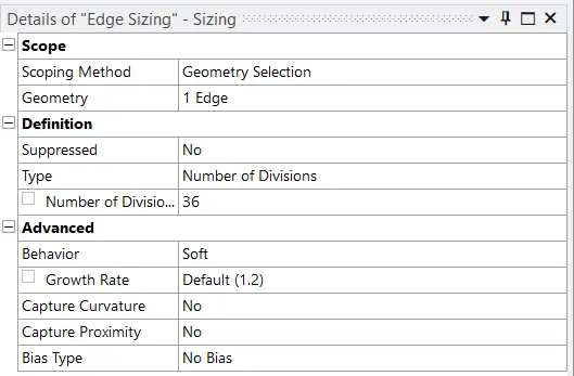
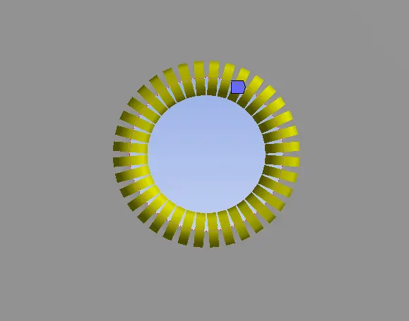
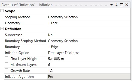
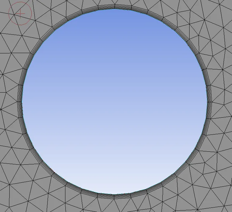
In addition we also use inflation layers to more preperly capture boundary layer thickness.
Part 1: Simulate the flow with the steady and unsteady case and calculate the Strouhal Number for Re= 100.
- Steady state case Re 100
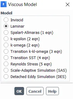
As a flow solver we are using Laminar model
As a fluid we are using user-defined material
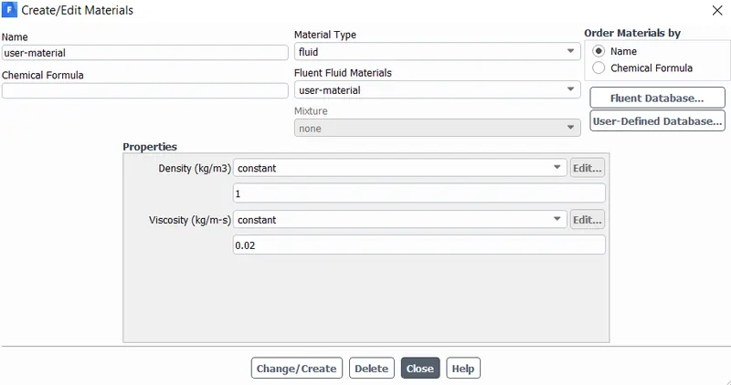
Density of the fluid is approximately the same as air, however our Viscosity is 0.02kg/m/s
As we know Reynolds number in this case equal to 100 and freestream velocity is 1 m/s (This will be shown in boundary conditions), Therefore viscosity must be 0.02
`Re = (U*L)/nu` - Where `U` is a freestream velocity and equals to 1m/s
`L` is a characteristic length (the diameter of the circle in out case) 2meters.
`nu` is a kinematic viscosity
`100 = (1*2)/nu => nu = 2/100 = 0.02`
- Boundary Conditions
Inlet
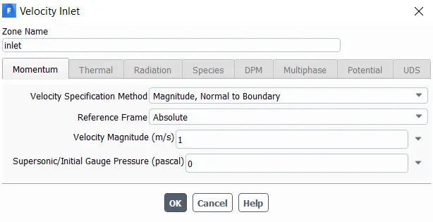
Outlet
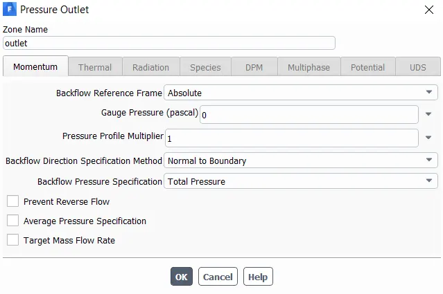
Cylinder Wall
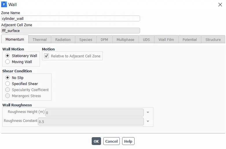
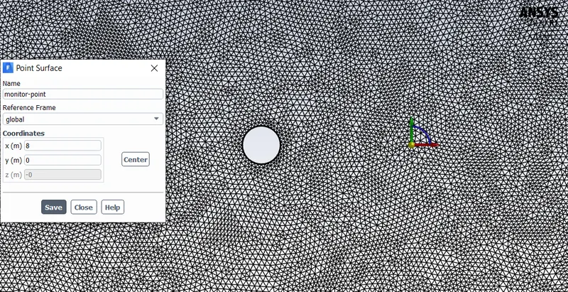
While solving the problem we have several monitoring parameters. We are monitoring forces: lift and drag. Furthermore, we are monitoring velocity fluctuation at the back of the circle using the monitor-point.
Monitor-point
- Results
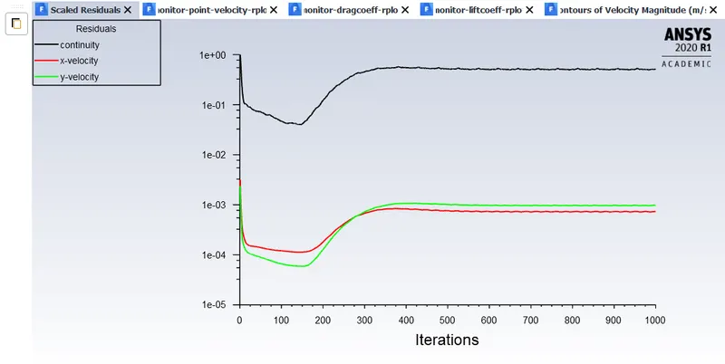
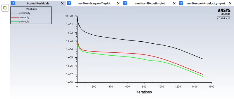
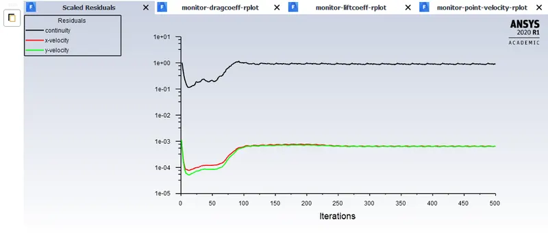
Scaled residuals
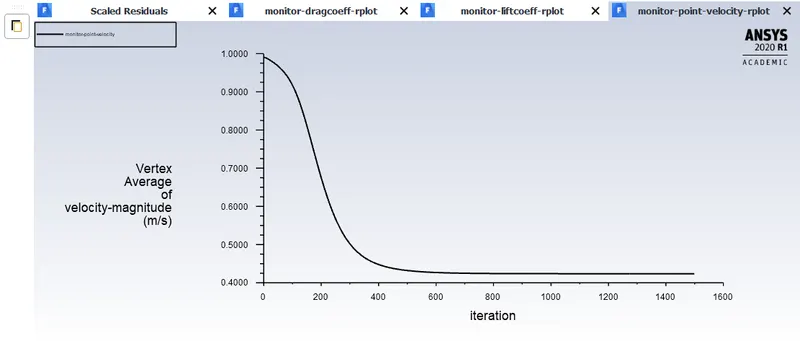
Vertex Average of Velocity-magnitude
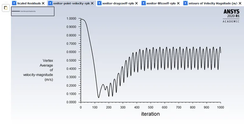
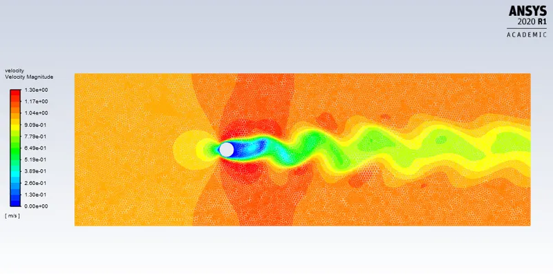
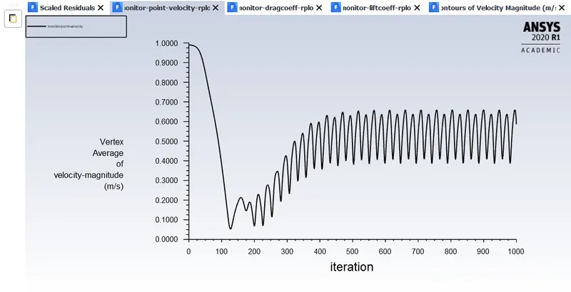
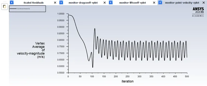
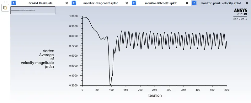
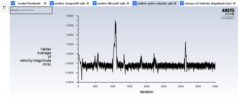
As Shown in the plot above, velocity starts to oscillate, that is the result of Vortex Shedding.
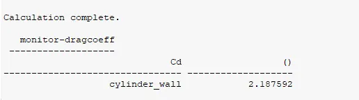
Drag Coefficient
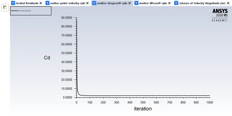
Drag coefficient appears to be 2.187
Lift Coefficient
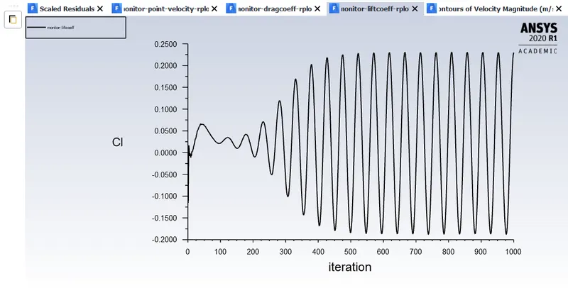
Lift coefficient changes it's value due to periodic pressure change at the either side of the circle. Average value of the lift coefficient is approximately 0.024.
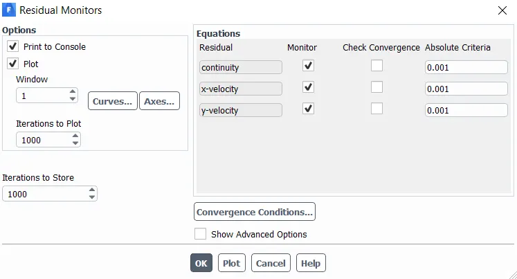
Note: we turned off the "check convergence" because as you see in the figure above before vortex shedding starts several hundred iterations are already completed, therefore we turned off convergence check and were monitoring the results manually.
Contours of Velocity Magnitude
We need to calculate the Strouhal Number, which is a dimensionless number describing oscillating flow mechanisms.
`St = (f*L)/U` - Where `f` is a frequency of Vortex Shedding
`L` is a characteristic length, Circle diameter in our case
`U` is a frestream velocity
As we are solving steady state it's impossible to calculate Strouhal number due to our simulation is not time-dependent and in the Strouhal number equation we have a frequency as a variable. Therefore, to calculate the Strouhal number we are simulating transient state as well.
- Transient (Unsteady) state
In this case every step is the same as in the steady state, except one. Instead of iterations now we have time steps and the simulation end time.
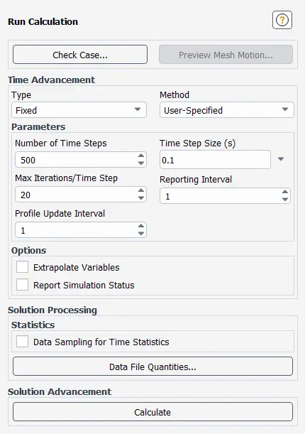
As the time step is 0.1sec and we have 500 time steps, Simulation end time will be `0.1*500 = 50sec`
- Results
Scaled Residuals
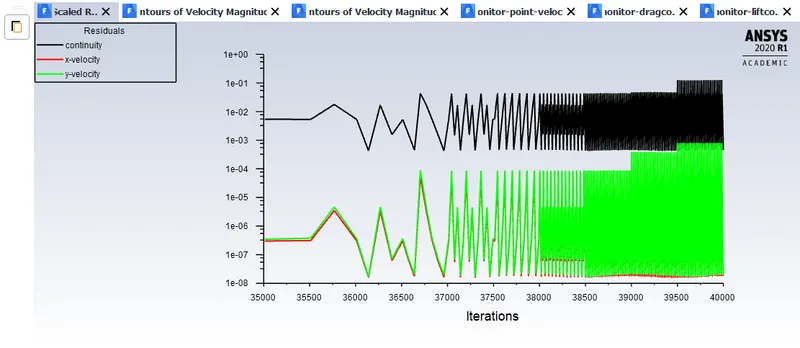
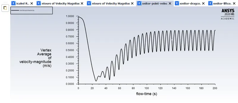
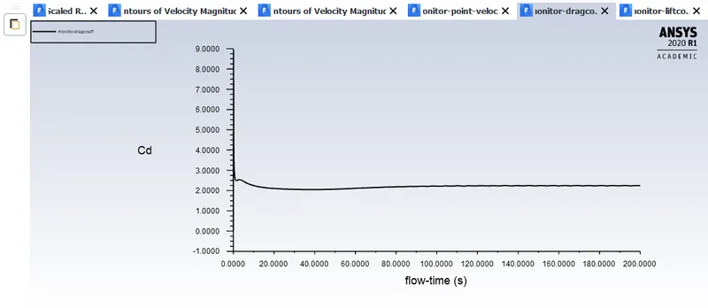
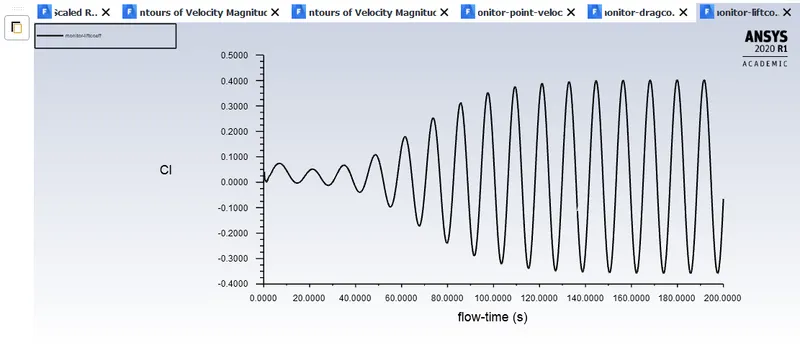
As you see in the Figure above. Number of iteration equals to 40K and the flow time was 200sec as shown in the Figures below. We had to run the simulation several times to reach desired convergence.
Vertex Average of Velocity-magnitude
Drag coefficient
Lift coefficient
Frequency
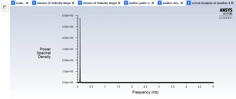
According to the following equation in order to find the value of the Strouhal number, firstly we can find out the converged frequency of vortex.
`St = (f*L)/U` - Where `f` is a frequency of Vortex Shedding
`L` is a characteristic length, Circle diameter in our case
`U` is a frestream velocity
Fromm the report file of the Frequency. While the Power Spectral Density equal to 5.72 the frequency is 0.084957518. Therefore the Strouhal number will be defined with the given equation.
`St = (f*L)/U = (0.084957518*2)/1` = 0.1699
Part 2:
- 1) Calculate the coefficient of drag and lift over a cylinder by setting the Reynolds number to 10,100,1000,10000 & 100000. (Run with steady solver)
- Steady State case Re 10
- Results
Scaled Residuals
Vertex Average of Velocity-magnitude
Drag coefficient
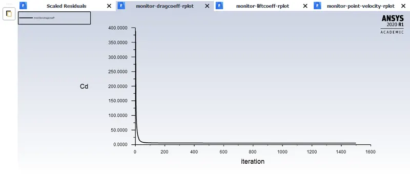
Drag coefficient value is approximately 5.4

Lift coefficient
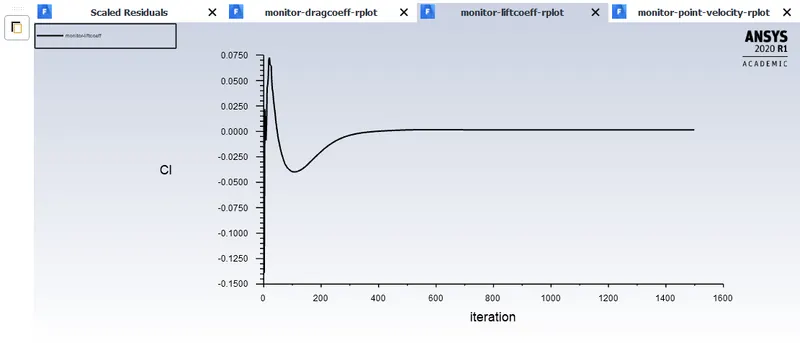
Lift coefficient value is 0.00152

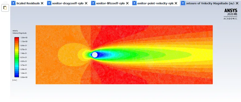
Velocity Contours
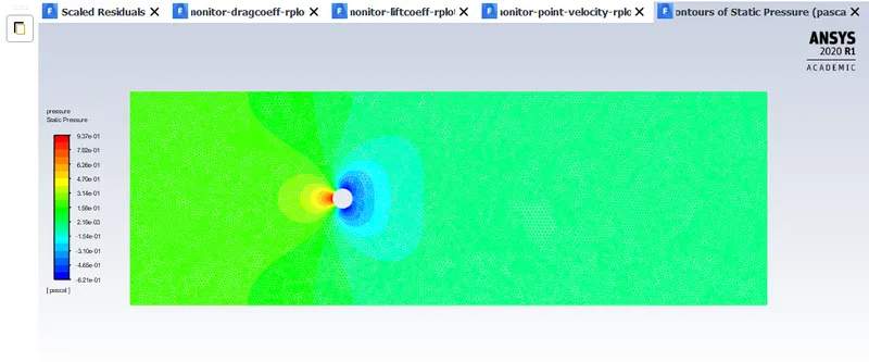
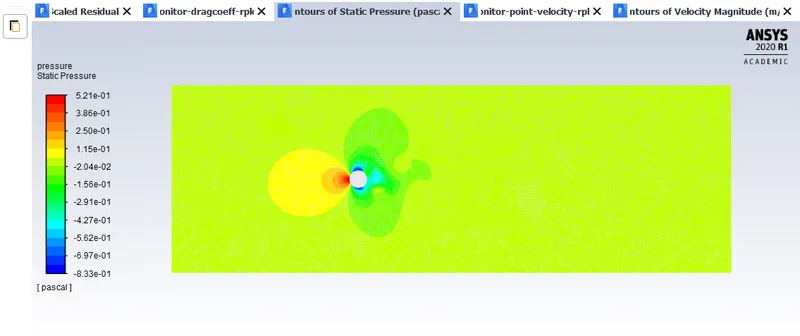
Pressure Contours
- Steady State case Re 100
- Results
Scaled Residuals
Vertex Average of Velocity-magnitude
Drag Coefficient
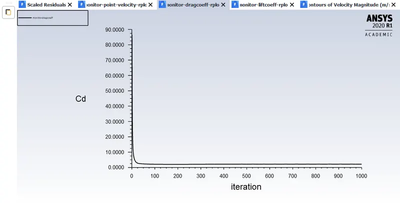
Drag coefficient value is approximately 2.1876
Lift coefficient
The mean value of the Lift coefficient is 0.024
Velocity Contours
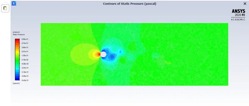
Pressure Contours
- Steady State case Re 1000
- Results
Scaled Residuals
Vertex Average of Velocity-magnitude
Drag Coefficient
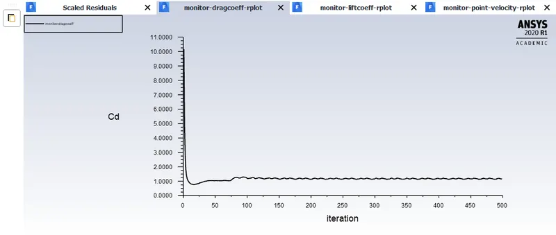
Drag coefficient value is approximately 1.16

Lift coefficient
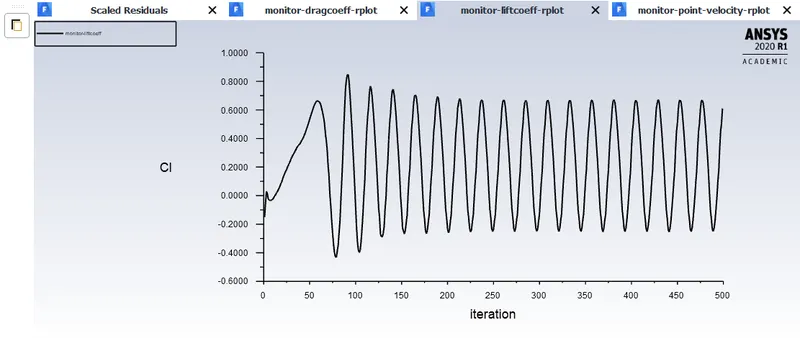
The mean value of the Lift coefficient is 0.22
Velocity Contours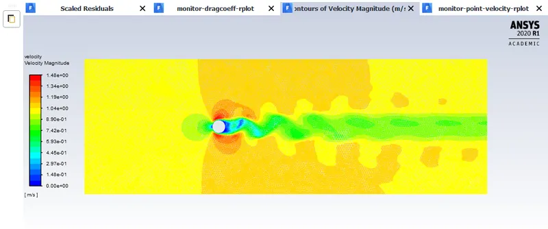
Pressure Contours
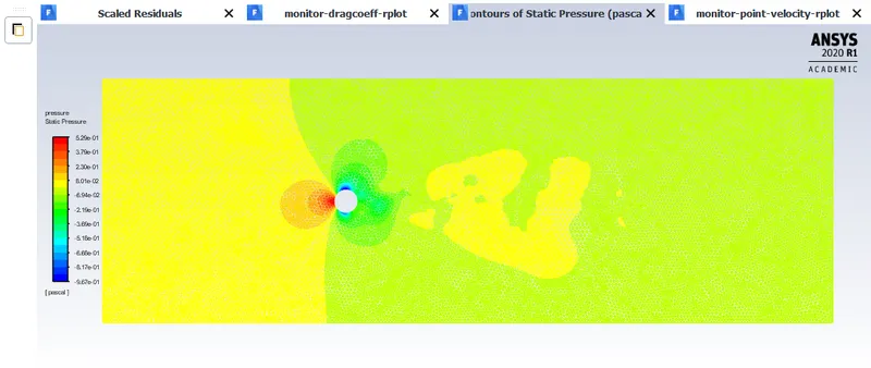
- Steady State case Re 10000
- Results
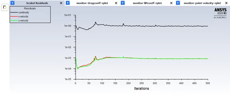
Scaled Residuals
Vertex Average of Velocity-magnitude
Drag Coefficient
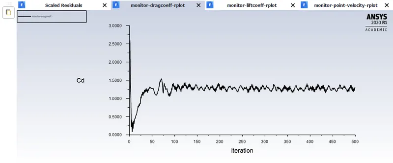
Mean value of the Drag coefficient is approximately 1.244
Lift coefficient
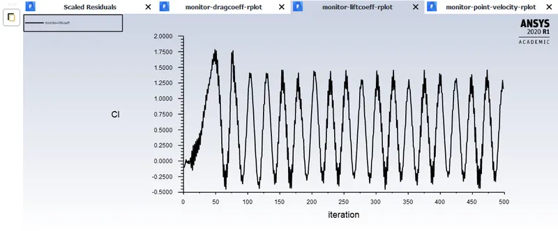
The mean value of the Lift coefficient is 0.523
Velocity Contours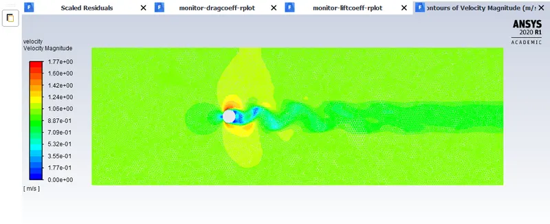
Pressure Contours
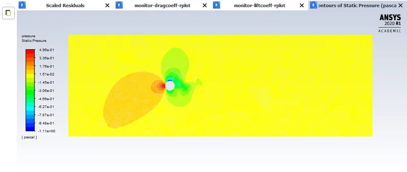
- Steady State case Re 100000
- Results
Scaled Residuals
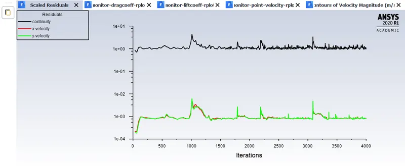
Vertex Average of Velocity-magnitude
Drag Coefficient
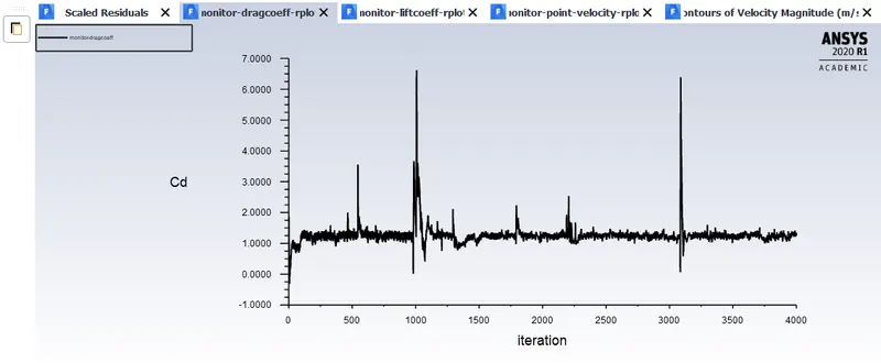
Mean value of the Drag coefficient is approximately 1.2614
Lift coefficient
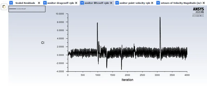
The mean value of the Lift coefficient is 0.556
Velocity Contours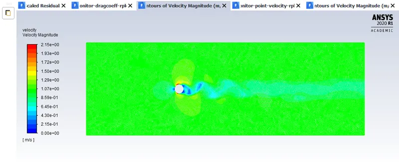
Pressure Contours
- Reynold's number vs Drag coefficient
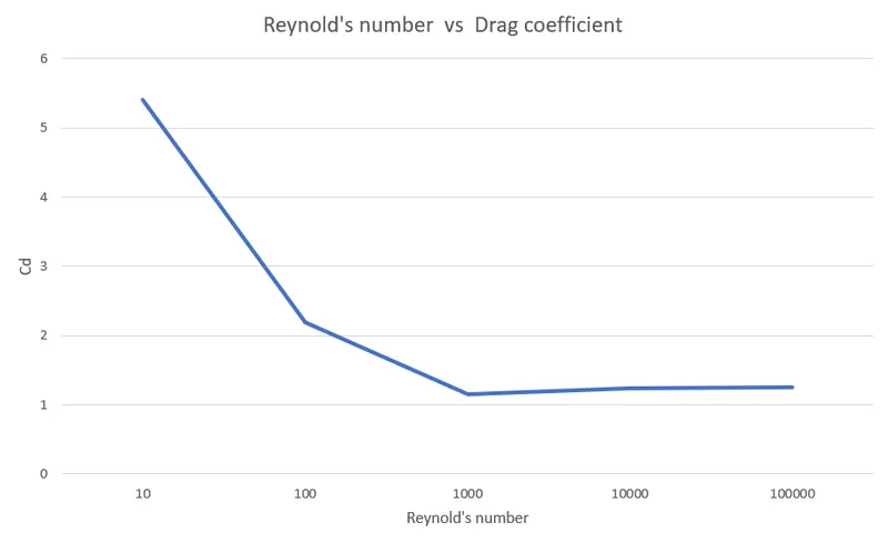
As you see in the Figure above, while Reynold's number increases Drag coefficient drops. At the first glance it seems to be unintuitive, however we should mention that drag could be divided into 2 parts: pressure drag and turbulent drag.
While the Reynold's number increases, the flow around the sphere tends to be more turbulent, therefore pressure drag drops dramaticaly. That's why a golf ball has a dimples to cause turbulent flow around the ball in order to decrease pressure drag and make the ball travel much further distance than a smooth one.
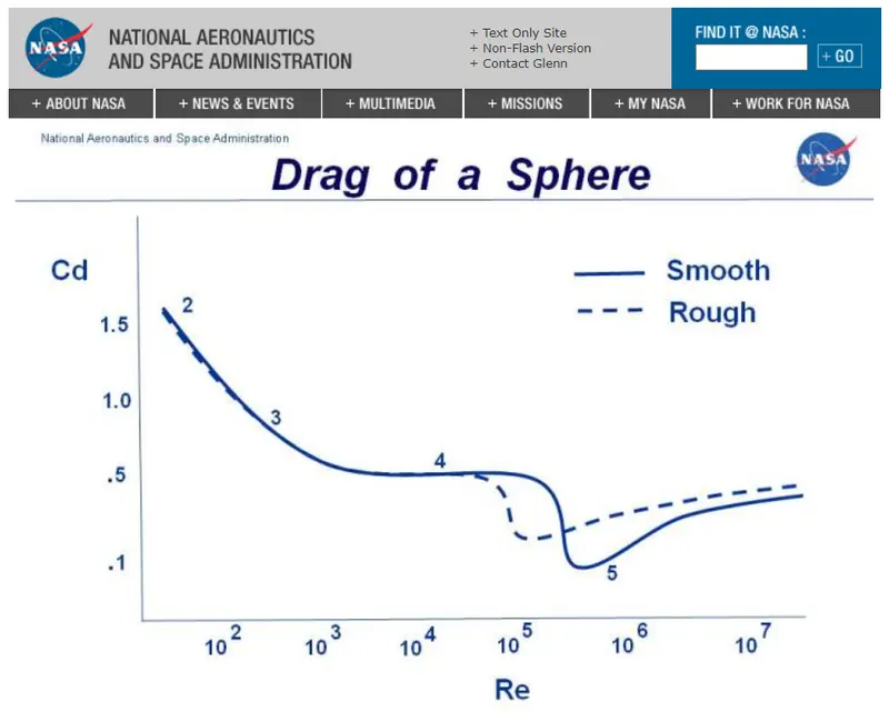
The figure above which is provided by Nasa shows the same trend in Reynold's number and drag coefficient dependence as we got from our study using Ansys Fluent.
Conclusion
We simulated all the cases and found out that, while Reynold's number was 10 we did not encounter Von Karman Vortex Shedding, however while simulating every case in which Reynold's number was equal or greater than 100 we experienced Vortex Shedding. Furthermore, after completing different Reynold's number cases we explaned why drag coefficient was decreasing while we increased Reynold's number.
In addition we simulated transient state while Reynold's number was 100 and calculated a Strouhal number.
Reference Materials:
https://www.grc.nasa.gov/www/k-12/airplane/dragsphere.html
https://sci-hub.do/https://www.sciencedirect.com/science/article/pii/S0307904X08000243
https://en.wikipedia.org/wiki/Kármán_vortex_street
https://chart-studio.plotly.com/~stevenpuglisi/2.embed
http://www2.eng.cam.ac.uk/~mpj1001/learnfluidmechanics.org/LFM_blank_notes/handout_8_v3.pdf