Steady Vs Unsteady flow over a cylinder
Aim:simulate the flow over a cylinder and explain the phenomenon of Karman vortex street.
PART-I
- Simulate the flow with the steady and unsteady case and calculate the Strouhal Number for Re= 100.
PART-II
- Calculate the coefficient of drag and lift over a cylinder by setting the Reynolds number to 10,100,1000,10000 & 100000. (Run with steady solver)
- Discuss the effect of Reynolds number on the coefficient of drag. [ Results should be validated with any standard literature and error should be within 5 %]
Expected results:-
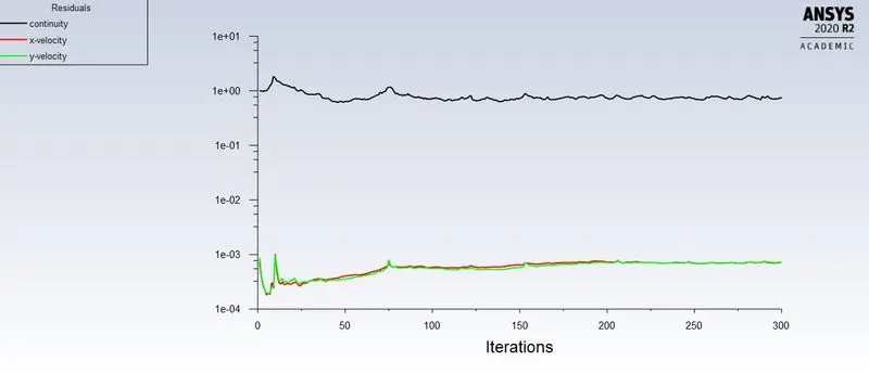
- In both approaches, show that the flow has converged. That is, what quantities or plots need to be looked at to determine that the flow has converged?
- Plots of the coefficient of drag and lift.
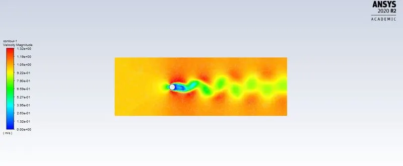
- Plots to show vortex shedding behind the cylinder.
- Mention the preferred material at the end of the challenge .
Introduction:
Vortex shedding is an oscillating flow that takes place when a fluid such as air or water flows past a bluff (as opposed to streamlined) body at certain velocities, depending on the size and shape of the body. In this flow, Vortices are created at the back of the body and detach periodically from either side of the body, forming a von Karman vortex street. The fluid flow past the object creates alternating low-pressure vortices on the downstream side of the object. The object will tend to move toward the low-pressure zone. Moreover, von Kármán vortex street is a repeating pattern of swirling vortices, caused by a process known as vortex shedding, which is responsible for the unsteady separation of flow of a fluid around blunt bodies.
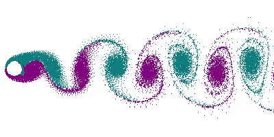
Animation of vortex street created by a cylindrical object; the flow on opposite sides of the object is given different colors, showing that the vortices are shed from alternating sides of the object.
Strouhal Number:
The Strouhal number is a dimensionless number describing oscillating flow mechanisms,
The Strouhal number is often given as,
St=fL/V.
where f is the frequency of vortex shedding
L is the characteristic length
U is the flow velocity
Procedure:
Geometry:
An infinitely long circular cylinder of diameter D=2.0 m is placed in an otherwise undisturbed uniform crossflow. The lateral boundary and the exit boundary in the far wake are placed at 10 Dand 20D from the centre of the circular cylinder, respectively. The cylinder is used to be drawn in SpaceClaim.
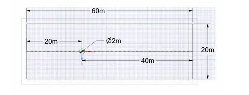
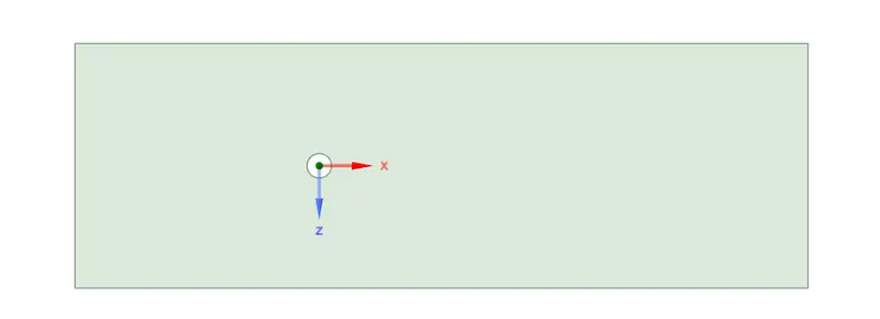
Converting the geometry into the surface by using command pull and select. Also, delete the inside the circle to carry out the simulation.
2.Mesh:
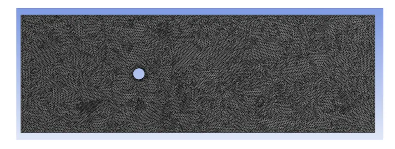
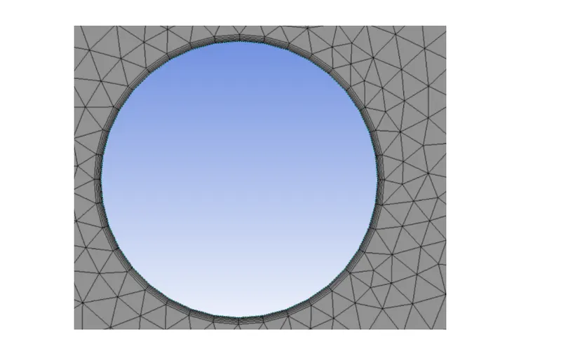
- Now in the mesh mode we set the mesh size and give inflation layers to the cylinder.
- The mesh size given is 0.25m and inflation layers are 6 no.s and with first layer thickness and first layer height of 0.005.
3.Solving:
Steady State Simulation:
PLOTS: In both i.e. steady and unsteady state simulations, following plots are to be shown:
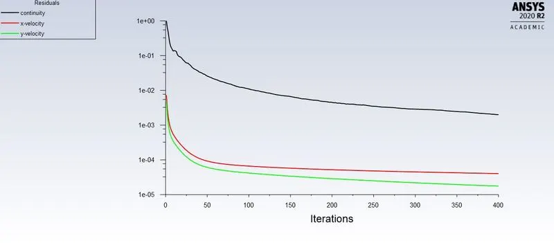
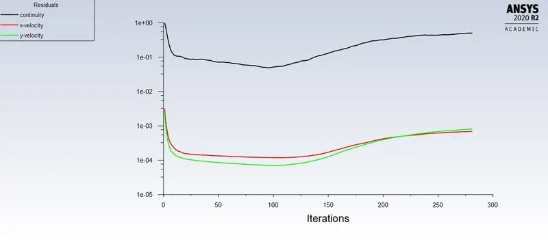
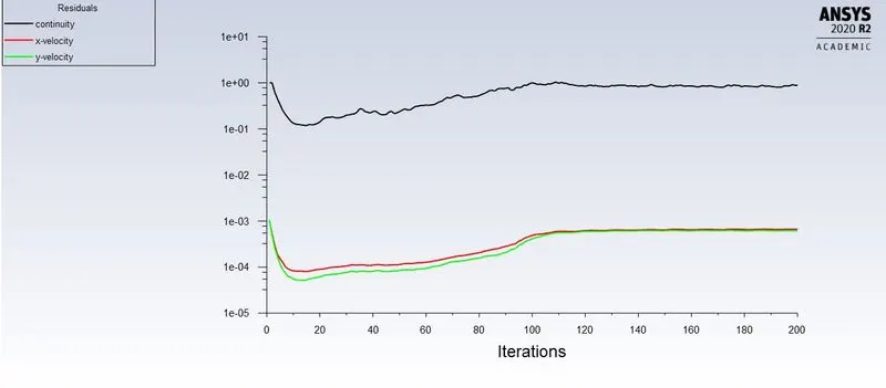
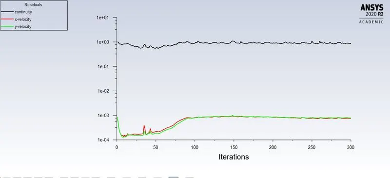
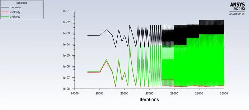
- Residual plot - This plot helps us in knowing at what point convergence is achieved.
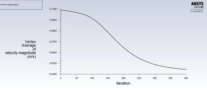
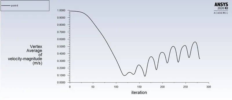
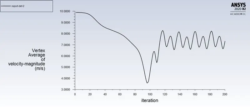
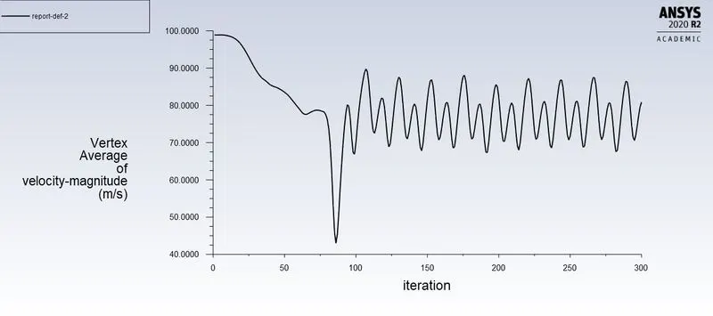
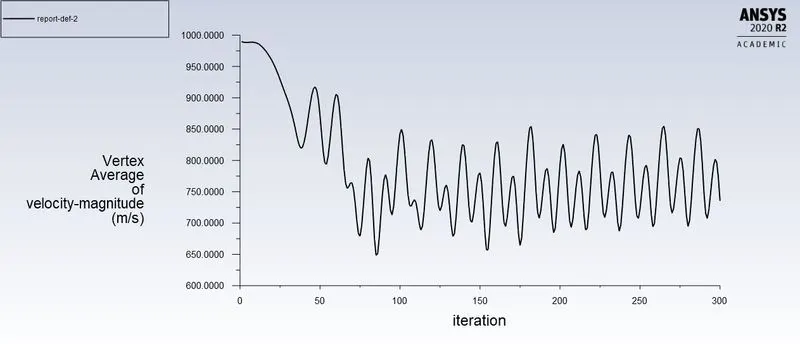
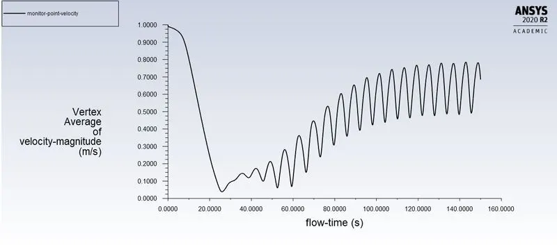
- Monitor point velocity plot - A monitor point is placed at a distance of 8m from the cylinder inorder to calclate the velocity at that point.
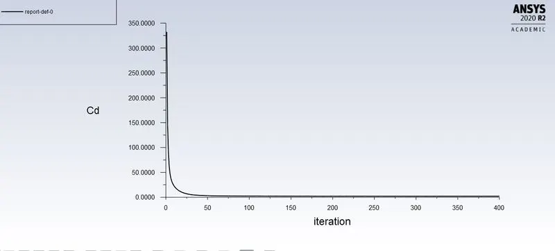
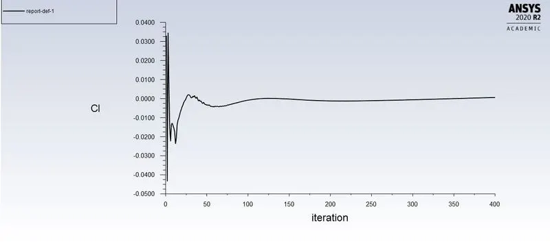
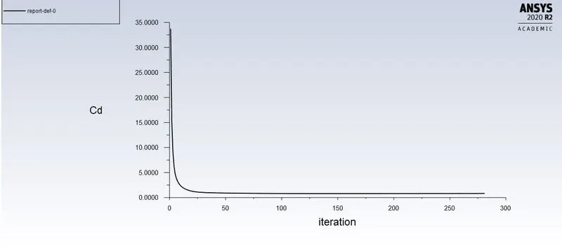
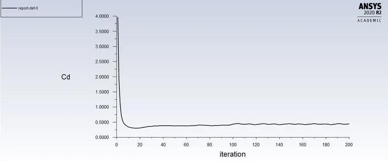
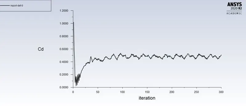
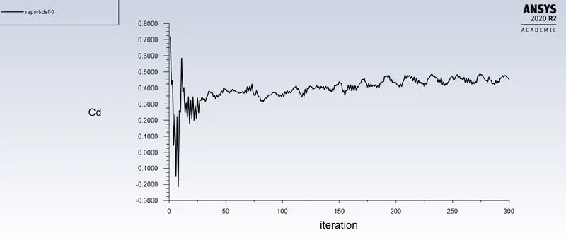
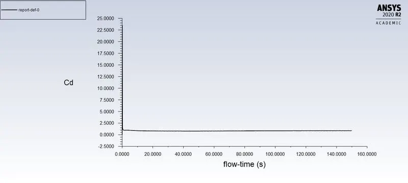
- Drag coefficient plot - To calculate the drag coefficient.
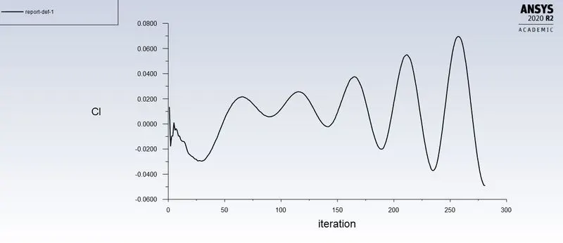
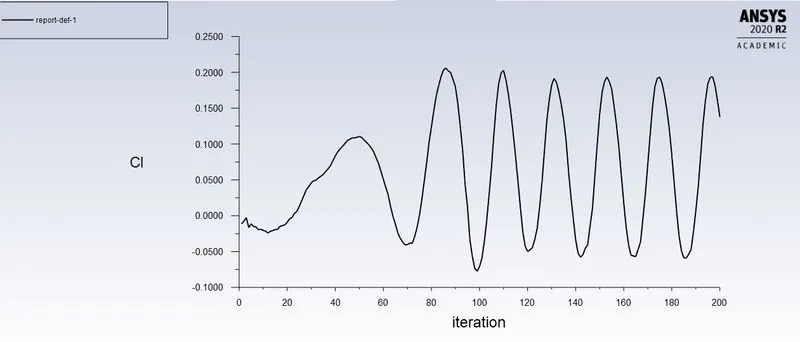
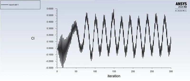
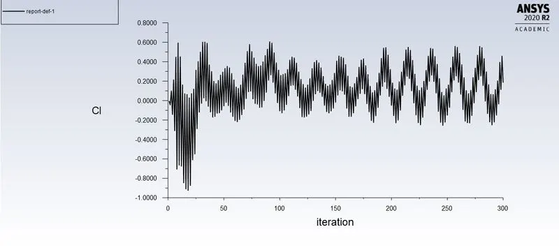
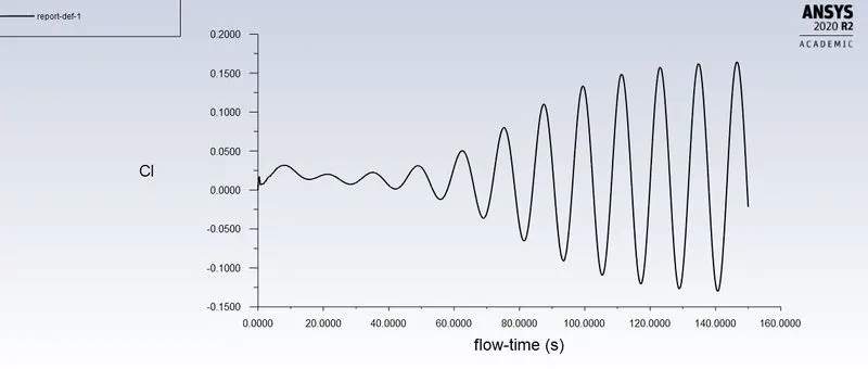
- Lift coefficient plot - To calculate the lift coefficient.
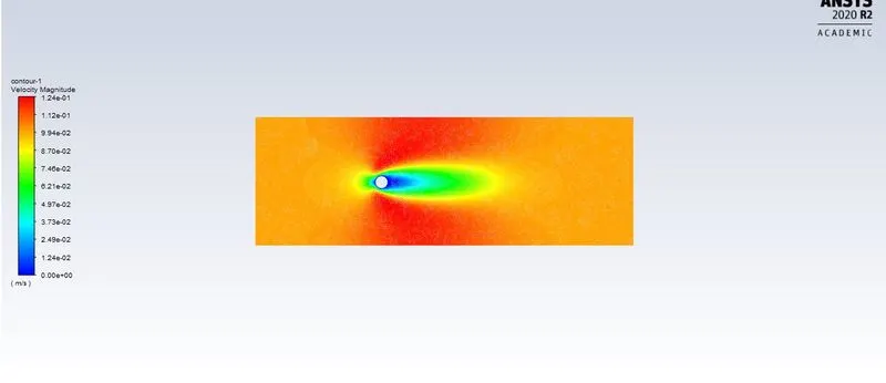
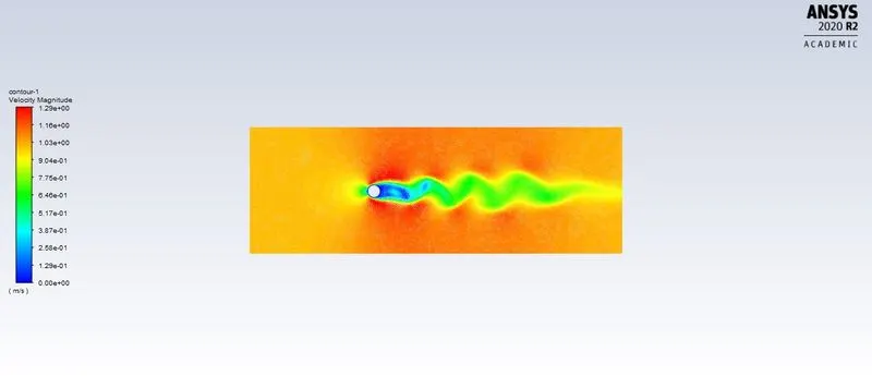
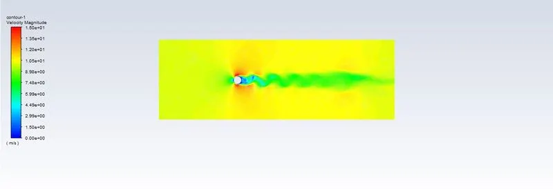
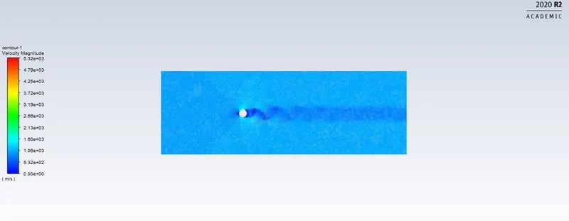
- Velocity contour plot - To see the velocity changes in the flow over the cylinder.
case 1: For Re=10 where viscosity=0.02 and velocity =0.1 m/s.
Residuals:
Monitor point velcoity:
Drag co-efficient:
Lift co-efficient:
Velocity contour:
Animation:
case 2: For Re=100 where viscosity=0.02 and velocity =1 m/s.
Residual:
Monitor point velocity:
Drag co-efficient:
Lift co-efficient:
Velocity contour:
Animation:
case 3: For Re=1000 where viscosity=0.02 and velocity =10 m/s.
Residual:
Monitor velocity point:
Drag co-efficient:
Lift co-efficient:
Velocity contour:
Animation:
Case 4 :for Re 10000 where viscosity 0.02 and velocity 100 m/s.
Residual:
Monitor point velocity:
Drag co-efficient:
Lift co-efficient:
Velocity contour:
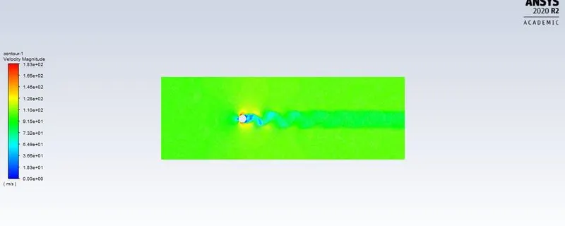
Animation:
Case 5 :for Re 100000 where viscosity 0.02 and velocity 1000 m/s.
Residual:
Monitor point velocity:
Drag co-efficient:
Lift co-efficient:
Velocity contour:
Animation:
Transient state:
For Re=100 where viscosity=0.02 and velocity =1 m/s.
Residuals:
Monitor point velocity:
Drag co-efficient:
Lift co-efficient:
Velocity contour:
Animation:
Reynolds number drag co-efficient lift co-efficient
10 2.12 0.000565
100 0.8333 -0.04
1000 0.4455 0.137611
10000 0.4572 0.0666
100000 0.44787 0.18397
Unsteady =100 0.85707 0.12826129
Strouhal number:
St=fd/V
F=number of peaks/flow
=3/20
=0.15
St=0.15*2/1
=0.3
Conclusion:
- The results for the both the Steady state and Transient state are converged
- Using the transient state solver we are getting the VortexShedding because the solver is solving for each time step and requires more time to solve the entire domain to be converged
- Compartively the transisent State is the best method to get the accurate result because it is time Dependent whereas the Steady state is independent of time.
- Transient simulation will be preferably chosen over steady state simulation in this type of problems.
Material preffered for instability reduction:
Design can be change to reduce instability by adding porous and dimple in the surface.
We can add device on the structure for suppression of vortex-induced vibration of cylinder.
a) spiral strake b) splitters c) axial slats d) streamlined fairing e)ribboned cable f)pivoted guiding vane h)spoiler plates