SIMULATION OF FLOW OVER A CYLINDER
SIMULATION OF FLOW OVER A CYLINDER:
AIM:
To simulate the flow over cylinder with steady and unsteady case and coefficients of drag and lift over a cylinder by setting the various Reynolds number.
INTRODUCTION:
Performing 2D simulation of cylinder,setting up the cases for particular Reynolds number and controls the reynolds number by creating customized fluids and its properties and visualizing animations and vortex shedding.
THEORY:
Flow around circular cylinders includes a variety of fluid dynamics phenomena, such as separation, vortex shedding and the transition to turbulence.
A vortex street will form only at a certain range of flow velocities, specified by a range of Reynolds number (Re), typically above a limiting Re value of about 90.
Reynolds number:The Reynolds number for a flow is a measure of the ratio of inertia to viscous force in the flow of a fluid around a body or in a channel, and may be defined as a nondimensional parameter of the global speed of the whole fluid flow.
`Re=(rho*V*D)/mu`
Vortex shedding is an oscillation flow that takes place when a fluid such as air or water flows past a bluff body at certain velocities,depending on size and shape of the body.
Frequency is time dependent and its the ratio of no.of iteration cycles to difference between intervals.
Strouhal number: Oscillating flow mechanism when fluid passes.Strouhal number increases with Reynolds number.St depends on Re.
`St = (fL)/u`
Where f=frequency,
L=length of cylinder,
u=velocity in m/s
For Re number 100-100000,St=0.16-0.2
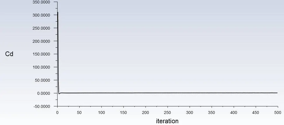
Drag force:
Resistance force caused by the motion of body through through a fluid,such as air/water/user defined functions.
Drag force acts opposite to the direction of oncoming flow velocity.
`f_d=(1/2)(C_d*rho*A*V^2) ;`
Where `C_d`=Drag coefficient;
`rho`=density of fluid;
v=speed of velocity;
A= Frontal area of cross section.
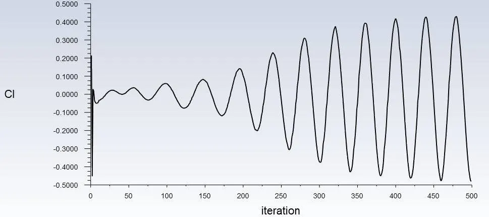
Lift force:
A fluid flowing around surface of an object exerts a froce on it.
A force perpendicular to oncoming flow direction.
`f_l=(1/2)(C_l*rho*A*V^2) ;`
WORKFLOW:
1.Geometry:
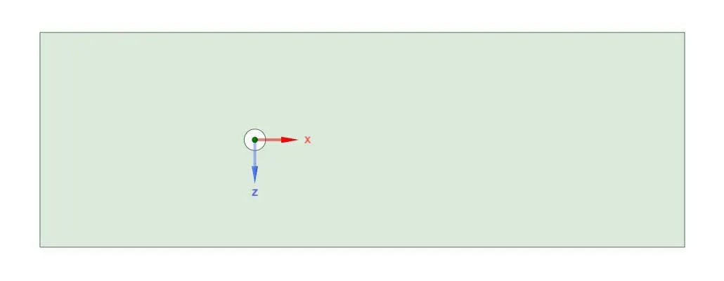
Rectangular computational design,2D single slice of cylinder of 2m is placed between 10D internally and 20D from extrenal layer with various inlet velocity with respect to various reynolds number.Top and bottom walls are symmetry boundary.
2.MESH:
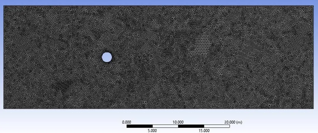
GENERATED MESH:
| Reynolds number | Case | Element size in m | First layer thickness in m | Cell count | Number of divisions |
| 10 | Steady | 0.25 | 0.005 | 40502 | 36 |
| 100 | Steady | 0.25 | 0.005 | 40502 | 36 |
| 1000 | Steady | 0.25 | 0.001197 | 42038 | 100 |
| 10000 | Steady | 0.25 | 0.001197 | 42038 | 100 |
| 100000 | Steady | 0.25 | 0.001197 | 42038 | 100 |
| 100 | Transient | 0.25 | 0.001197 | 42038 | 100 |
Ansys adaptively refine the mesh near the cylinder.All triangle method has been selected for meshing.
Edge sizing has been made for selection of body selction and no. of divisions
Inflation layer has been made by first cell thickness based on `y^+` number and maximum layer also selected here.
3.SETUP:
Here setup has been made based on the two cases. i.e., steady and unsteady case.
Pressure based solver is steady state solver for which is really small no.based.
Velocity formulaiton is absolute.
Flow can be reynolds number.For lower reynolds number and `y^+` is between 0-5 , Then K-`omega`SST model is chosen and for higher reynolds number and `y^+` is between 30-300 K-`epsilon`model can be chosen.
Here we chose as per various cases given such as Re=10,100,1000,10000,100000
Boundary condition can be assigned in cell zone.
Fluid materials is air is kept as user defined and its density is 1kg/m^3 and viscous model is 0.02kg/ms can be kept.
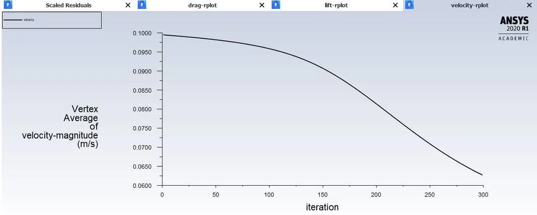
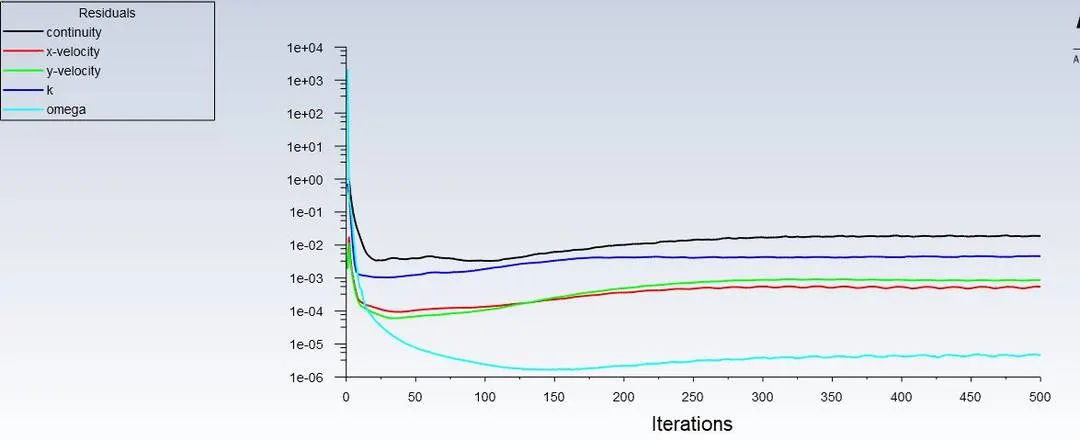
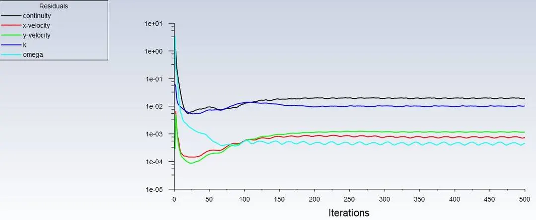
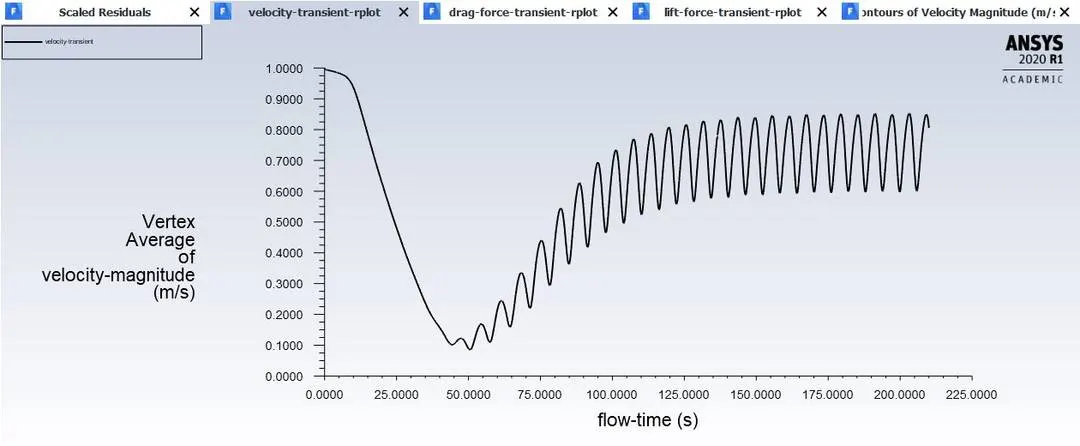
Surface report file and plot has been created for vortex average and force report file and plot for drag force and lift force and velocity residuals for iteration can be found as plot.
As of now, Initial condition,Boundary condition ,Material properties are done.
Then standard initialisation is done by computing from input for assigning initial values.
For steady case,number of iteration have to be set up while for unsteady cases,number of time steps and size have to be set up.
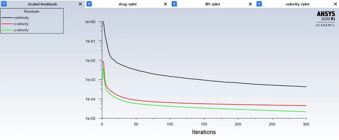
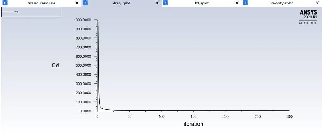
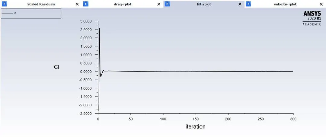
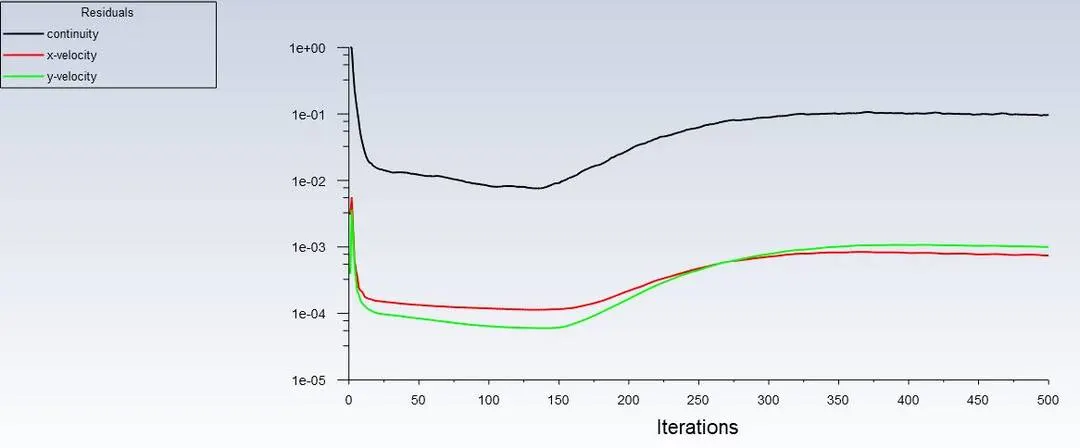
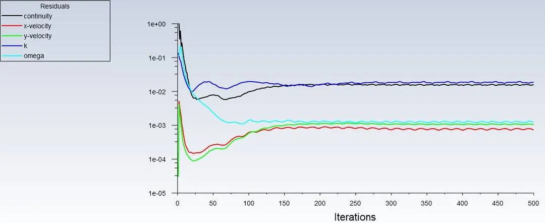
As we increases no. of iterations,it tries to reaches zero(keeps decreasing)
No. of iteration for convergence can be found
When your simulation has no change on all the convergence criteria,after certain iteration or timesteps,we consider that solution has reached a steady state. i.e.,converged.Even we run further long, you won't be able to see any changes in case.
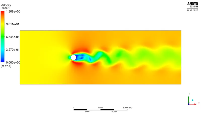
Solution Animations are created for visualizing of vortex shedding of fluid flow over a cylinder.
Followed by the processes post processing has simulated.
4.RESULTS:
When steady case,
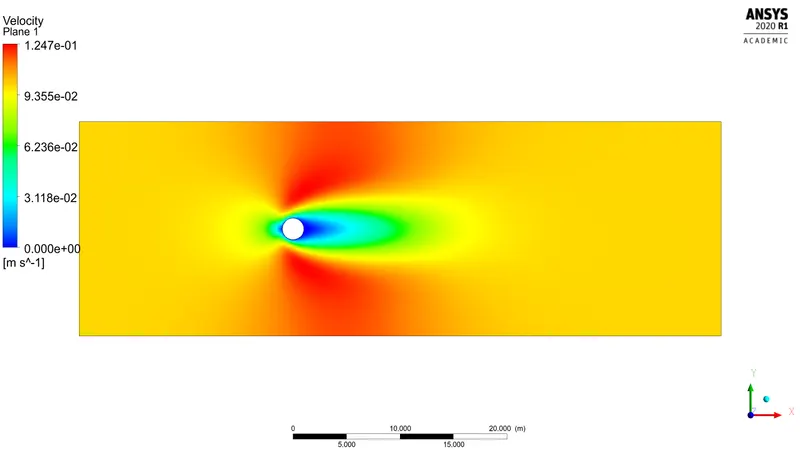
1.Re=10,`rho=1(kg)/m^3`,Dia=2m,`mu=0.02(kg)/(ms)`
`Re=(rho*v*D)/mu ;v=(Re*mu)/(rho*D)`
`v=(0.02*10)/(2*1)`
v=0.1m/s
Then we can setup properties and initialise.Followed by initialisation run the simulation and get the plots as below.
VORTEX SHEDDING BEHIND THE CYLINDER:
ANIMATION VIDEO:
RESIDUAL VELOCTY PLOT:
DRAG FORCE PLOT:
LIFT FORCE PLOT:
VERTEX AVERAGE OF VELOCITY-MAGNITUDE PLOT:
2.Re=100,`rho=1(kg)/m^3`,Dia=2m,`mu=0.02(kg)/(ms)`
v=1m/s
VORTEX SHEDDING BEHIND THE CYLINDER:
ANIMATION VIDEO:
RESIDUAL VELOCTY PLOT:
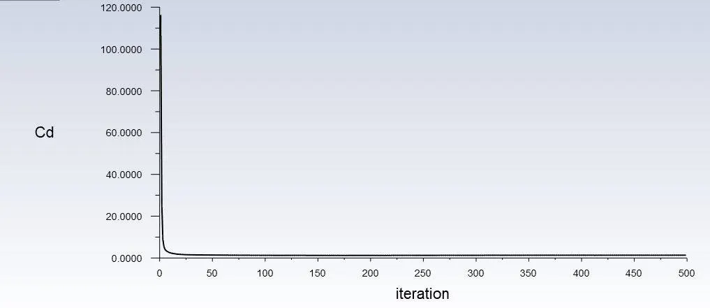
DRAG FORCE PLOT:
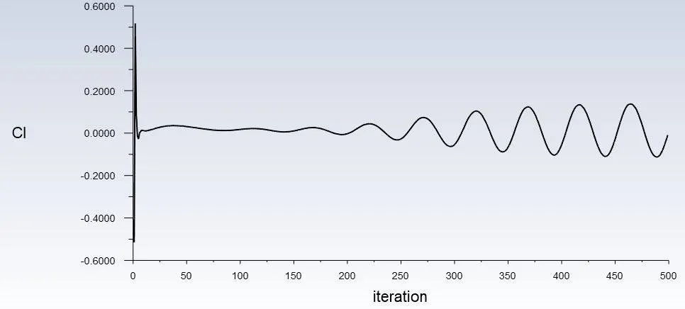
LIFT FORCE PLOT:
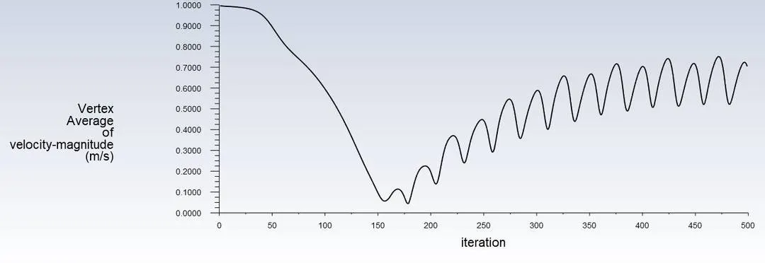
VERTEX AVERAGE OF VELOCITY-MAGNITUDE PLOT:
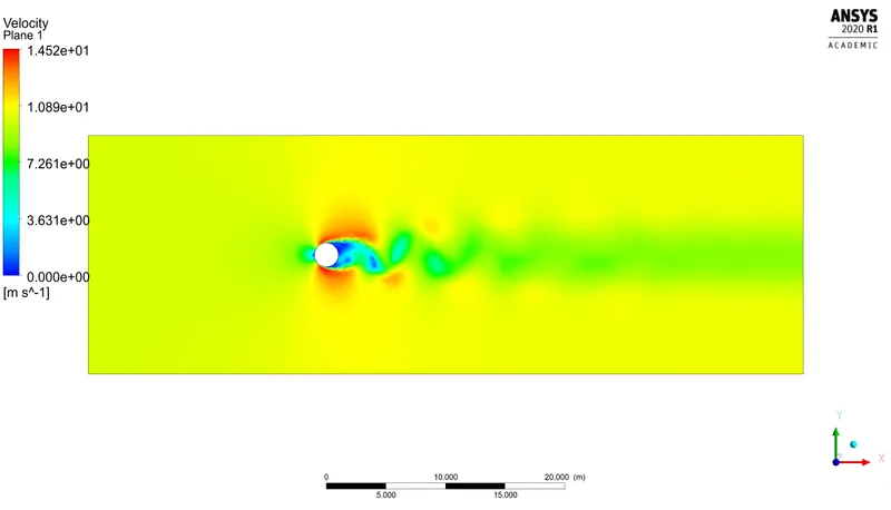
3.Re=1000,`rho=1(kg)/m^3`,Dia=2m,`mu=0.02(kg)/(ms)`
v=10m/s
VORTEX SHEDDING BEHIND THE CYLINDER:
RESIDUAL VELOCTY PLOT:
DRAG FORCE PLOT:
LIFT FORCE PLOT:
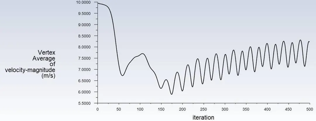
VERTEX AVERAGE OF VELOCITY-MAGNITUDE PLOT:
4.Re=10000,`rho=1(kg)/m^3`,Dia=2m,`mu=0.02(kg)/(ms)`
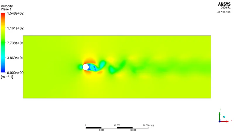
v=100m/s
VORTEX SHEDDING BEHIND THE CYLINDER:
RESIDUAL VELOCTY PLOT:
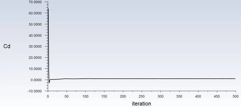
DRAG FORCE PLOT:
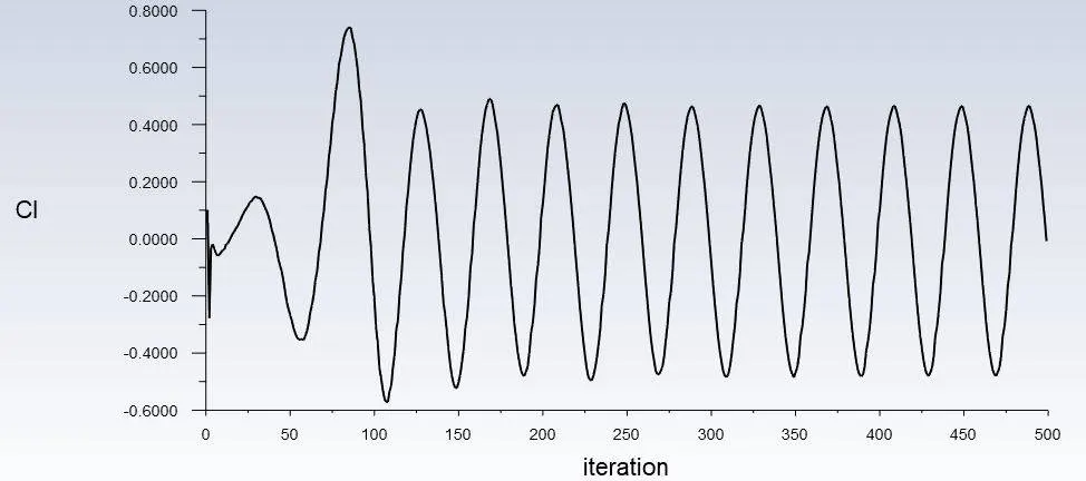
LIFT FORCE PLOT:
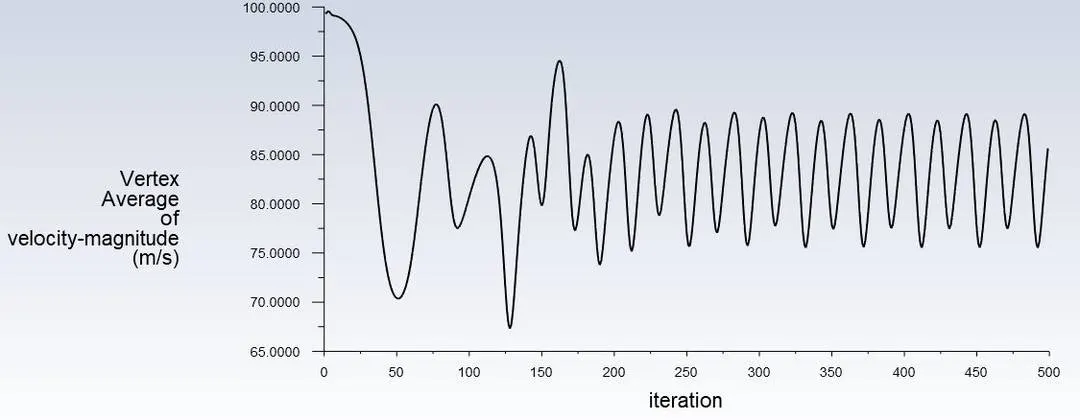
VERTEX AVERAGE OF VELOCITY-MAGNITUDE PLOT:
5.Re=100000,`rho=1(kg)/m^3`,Dia=2m,`mu=0.02(kg)/(ms)`
v=1000m/s
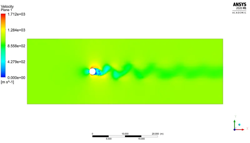
VORTEX SHEDDING BEHIND THE CYLINDER:
ANIMATION VIDEO:
RESIDUAL VELOCTY PLOT:
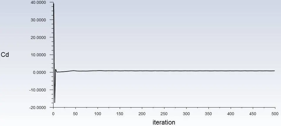
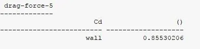
DRAG FORCE PLOT:
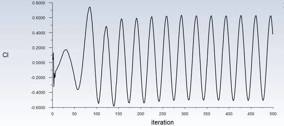
LIFT FORCE PLOT:
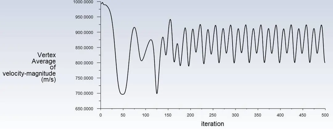
VERTEX AVERAGE OF VELOCITY-MAGNITUDE PLOT:
6.For Transient case
Re=100,`rho=1(kg)/m^3`,Dia=2m,`mu=0.02(kg)/(ms)`
v=1m/s
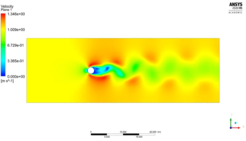
VORTEX SHEDDING BEHIND THE CYLINDER:
ANIMATION VIDEO:
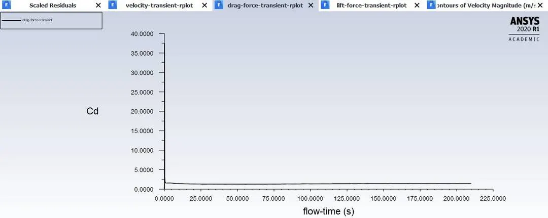
DRAG FORCE PLOT:
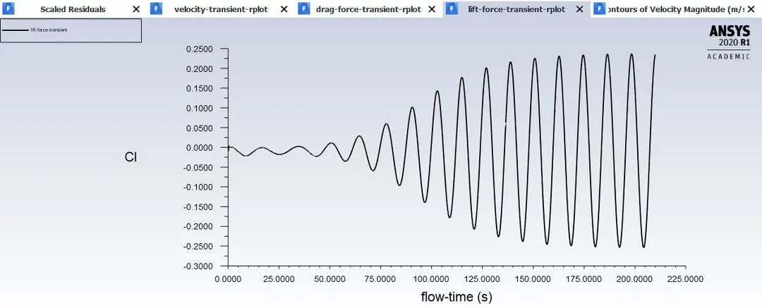
LIFT FORCE PLOT:
VERTEX AVERAGE OF VELOCITY-MAGNITUDE PLOT:
COMPARISION TABLE OF REYNOLDS NUMBER AND ITS DRAG CO-EFFEICIENT:
| Re | velocity | `y^+` | `C_d` |
| 10 | 0.1 | 0.1 | 3.36 |
| 100 | 1 | 0.1 | 1.33 |
| 1000 | 10 | 3 | 1.13 |
| 10000 | 100 | 3 | 1.005 |
| 100000 | 1000 | 3 | 0.855 |
| 100(Transient) | 1 | 3 | 1.36 |
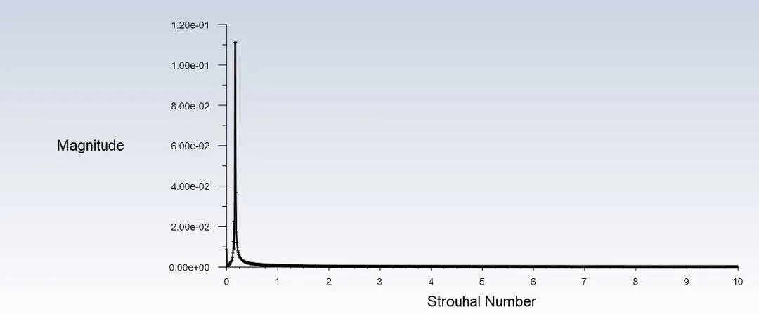
For the unsteady case calculate the Strouhal Number for Re= 100.
`St = (fL)/u`
Where f=frequency,
L=length of cylinder,
u=velocity in m/s
f=No. of iteration cycles/difference between intervals
`f=(2/25)=0.08`
`st=(0.08*2)/1=0.16`
Strouhal number=0.16
CONCLUSION:
Preferred material for this challenge is fluid air which its constant denity of 1`(kg)/m^3` and constant viscocity of 0.02`(kg)/(ms)`.
When Re=10,vortex shedding is not visible,because velocity is constant behind the cylinder and from Re=100, vortex shedding starts generating and increase in Re visible i.e.,velocty increases Re increases.
Therfore here the velocity increases,then the magnitude of drag forces decreases on the basis of the solid object in fluid path.
Steady state simulations are time independent while Transient state simulations are time dependent.
Thus the simulations of the flow over cylinder with steady and unsteady case and coefficients of drag and lift over a cylinder by setting the various Reynolds number are done.
Strouhal number for Re=100 is 0.16.