Steady State Modeling of Species Transport & Gaseous Combustion
Aim:
The main objective of the project is to set up a Steady State Modelling simulation Species Transport and Gaseous Combustion of Natural Gas using Ansys Fluent.
The Objective is further subdivided into two parts:
- Combustion simulation on the combustor model and Analysing the variation of the mass fraction of the different species in the simulation using line probes at different locations of the combustor for CO2, H2O, CH4, N2, O2, NOx emissions & Soot formation.
- Effect of adding the water content in the fuel from 5% to 30% by mole and observe the effect of it on the results.
Introduction
In this Project the generalized eddy-dissipation model to analyze the methane-air combustion system. The combustion will be modelled using a global one-step reaction mechanism, assuming complete conversion of the fuel to `CO_2` and `H_2O`.
The reaction equation is:
`CH_4 + 2O_2-> CO_2+2H_2O`
This reaction will be defined in terms of stoichiometric coefficients, formation enthalpies, and parameters that control the reaction rate. The reaction rate will be determined assuming that turbulent mixing is the rate-limiting process, with the turbulence-chemistry interaction modelled using the eddy-dissipation model.
1.Geometry Creation:
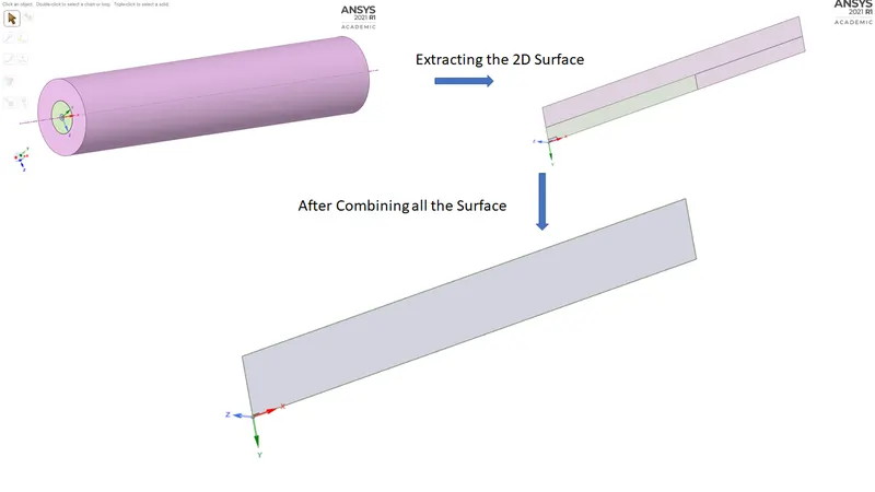
The Combustion Chamber Geometry was designed using a separate cad package using Solidworks. Then the geometry was imported to Ansys design modular for future control volume creation as it defines the fluid flow domain, The 2D geometry was obtained from 3D geometry using Design Modular by creating planes and splitting the part followed by removing the parts.

2. Boundary Creation and Meshing
After the control volumes are perfectly created the boundary tags were created in order to assign the different boundary conditions ie. velocity, temperature(if needed), or some other physics. For this geometry, 3 different boundary tags or names were created that were used earlier to assign the boundary condition. The 6 names are Air Inlet, Fuel Inlet, Axis, Side Walls, Outlet, Walls and Side Walls.
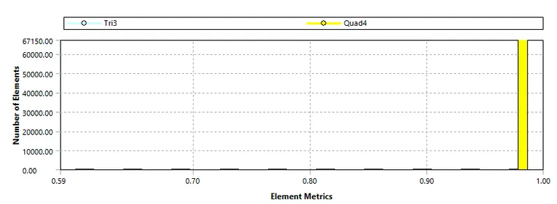
Mesh was generated using Quad shape elements, in order to make it more refine the body sizing method for chosen for each named selection.
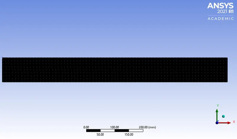
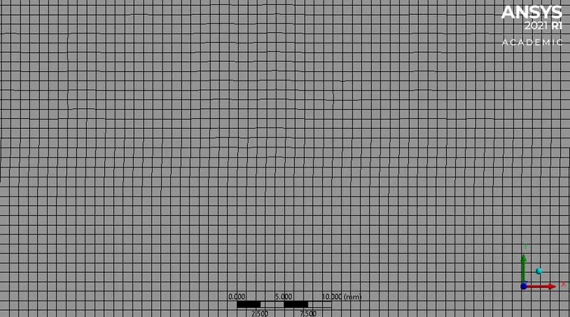
Base Mesh Size is 1mm
| Number of Nodes | 68327 |
| Number of Elements | 67423 |
3. Case Study Setup
For setting up the case study Ansys Fluent was used in order to simulate the case study. The axisymmetric option was enabled
The various parameter was considered while setup this case study. The case study setup dock was used to set up the problem which appears on the left-hand side of the Fluent studio
Solver type: Pressure Based Steady State State simulation
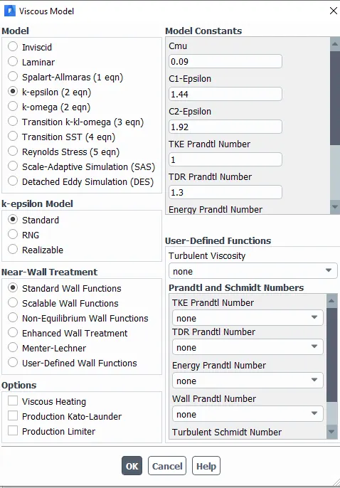
K-Epsilon Standard with Standard Wall treated Viscous model was selected for this problem.
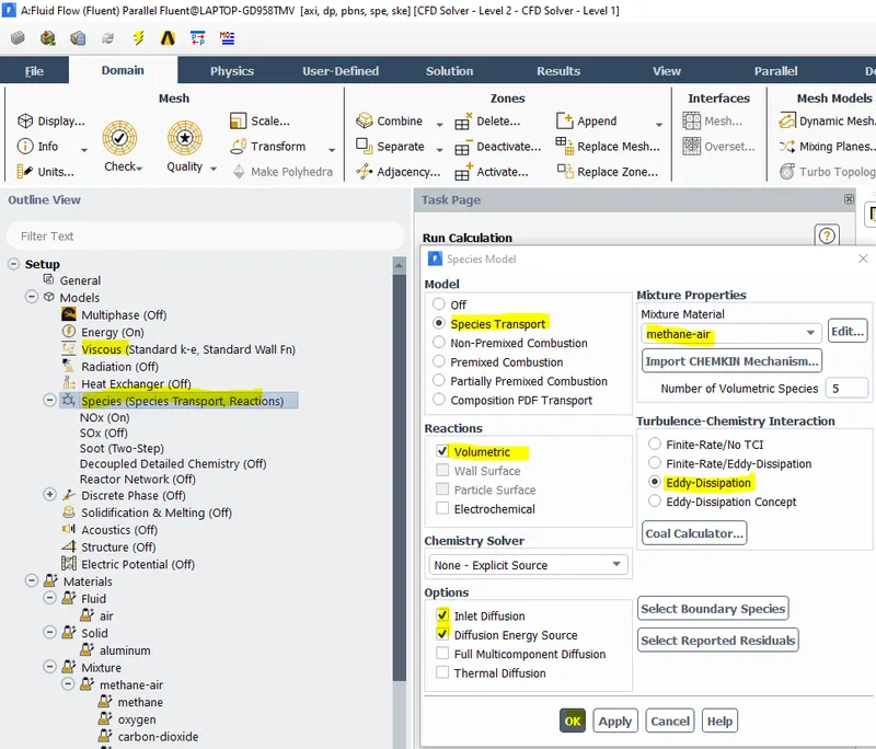
For the combustion problem Species was coupled. The model chosen was "Species Transport" with a volumetric reaction mechanism. The mixture was Methane-Air with Eddy Dissipation
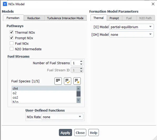
To capture the NO Mass fraction following parameter were setup:
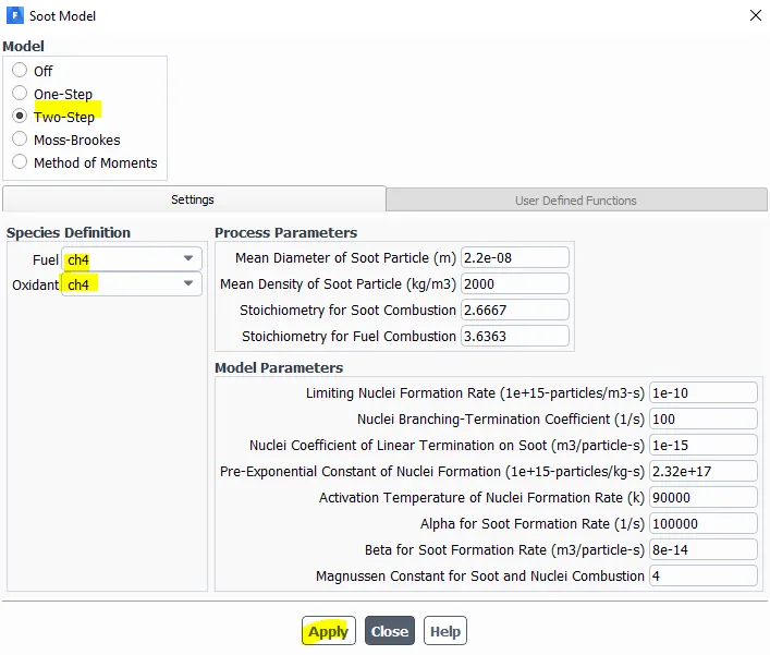
For shoot Formation following setting were made
| S.No. | |||
| 1 | Models |
Viscous Model-K-Epsilon Standard with Standard Wall |
Viscous was Coupled with a Species model |
| 2 | Material |
Methane Air Mixture |
|
| 4 | Boundary Conditions | Inlet- Velocity Type | For assigning the fluid flow air and fuel Velocity |
| Outlet - Pressure Outlet-Escape | Zero gauge Pressure Outlet |
4. Solution
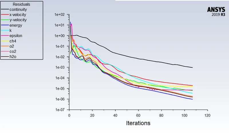
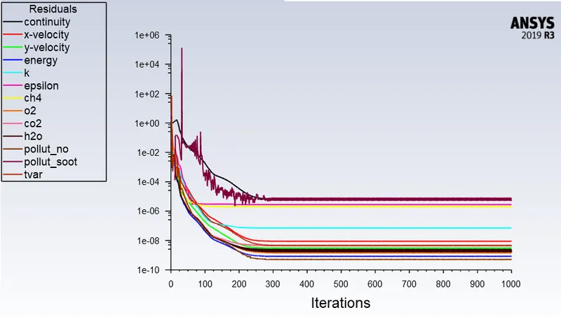
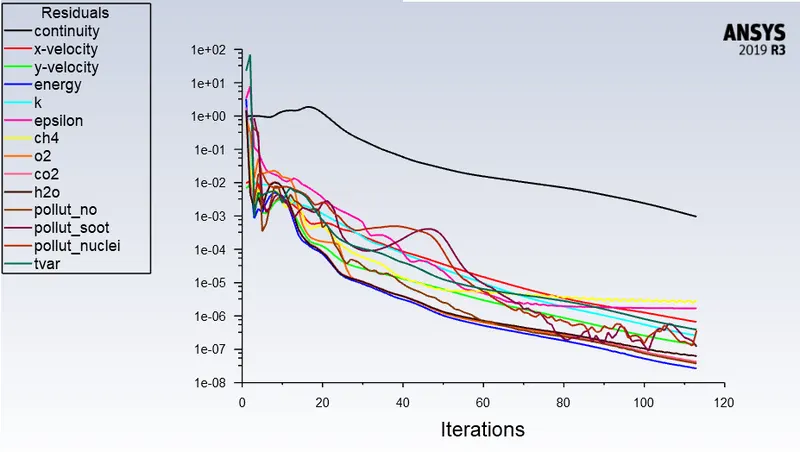
For the Solution Residuals Monitor, the Magnitude was changed to 1e-6 to get more accuracy.
Hybrid Intilizization was used in order to initialize this simulation.
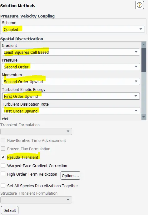
To achieve more fast and accurate converge this parameter or schemes were selected
As this was a Steady State Simulation so the Fixed Simulation was run for 1000 Iterations and the results were generated easily.

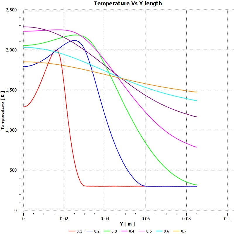
Different data information was presented using how the content and properties change with different z positions
####################################################################################
Case Study 1:
Residual Plot
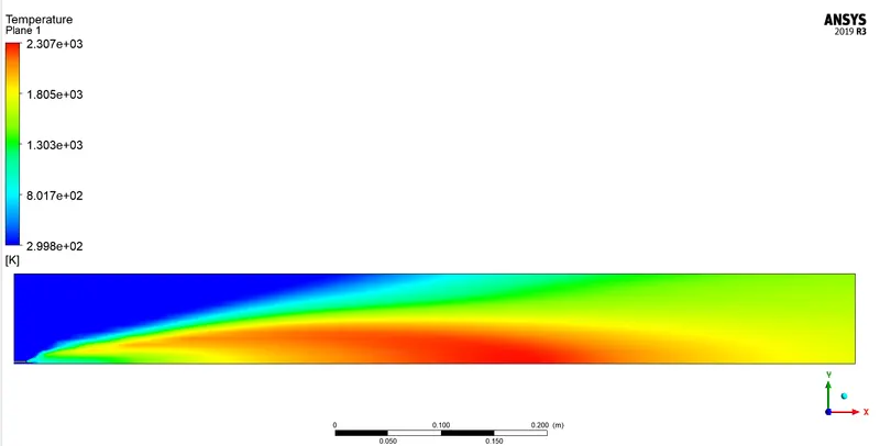
Temperature Contour
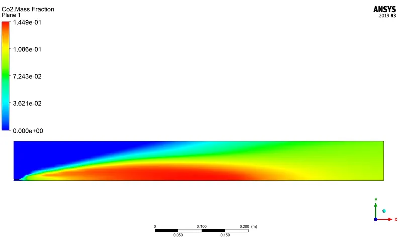
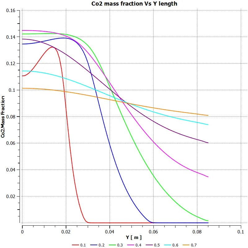
`Co_2` Mass Fraction Contour
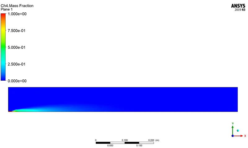
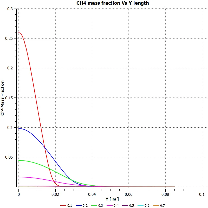
`CH_4` Mass Fraction Contour
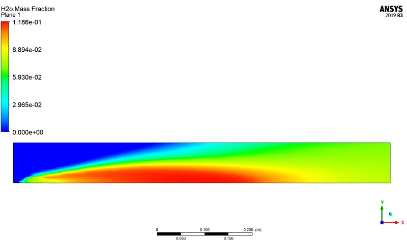
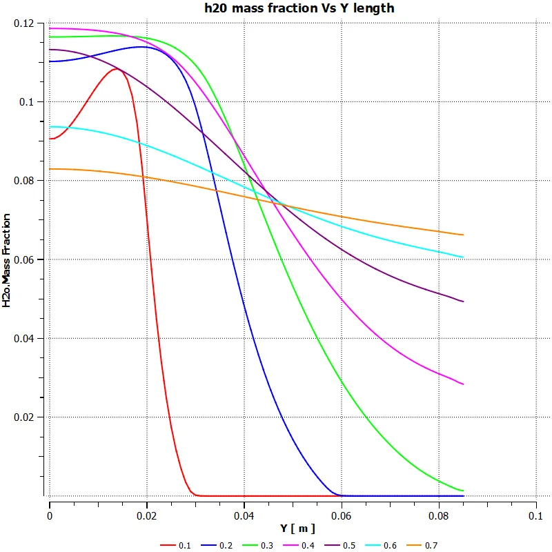
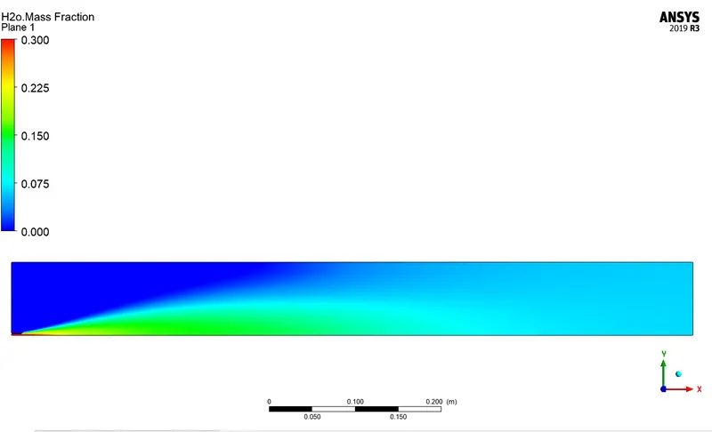
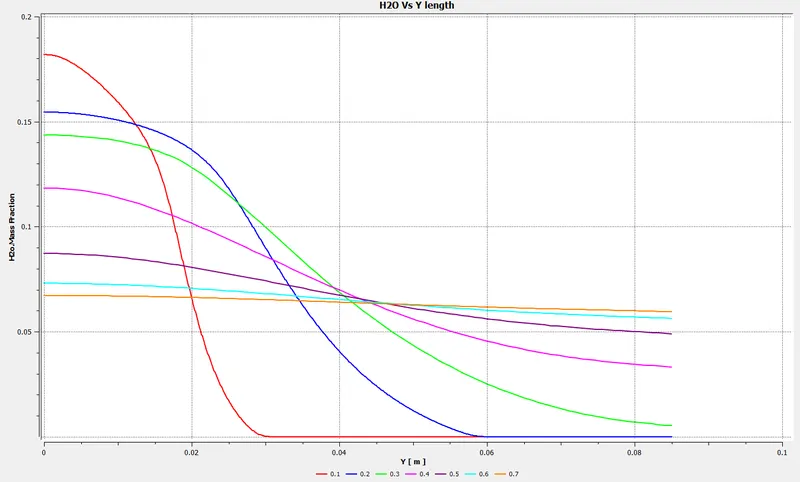
`H_2O` Mass Fraction Contour
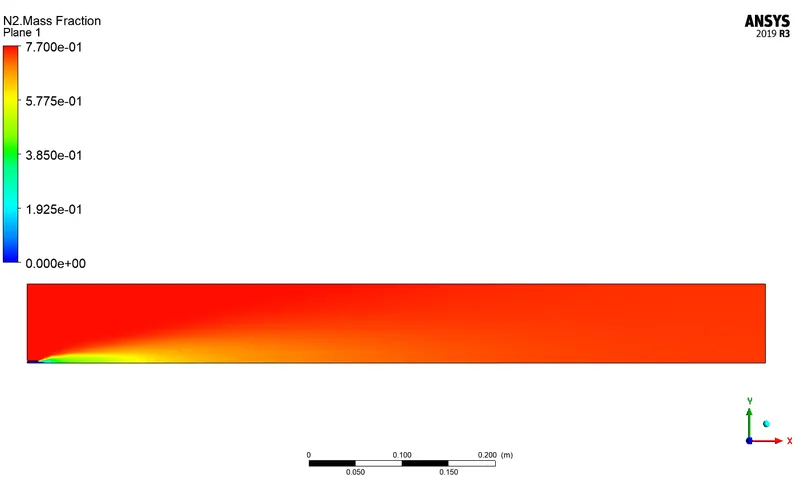
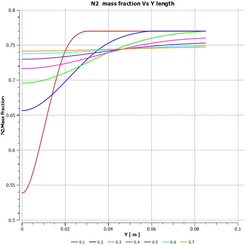
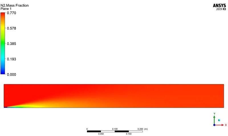
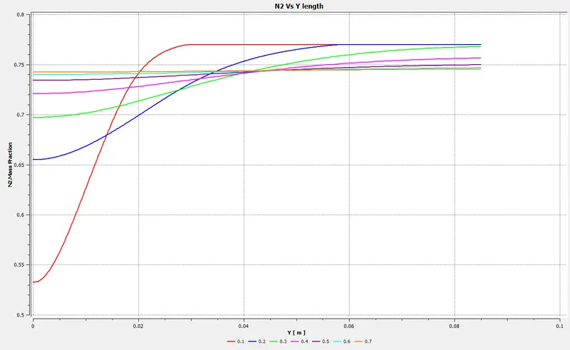
`N_2` Mass Fraction Contour
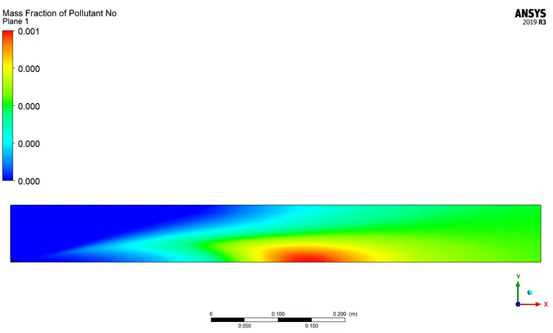
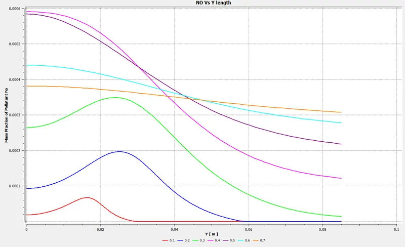
`NO` Mass Fraction Contour
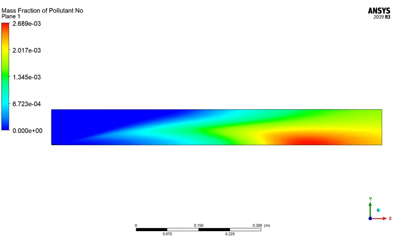
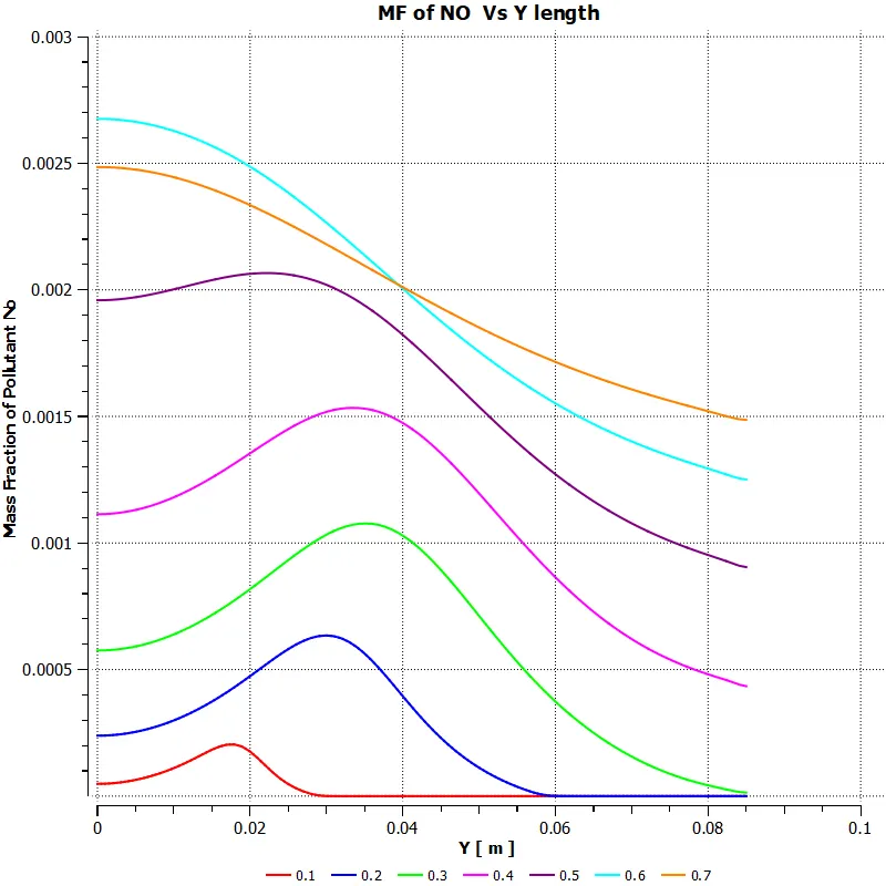
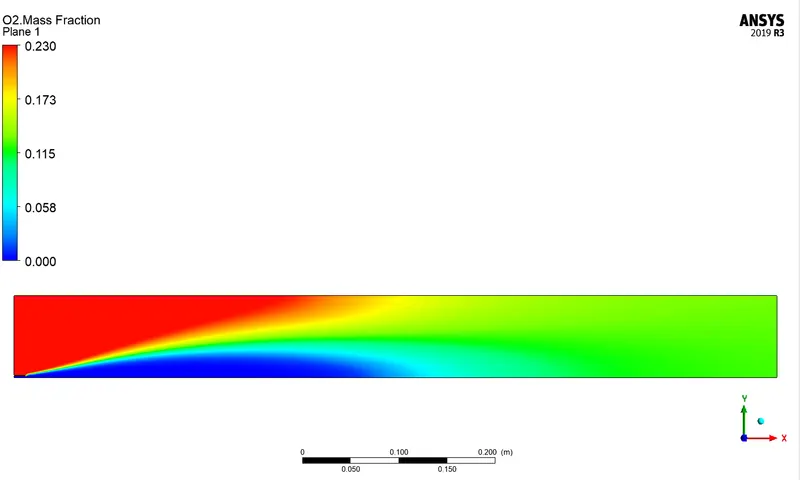
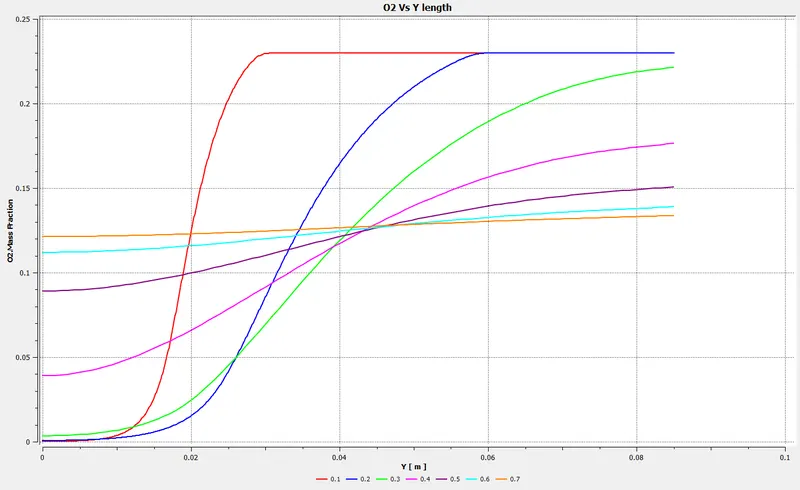
`O_2` Mass Fraction Contour
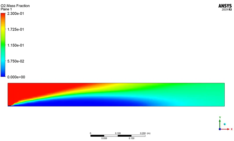
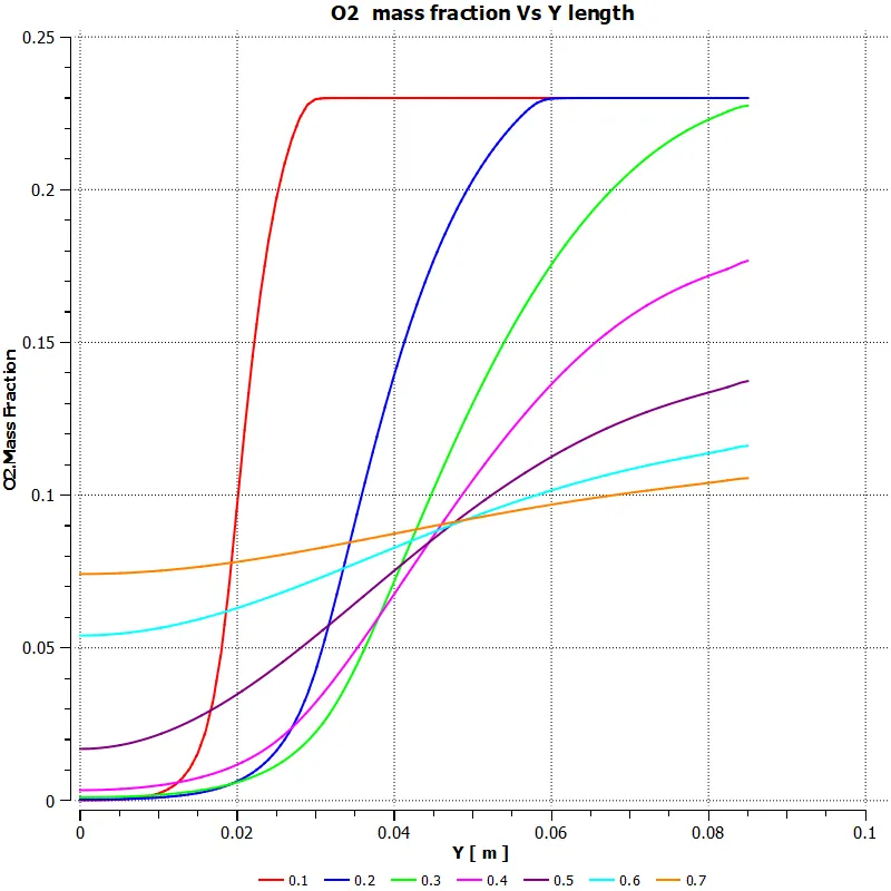
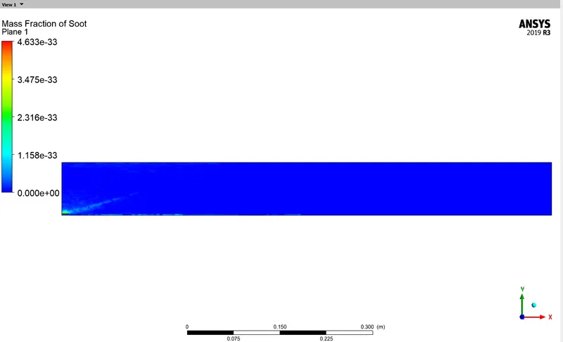
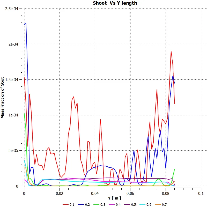
Shoot Formation
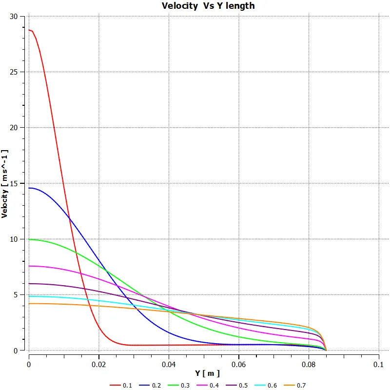
Velocity Plot
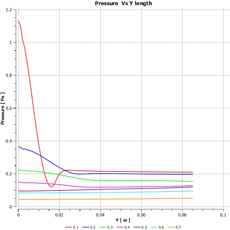
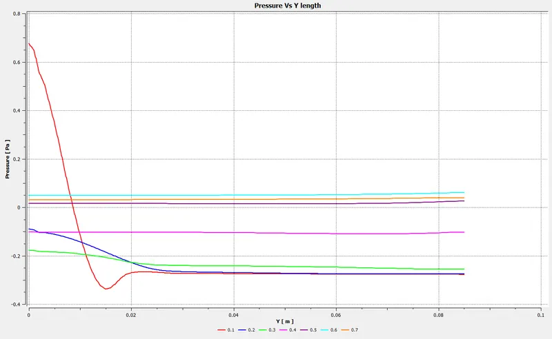
Pressure Plot
Case Study:2
Residual Plot
Temperature Contour
`Co_2` Mass Fraction Contour
`CH_4` Mass Fraction Contour
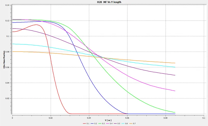
`H_2O` Mass Fraction Contour
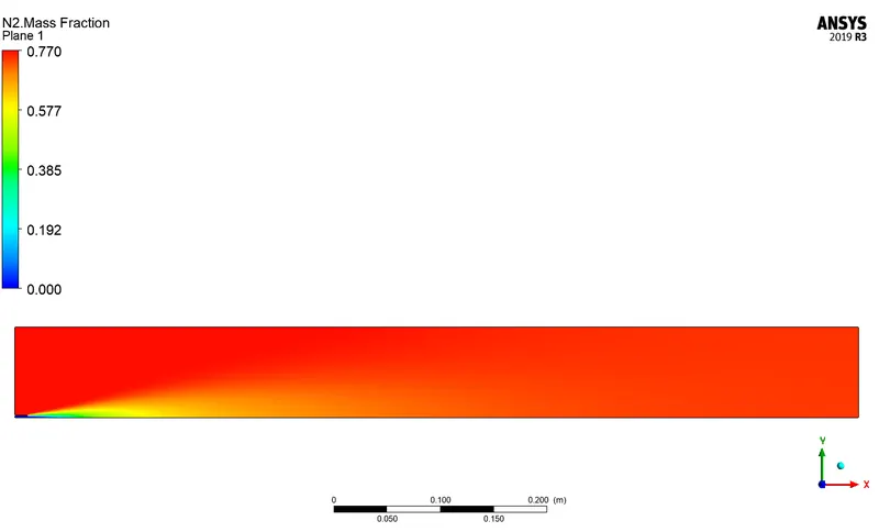
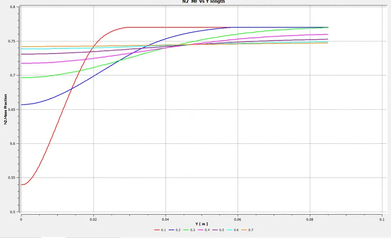
`N_2` Mass Fraction Contour
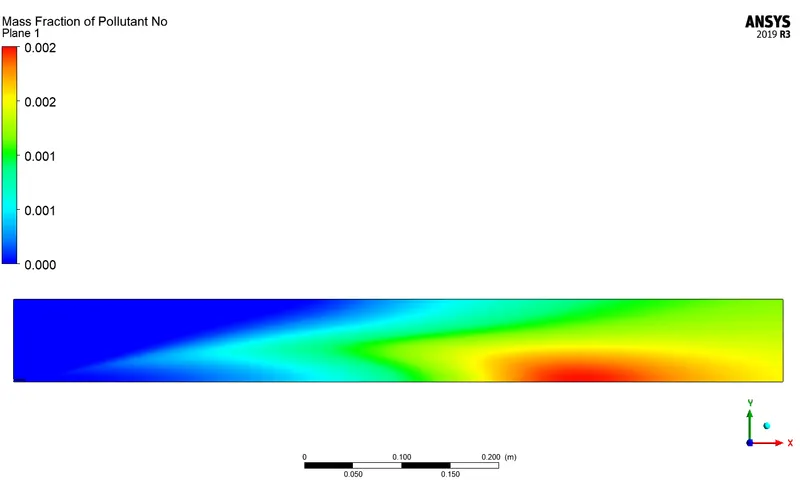
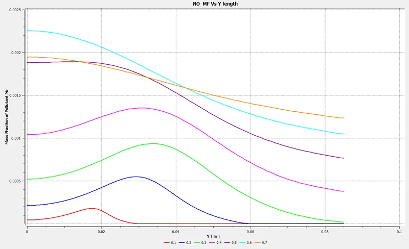
`NO` Mass Fraction Contour
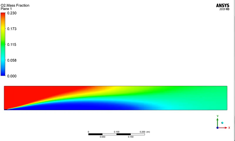
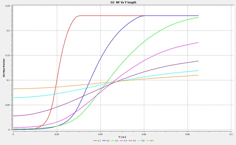
`O_2` Mass Fraction Contour
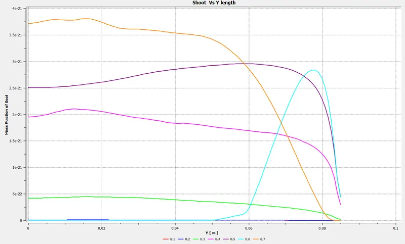
Shoot Formation
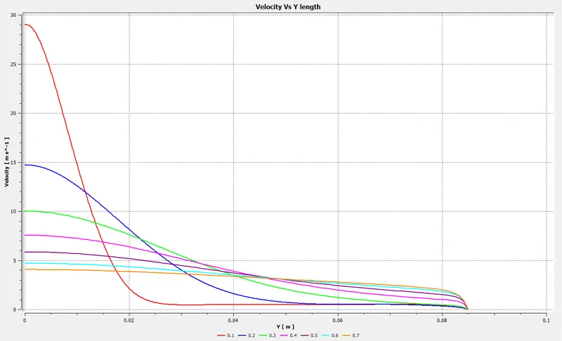
Velocity Plot
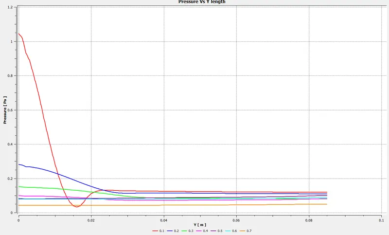
Pressure Plot
Case Study :3
Residual Plot
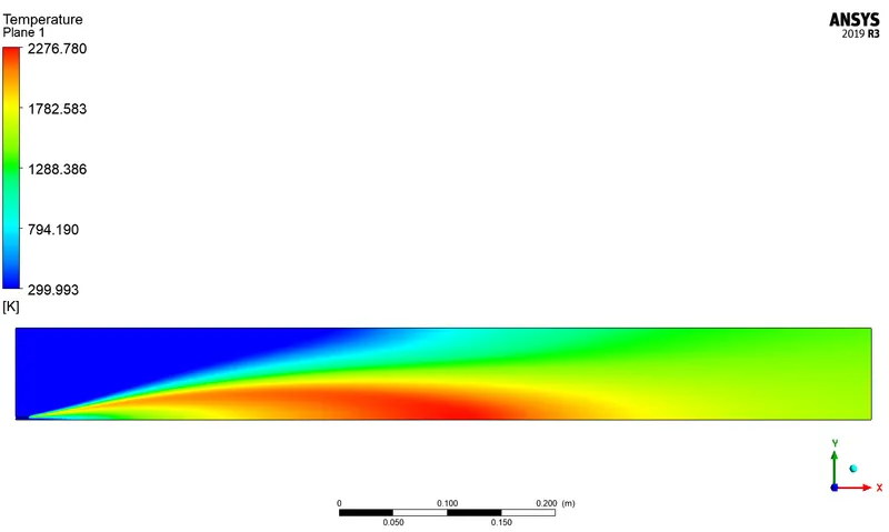
Temperature Contour
`Co_2` Mass Fraction Contour
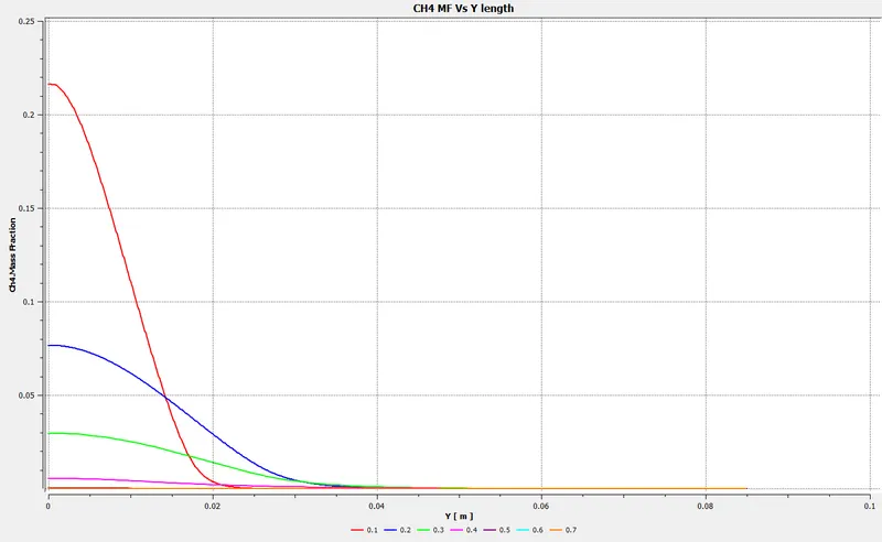
`CH_4` Mass Fraction Contour
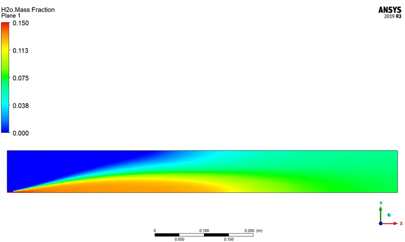
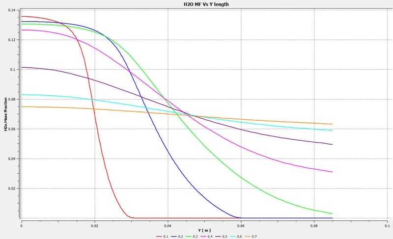
`H_2O` Mass Fraction Contour
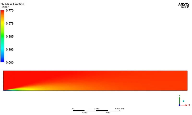
`N_2` Mass Fraction Contour
`NO` Mass Fraction Contour
`O_2` Mass Fraction Contour
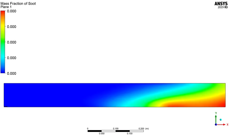
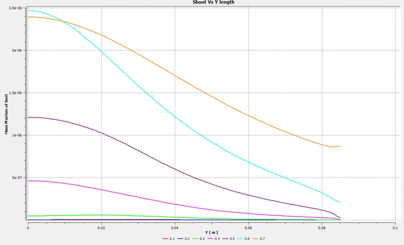
Shoot Formation
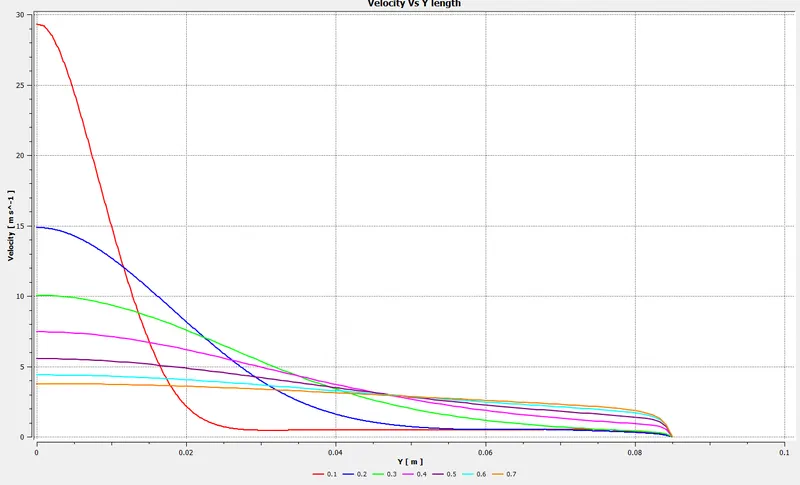
Velocity Plot
Pressure Plot
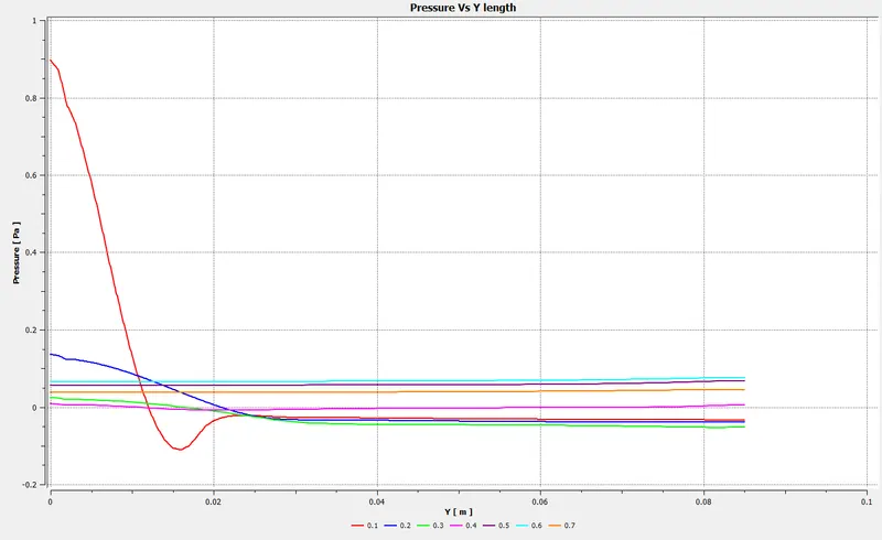
Case Study :4
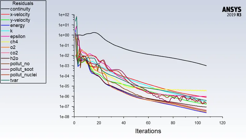
Residual Plot
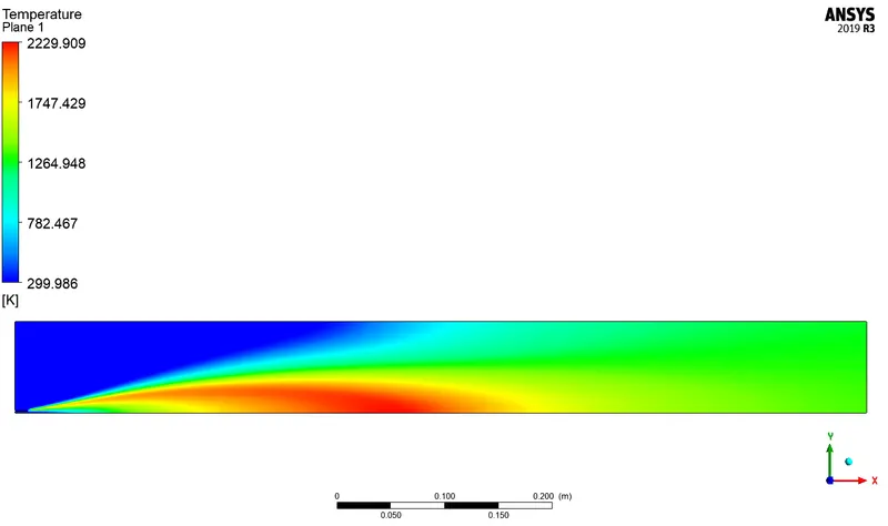
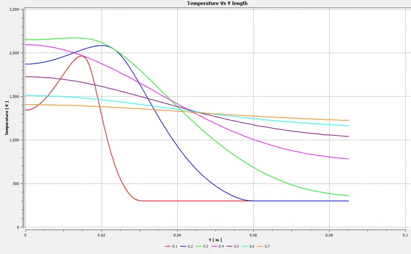
Temperature Contour
`Co_2` Mass Fraction Contour
`CH_4` Mass Fraction Contour
`H_2O` Mass Fraction Contour
`N_2` Mass Fraction Contour
`NO` Mass Fraction Contour
`O_2` Mass Fraction Contour
Shoot Formation
Velocity Plot
Pressure Plot
Conclusion
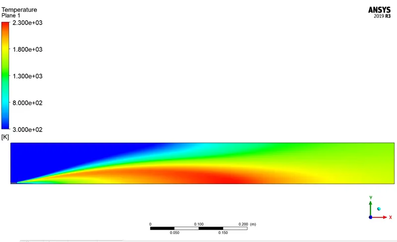
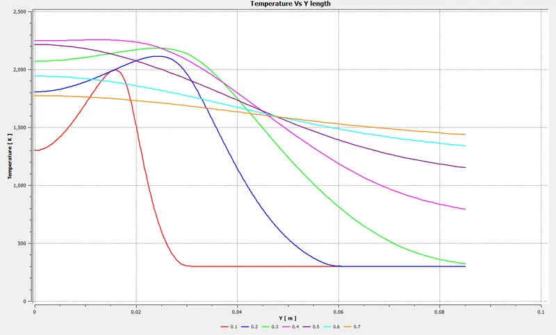
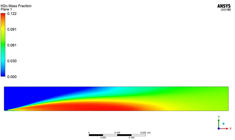
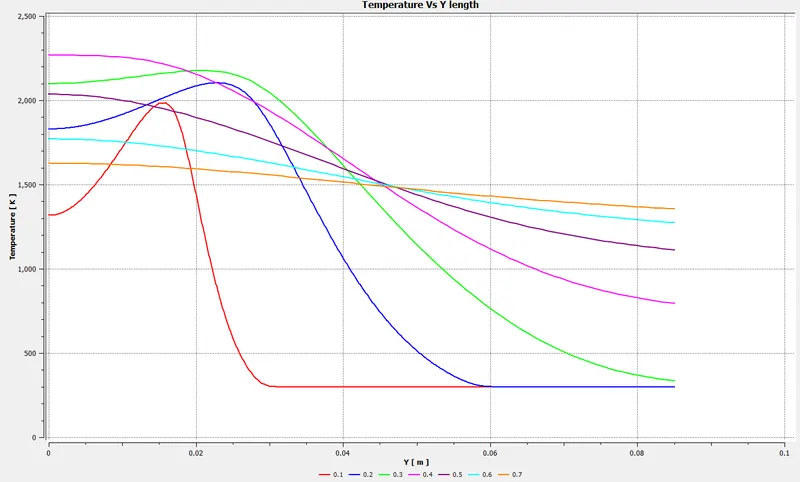
From the Temperature contour and plot, it can be concluded that as the water content is increased with the methane mixture the temperature decreases. When no water was present the maximum temperature was found to be 2307K. When the H2O was introduced in the chamber for 5%, 15% and 30% the maximum temperature was found to be 2300K, 2276K and 2229K respectively. The maximum temperature was found to be at the centre near to axis of rotation of the chamber.
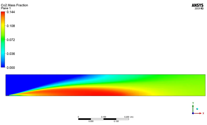
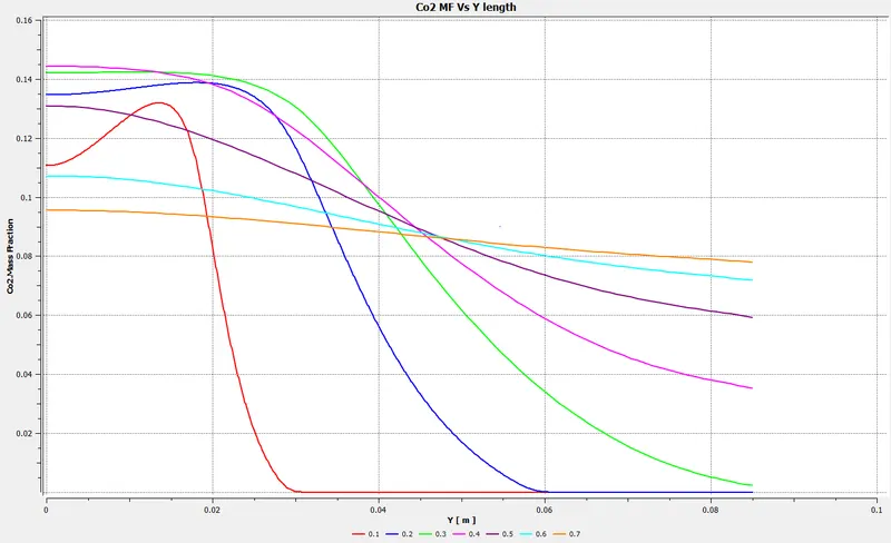
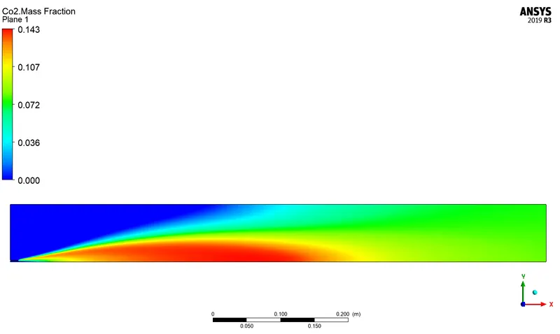
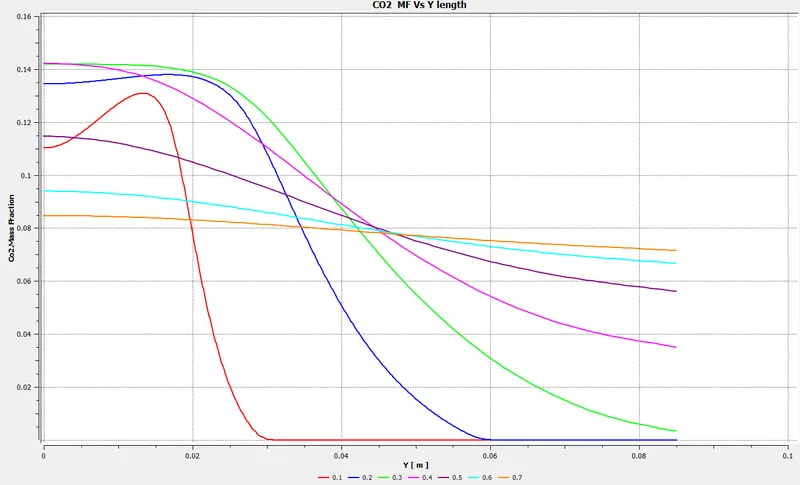
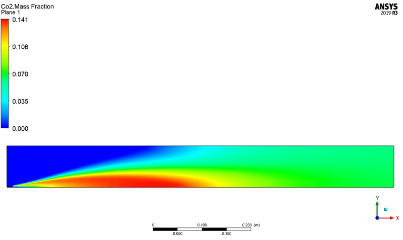
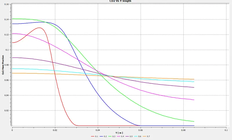
From the CO2 contour and plots, it can be concluded that as the water content was increases or the methane level is reduced to some percent then the formation of CO2 is also reduced by very amount. It can be concluded that when no water was added the Mass fraction was found to be around 0.1449 but whereas when the mole fraction of H2O was increases to 5%, 15% and 30% then the mass fraction was found to be 0.144, 0.143 and 0.141 respectively. At Outlet, the Mass fraction was found to be 0.078, 0.076 and 0.06 for 5%, 15% and 30% respectively.
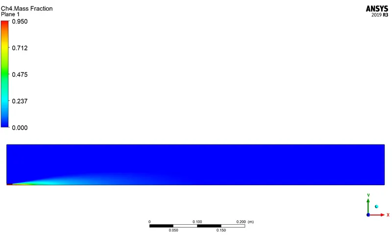
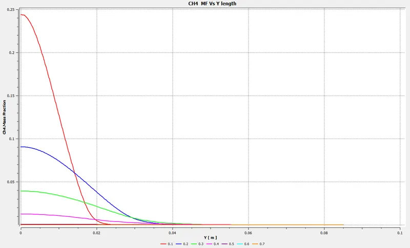
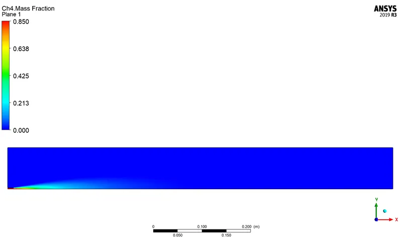
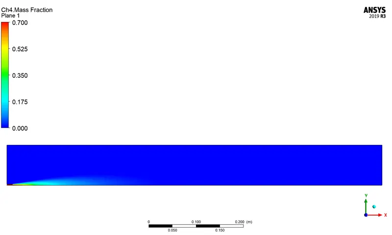
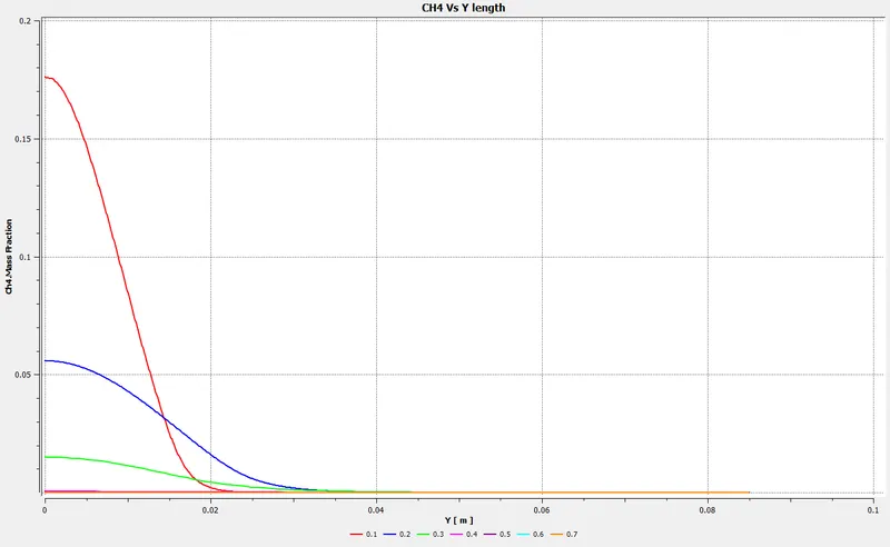
From the CH4 contour and plots, it can be concluded that as the water content was increases or the methane level is reduced to some percent then the formation of CO2 is also reduced by very amount. It can be concluded that when no water was added the Mass fraction was found to be around 0.1449 but whereas when the mole fraction of H2O was increases to 5%, 15% and 30% then the mass fraction was found to be 0.95, 0.85 and 0.70 respectively. At Outlet, the Mass fraction was found to be almost 0 for 5%, 15% and 30% respectively. The maximum was found to be very near to the air inlet.
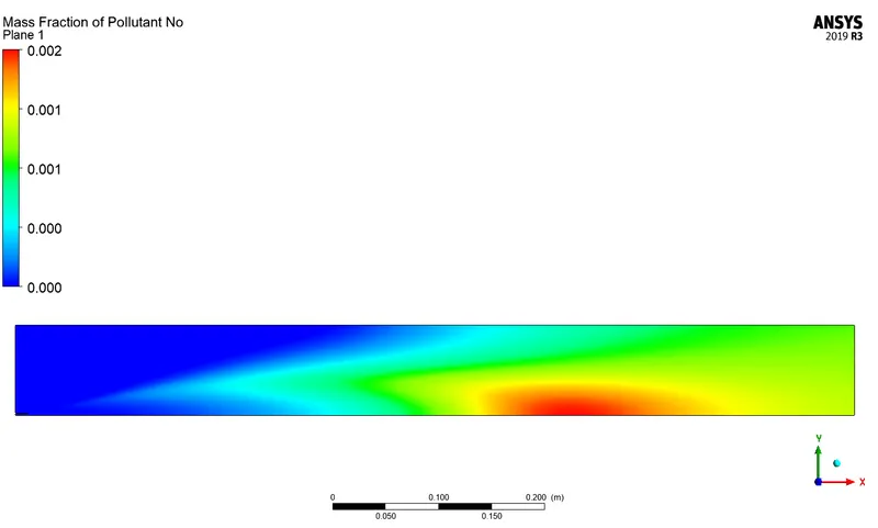
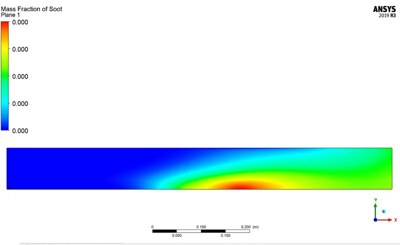
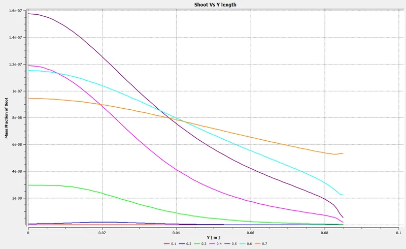
The shoot formed in all the cases, the mass fraction is around zero.
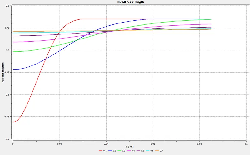
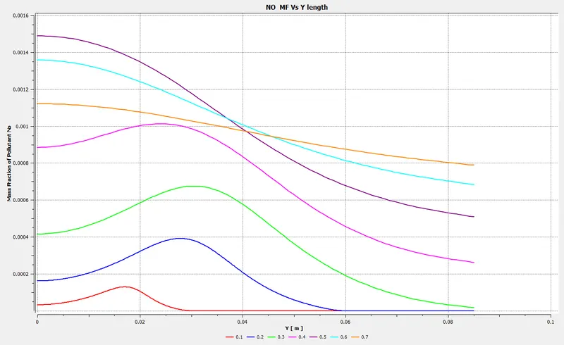
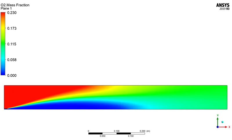
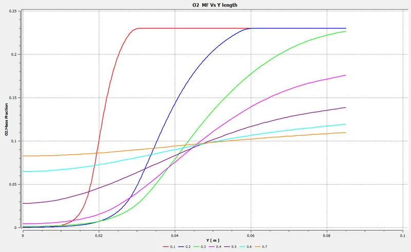
The Maximum O2 N2 and NOx remains almost the same when the content of H2O was increased.
Quick Recap:-
- With increases in the mass fraction of water in the fuel-air mixture, the NOx pollutants are reduced.
- Increases in the mass fraction of water in the fuel-air mixture the Shoot is reduced.
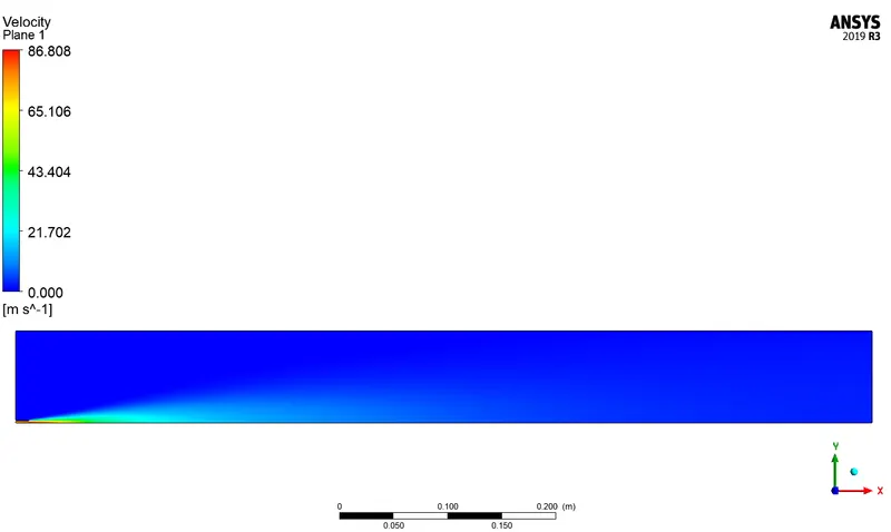
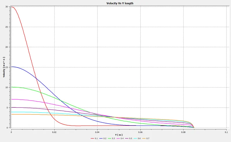
- With increases in the mass fraction of water in the fuel-air mixture, the mixing efficiency and fuel-air are achieved.
- Increases in the mass fraction of water in the fuel-air mixture the temperature at of exhaust gasses are reduced at the outlet