Sketch-Base Features and Dess-Up Feature in Catia.
Objective:- To create a 3D part model using Sketch-Based Features and the Dress-Up Features in CatiaV5 software.
Procedure:-
Open CatiaV5 Software and go to file-New-Part.
Create a point at the center axis with coordinates x=0, y=0, and z=0.
Go to Toolbar-Insert-Sketcher-Positioned sketch.
In Sketcher Positioning select yz-plane and in the projecting point select the center point of the origin.
Sketch the geometry with the Profile toolbar.
Exit the sketch workbench and go to sketch-based Features.
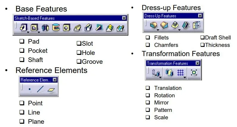
Sketch-Based Features:-
- Pad
- Shaft
- Groove
- Slot
- Hole
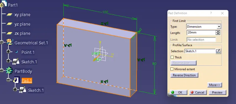
Pad:-
Creating a pad means extruding a profile or a surface in one or two directions. The application lets you choose the limits of creation as well as the direction of extrusion.
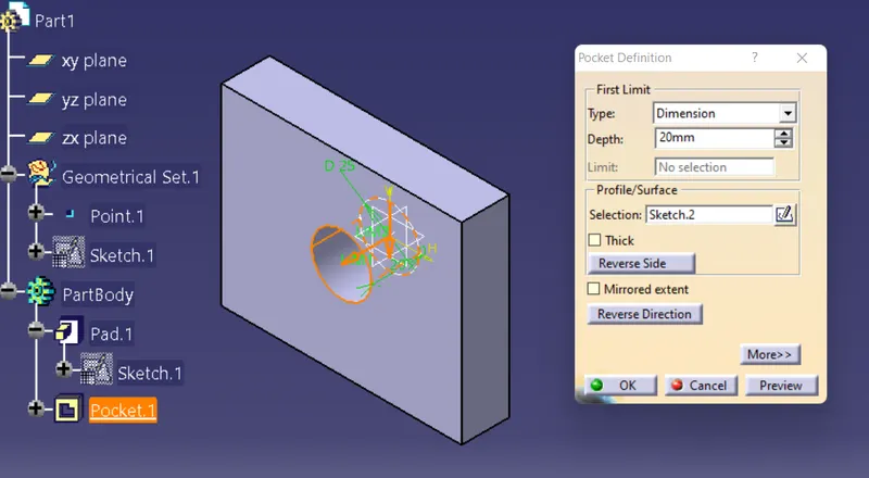
Pocket:-
Creating a pocket involves extruding a profile or a surface and removing the material resulting from the extrusion. The application lets you choose the limits of creation as well as the direction of extrusion. The limits you can use are the same as those available for creating pads.
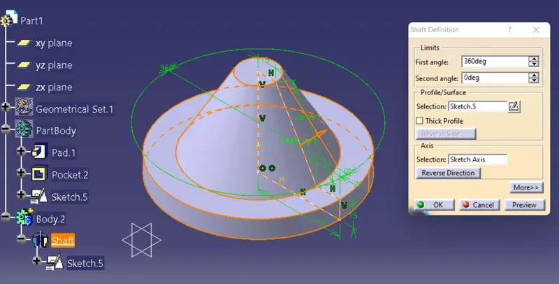
Shaft:-
The shaft is a revolved feature, by using an open profile. We need an open or closed profile and an axis about which the feature will revolve. We can use wireframe geometry as our profile and axes created with the Local Axis capability. We can create shaft form sketches including several closed profiles. these profiles must not intersect and they must be on the same axis.
Groove:-
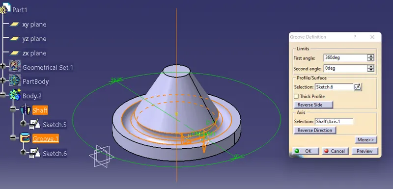
Grooves are revolved features that remove material from existing features. we can create groove form sketches including several closed profiles. This profile must not intersect and they must be on the same side of the axis. If needed, we can change the sketch by clicking the selection field and by selecting another sketch in the geometry or in the specification tree.
Slot:-
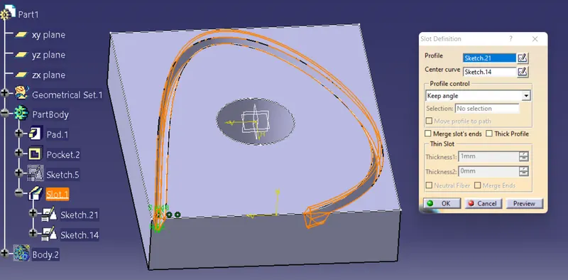
The slot has swept a profile along a center curve to remove material. To define a slot, we need a center curve, a planar profile, a reference element, and optionally a pulling direction. Select the profile, i.e. Sketch. The profile has been designed in a plane normal to the plane used to define the center curve. 3D center curves must be continuous in tangency. If the center curve is planar, it can be discontinuous in tangency. We can use Wireframe geometry as our profile too. In some cases, we need to define whether we need the whole sketch or sub-elements only. Slots can also be created from sketches including several profiles. These profiles must be closed and must not intersect.
Hole:-
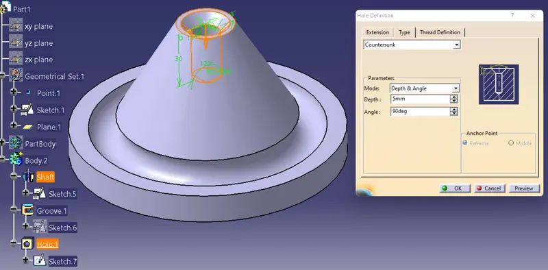
A hole consists in removing material from a body. Various shapes of standard holes can be created. These holes are Simple, Tapered, Counterbored, Countersunk, and Counterdrilled. we can set parameters according to our needs such as Extensions, Tolerancing Dimension, Hole Bottom, Directions, Threads, and Hole types.
Dress-Up Features:-
- Fillet
- Chamfer
- Shell
- Draft
- Thickness
Fillet:-
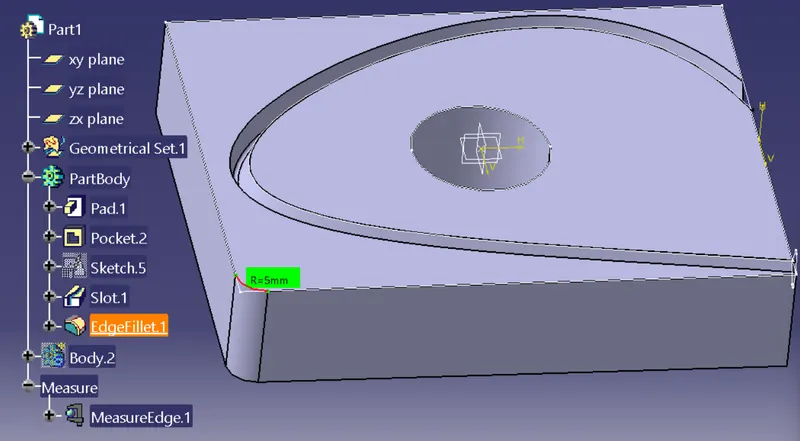
Fillet is a rounding of an interior or exterior corner of a part design. A fillet is a curved face of a constant or variable radius that is tangent to, and that joins two surfaces. Together, these three surfaces form either an inside corner or an outside corner.
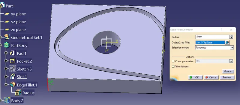
We can measure the angle of fillet radius using the measure items tool in CATIA V5.
Chamfer:-
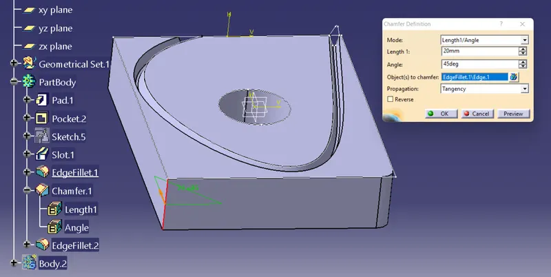
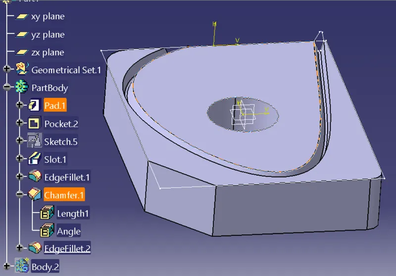
Chamfering consists in removing or adding a flat section from a selected edge to create a beveled surface between the two original faces common to that edge.The default parameters to be defined are Length1 and Angle. We can change this creation mode and set Length1 and Length2 too.
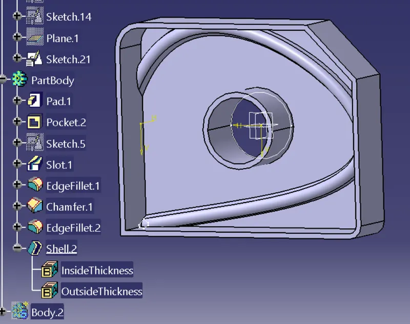
Shell:-
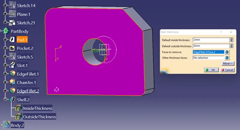
Shelling a feature means emptying it while keeping a given thickness on its sides. Shelling may also consist in adding thickness to the outside. This feature will create a cavity.
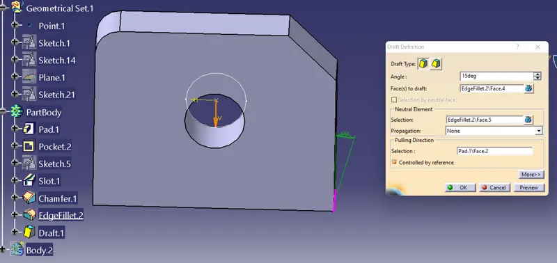
Draft:-
Drafts are defined on molded parts to make them easier to remove from molds. There are two ways of determining the objects to draft: either by explicitly selecting the object or by selecting the neutral element, which makes the application detect the appropriate faces to use.
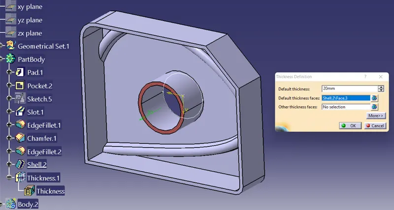
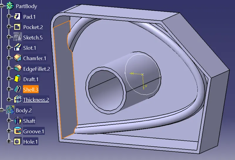
Thickness:-
Sometimes, some thicknesses have to be added or removed before machining the part. This feature will add as well as remove the thickness from the surface.
Conclusion:
Hence, we have studied to create a 3D part modeling using the Sketch-Based Features and the Dress-Up Features.