Sketch a G+1 residential plan according to Vaastu Shastra and Calculation of Loads as per IS code
AIM:
- G+ 1 floor residential plan according Vaastu shastra
-list of structural drawings
-calculation of loads as per IS code
Introduction:
The floor plans serves as the reference for each set of workers on the job. Since it provides details of the layout as well as the scale and dimensions of each room, it becomes easier for the team to measure accurately to ensure that everything is placed where it is supposed to be. Materials for the house can be chosen based on the floor plan.
AASTU SHASTRA- Vaastu shastra is the ancient Indian science of architecture and acts as a guidance to design your home in a way that enhances positive energy. Our nature is abundant with powerhouses of energy sources like the sun, wind, moon, water, earth and fire. Effects of sunrays, flow of winds, pull of earth’s magnetic field and other such cosmic energies. A good home needs to radiate the right kind of energy. A person dwelling in the house comes under the influence of specific energy field which comes under the influence of specific energy field. Architectural changes are not possible for a ready to move in house. Each DIRECTIONS signifies an aspect of life and is governed by various gods as it says.
The basic requirement to be followed for a house project-
- The site should be a square or a rectangle. If possible southwest corner should have 90 degree.
- The main door should be on north, east or northeast side of the plot. 2 gates are preferable, one on east and other in the north. In addition to this northeast, southwest or northwest blocks are also good.
- Ground level should slope towards northeast and levels in southwest should be higher than all other sides.
- A bore well should be provided in north east before the construction takes place.
- More space should be provided in the east and north compared to west and south of the complex.
- Balcony towards north, east and northeast are preferable.
- Kitchen is advisable in south east or northwest but never in northeast.
- Staircase should be provided in the south, west or southwest and should be avoided in northeast because head room of the staircase higher than southwest is not acceptable.
- Underground room or space (cellar) should be kept under the north-eastern or eastern portion of the complex.
- Parking for cars, scooter and bicycles are preferred in northeast cellar.
- Open area in north and south should be used for lawns and sumps.
- AC equipment should be kept in southeast of the complex and should never be installed in northeast under any circumstances.
- Washbasins should be provided in north or east or northeast of the hall.
List of structural drawing for a projects-
CENTRE LINE DRAWING-
- centre line is used for marking the columns position in the ground that is where the excavation is done for footings.
FOOTING AND COLUMN LAYOUT-
- This drawing represents the position and orientation of columns/footing and column/footing reinforcement details.
COLUMN SCHEDULE-
- here you will provide all the details of reinforcement and dimension of all columns .
FOOTING SCHEDULE-
- All the reinforcement details and dimension must be given.
LIFT PIT DRAWING-
- This drawing represents the dimensions, position and section of beam and the reinforcement details of lift pit.
PLINTH BEAM LAYOUT-
- This drawing represents the dimensions, position and section of plinth beams and the details of reinforcement in plinth beam
SLAB DRAWING-
- Here the drawing represents the details of slab
- Slab reinforcement details (note- crank position must be provided and followed on site)
LAYOUT OF FLOORS-
- This drawing represents the dimensions, position and specific reinforcement details of different floors.
LIFT ROOF AND HEAD ROOM DRAWING
- This drawing represents the dimension, reinforcement , position and section of headroom and lift roof in detail.
Complete dead load calculation As per the building design considerations loads are classified into two categories one is gravity loads and another one is lateral loads. The forces or weights which are acts towards the gravitational force are called as gravity loads and the forces or weights which are acts perpendicular to the gravitational force are called as lateral loads.
The dead load, live loads and floor loads are comes under dead loading condition, the seismic; wind loads are comes under the lateral loading condition system. G+1 building structure which is used in the dead load calculation shown in the below figure.
G+1 building structure
ground and first floor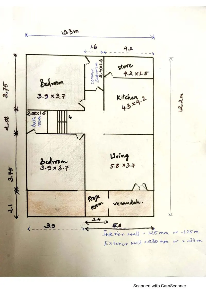
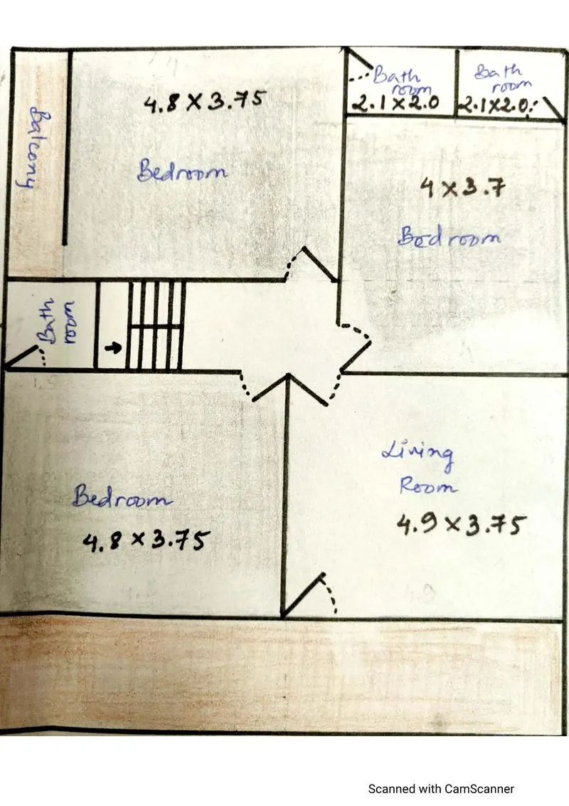
The building is consisting of 2BHK house which is existing in east facing direction.
The following are the specifications considered for the building.
- Beam dimensions : 0.3mX0.45m
- Column dimensions : 0.3mX0.3m
- Slab thickness : 0.125m
- Waist slab thickness : 0.150m
- Height of each floor : 3m
As per IS-875-Part 1 code standards the dead loads are calculated as per the standards of the below specified three factors.
- Static loads (Non movable loads)
- Self weights
- Permanent partitions and immovable fixtures
Static loads in dead load calculation
The static loads are those, in which the dead load values are calculated for non movable members like floors.
Self weight in dead load calculation
Basically for the building structure it will be consisting of beams, columns, slabs, foundation etc. the self weight is the load in which own weight of structural elements which is exists for the specified members. Depends upon the dimensions and specifications of materials the self weight values for structural elements increases or decreases.
Permanent partitions and immovable fixtures
The loads related to the wall loads and immovable objects weights are considered under this case. These are mainly related to the wall loading conditions.
Dead Load
The complete dead load values are classified into the following types
- Self weight loads
- Wall loads
- Stair cases loads
- Self weight in dead load calculation
Self weight of slab = Thickness of the slab (2 slab)X Unit weight of RCC
Unit weight of RCC is 25kN/m^3
= (2(0.125)+0.125)X25
= 6.25kN/m^2.
Beam self weight = Cross section of the beam X Unit weight of RCC
= 0.3X0.45 X25
= 3.375kN/m
Column self weight = Volume of column X height(ground to first) X Unit weight of RCC
= 0.3X0.3X6X25
= 6.725kN
Floor finishers = 50mm thickness(Mortar unit weight=20kN/m^3)
= 0.05X20
= 1kN/m^2
- Wall loads in dead load calculation
Under this case basically wall loads related to the external wall, internal and parapet wall loads are considered and the calculation part of G+1 building is shown in below
External wall load = Thickness of external wall X unit weight of Brick X height of each floor
= 0.23X20X3
(Unit weight of brick is 19-20kN/m^3 )
= 13.8kN/m
Internal wall or patrician wall = Thickness of internal wall X unit weight of Brick X height of each floor
= 0.125X20X3
= 7.5kN/m
Total wall load = Sum of (internal wall load + External wall load + Parapet wall load)
= 13.8+7.5= 21.8 kN/m (here we didn’t add parapet wall)
Live loads:
According to IS code 875 part 2
For residential buildings the given load are as :
- Rooms and kitchens – 2.0 KN/m2
- Toilet and bathrooms-2.0 KN/m2
- Staircase, corridors, store rooms-3.0 KN/m2
- Balconies-3.0 KN/m2
Wind loads:
Not applicable according to IS code 875 part 3 as the building height not exceeds 10 m.
*loads calculation are done as per IS code.