Sketch a G+1 residential plan according to Vaastu Shastra and Calculation of Loads as per IS code
AIM OF THE PROJECT:
- To sketch a G+1 floor residential plan as per Vaastu Shastra.
- To prepare a list of structural drawings to be provided to the construction site.
- To calculate to load acting on the building.
INTRODUCTION:
A house is a residential building. It should be planned as per the resident's taste and requirements. Vaastu shastra plays a major role in the planning, since it creates a good radiant energy, good health and a happiness in a residents's body and mind. An architect creates a plan for the house with consideration of all the above points. After the plan is created, structural engineer designs and provides structural drawing based on the loads acting on the building. And the house is built with an average life of 60 years.
PROCEDURE:
GROUND FLOOR PLAN:
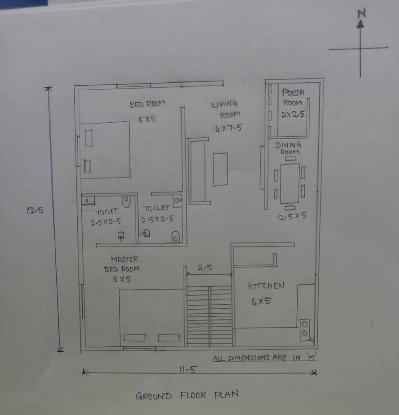
Dimensions of Ground Floor:
Living room - 4 x 7.5
Kitchen - 4 x 5
Dining room - 2.5 x 5
Pooja - 2 x 2.5
Master Bed room - 5 x 5
Bed room - 5 x 5
Toilets - 2.5 x 2.5
Staircase - 2.5 x 3
FIRST FLOOR PLAN:
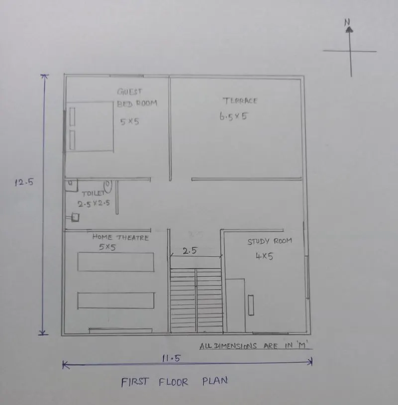
Dimensions of First floor:
Study room - 4 x 5
Home theatre - 5 x 5
Guest Bed room - 5 x 5
Toilet - 2.5 x 2.5
Terrace - 6.5 x 5
Staircase - 2.5 x 3
VAASTU FEATURES IN THE HOUSE:
- Main entrance (Living door entrance) is in the North direction.
- Brahmasthan of the house is cluster free without any obstructions.
- Kitchen is in the South-east direction.
- Kitchen does not share any washroom wall or facing it.
- Master bed room is in the South-west direction.
- Bed is positioned such that head does not rest on North or East.
- Pooja room is placed in the North-east direction and it faces East side.
- In the study room, table is facing East direction and is rectangle in shape.
LIST OF DRAWING TO BE PROVIDED:
- Centerline drawing of the building. It is the first drawing to be released to the site to mark the position of column.
- Footing and column layout drawing. After marking the column position, with the help of the drawing excavation for footing is marked and carried out.
- Underground tank and septic tank layout with reinforcement details.
- Column schedule drawing and footing schedule drawing with reinforcement details.
- Plinth beam layout drawing with reinforcement details.
- First floor beam layout drawing with reinforcement details.
- First floor slab layout drawing with reinforcement details.
- Overhead tank layout with reinforcement details.
- Plumbing and Electrical layout details.
LOAD CALCULATIONS:
Column size - 0.23m x 0.3m
Beam size - 0.23m x 0.3m
Slab thickness - 0.15m
Wall height - 3m
Height of column - Slab thickness + Wall height = 0.15 + 3 = 3.15m
Dead Load:
Total no.of columns - 17
Dead load for column of size 0.23m x 0.3m
Volume of the column = 0.23 * 0.3 * 3.15
= 0.217 m^3
Unit weight of concrete = 25kN/m^3
Dead load of column = Volume of the column * Unit weight of concrete
= 0.217 * 25
= 5.425kN
Total no.of beams - 22 running for 130m
Dead load for beam of size 0.23m x 0.3m
Volume of the beam/m = 0.23 * 0.3
= 0.069 m^2
Unit weight of concrete = 25kN/m^3
Dead load of beam = Volume of the beam * Unit weight of concrete
= 0.069 * 25
= 1.725kN/m
Total area of the slab is 255m^2
Thickness of the slab = 0.15m
Unit of the slab = 25kN/m^3
Self weight of the slab = Thickness of the slab * Unit weight of the slab
= 0.15 * 25
= 3.75kN/m^2
Imposed Load:
As per IS 875 - Part(2) - 1987 from Table 1
Area of staircase and terrace are 47.5m^2
Live load for store room and terrace - 3kN/m^2
Area of other rooms are 240m^2
Live load for other rooms - 2kN/m^2
Wind Load:
As per IS 875 - Part(3) - 2015 from Clause 5.3
Wind load calculation is done for building of height more than 10m.
Here, the wall height itself is 3m. Hence, wind load calculation need not be done.
CODES USED:
- IS 456 - 2000 - For Plain and Reinforced Concrete
- IS 875 (Part 1) - For Dead Load calculations
- Is 875 (Part 2) - For Imposed Load calculations
- IS 875 (Part 3) - For Wind Load Calculations
RESULT:
A plan is created for a G+1 floor residential building as per Vaastu shastra recommendation.
List of drawings that needs to be sent to the construction site for ease mode of work is prepared.
Load calculations for the structural members of the prepared residential building is calculated as per the code and the codes used are also specified.