Sketch a G+1 residential plan according to Vaastu Shastra and Calculation of Loads as per IS code
Aim: Sketch a G+1 plan as per Vastu & Load calculation of structural elements.
Introduction :
- About Vaastu Shastra:
- Vaastu Shastra is the ancient Indian science of architecture and acts as a guideline to design your home in a way that enhances positive energy.
- Our nature is abundant with powerhouses of energy sources like the sun, wind, moon, water, earth and fire.
- Effect of sunrays, the flow of winds, the pull of earth’s magnetic field and other such cosmic energies.
- A good home needs to radiate the right kind of energy.
- A person dwelling in a house comes under the influence of a specific energy field.
- Architectural changes are not possible for a ready-to-move-in house.
- Basic principals:
- Shape:
Rooms should preferably be square or rectangular.
- Room basic:
The room should be airy, well-lit, bright and clean.
- Home centre:
The Centre of the house should be an empty space.
- Stairs and Furniture:
Heavy furniture should be kept in the south-west direction
- Water:
Avoid keeping plants and water features in the bedroom.
- Dining table:
The dining space should be near the kitchen and not near the main door.
- Mirror placement:
Mirror facing the bed is strictly not allowed. Mirrors in the bedroom need to be placed in such a way that the bed cannot be seen.
- About Loads:
A structural load is a force that is applied to the structure for which deformation or twisting may occur in the structure.
- Types of Loads:
- Dead Load:
It is the self-weight of the structural elements that are applied to the structure. This load is calculated by using the IS 875 Part 1 code.
- Live Load:
It is the load that varies with time. This load is not a stable load it varies in different parts of the structure. As the load varies so we cannot calculate it every time for that IS 875 part 2 has given a table from where we can take the load.
- Wind Load:
This is an external load that is applied to the structure by the wind. In this design wind pressure is calculated and it varies with the height of the structure. The design wind pressure is calculated using the IS 875 part 3. As per IS 875 part 3 below the building height of 10m no wind load is calculated.
- Snow Load:
This is also an external load that is caused by the snow. This load is only applicable in the snowfall regions. This load is calculated by using the IS 875 Part4.
- Seismic Load:
This is an external load applied to the structure and caused by the earthquake. This depends on the zones that are given in the IS 1893 part 1.
Procedure:
- The list of drawings that is mandatory to be provided to the sites are:
- Title and Legend Sheet.
- Architectural Drawing:
- Setting out Plan.
- Centerline Plans.
- Floor Plans with dimensions and centerline marking.
- Section and details.
- Elevations and Finish Details.
- Structural Drawing:
- Centre line drawing.
- Footing and Column layout with reinforcement details.
- Column Schedule with reinforcement details.
- Plinth beam layout with reinforcement details.
- First-floor beam layout with reinforcement details.
- First-floor slab layout with reinforcement details.
- Lift pit and headroom reinforcement details.
- Consultant Drawings:
- Mechanical Drawing.
- Electrical Drawing.
- Plumbing Drawing.
- Fire and Safety Drawing.
- Floor Plans:
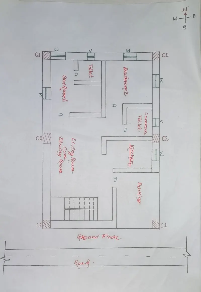
Calculations:
Dead Load Calculation:
1. Columns:
Given Data: For C1
L= 0.3 m, B=0.3 m, H=4.5m
Now,
The total volume of concrete= L x B x H = (0.3 x 0.3 x 4.5) = 0.405 m^3
The unit weight of RCC concrete is = 25 KN/m^3.
A dead load of column C1 = Unit Weight x Volume of concrete = 25 x 0.405 = 10.125 KN.
Given Data: For C2
L= 0.3 m, B=0.45 m, H=4.5m
Now,
The total volume of concrete= L x B x H = (0.3 x 0.45 x 4.5) = 0.6075 m^3
The unit weight of RCC concrete is = 25 KN/m^3.
A dead load of column C1 = Unit Weight x Volume of concrete = 25 x 0.6075 = 15.1875 KN.
2. Beams:
Given Data:
L= 1 m (Considering), B=0.3 m, D=0.45m
Now,
The total volume of concrete= L x B x H = (1 x 0.3 x 0.45) = 0.135 m^3
The unit weight of RCC concrete is = 25 KN/m^3.
A dead load of beam = Unit Weight x Volume of concrete = 25 x 0.135 = 3.375 KN/m.
3. Slabs:
Given Data:
L= 1 m, B= 1 m, T= 125mm i.e, = 0.125 m
Now,
The total volume of concrete= L x B x H = (1x 1 x 0.125) = 0.125m^3
The unit weight of RCC concrete is = 25 KN/m^3.
A dead load of Slab= Unit Weight x Volume of concrete = 25x 0.125= 3.125KN/m^2.
4. Brick Wall:
Given Data:
Height of the wall = 4.5 m
The thickness of the external wall = 230 mm i.e, = 0.23 m
Unit weight of the brick wall/ brick masonry = 20 KN/m^3.
A dead load for the external wall = Unit weight x Wall Thickness x Wall height = 20 x 4.5 x 0.23
= 20.7 KN/m.
Given Data:
Height of the wall = 4.5 m
The thickness of the internal wall = 150 mm i.e, = 0.15 m
Unit weight of the brick wall/ brick masonry = 20 KN/m^3.
A dead load for the internal wall = Unit weight x Wall Thickness x Wall height = 20 x 4.5 x 0.15
= 13.5 KN/m.
Live Load calculation as per IS 875: part 2 (table1):
- Bedroom1: 2KN/m^2
- Bedroom2: 2KN/m^2
- Toilet:2KN/m^2
- Common Toilet:2KN/m^2
- Kitchen:2KN/m^2
- Living/Dining:2KN/m^2
- Study room:2KN/m^2
- Staircase: 3KN/m^2
- Open Terrace:3KN/m^2
Wind Load Calculation:
As per IS 875 part 3 no wind load is considered below the height of 10 m. So, for a 9 m building height no wind load calculation is needed.
Results:
Dead Load:
1. Columns:
For column C1:10.125 KN.
For column C2: 15.1875 KN.
The total dead load of a single column: ( 10.125 + 15.1875 ) = 25.3125 KN.
2. Beams:
A dead load of a beam per unit length: 3.375 KN/m.
3. Slab:
A dead load of a slab per unit area: 3.125KN/m^2.
4. Brick Wall:
For external wall:20.7 KN/m.
For internal wall:13.5 KN/m.
Total dead of wall per unit length: (20.7 + 13.5 ) = 34.2 KN/m.
Live Load:
The live load of each element is taken from the IS 875 part 2 table 1.
Total live load on the structure: (2 + 2 + 2 + 2 + 2 + 2 + 2 + 3 + 3) = 20 KN/m^2.
Wind Load:
There is no wind load as the structure height is below 10m. As per IS 875 part 3 if the structure height is below 10 m then it is not required to calculate wind load.