Sketch a G+1 residential plan according to Vaastu Shastra and Calculation of Loads as per IS code
Name: Zaid Ghanem
Date: 16/3/2022
Course Name: Introduction to Construction Materials and Test on the materials
Answers for Challenge No.10
Introduction& Aim
In this project report, a sketch of a G+1 Residential Plan as Per Vaastu Shastra, alongside listing the drawings which should be handed over to site, and calculating the loads on the structural elements as per IS Code
Task
Sketch a G+1 floor residential plan, according to Vaastu Shastra, and list down the names of the structural drawings required to be provided to the site for construction.
Also, assume the sizes of the structural elements (Column, Beam, Slab, etc.,) and accordingly calculate the individual corresponding loads from the members as per IS code.
G+1 Residential Plan Sketch
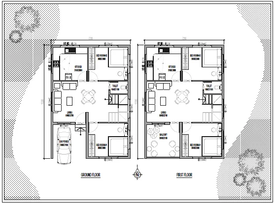
Based on the above sketch, the following load assumptions will be done, as per IS Code
Unit Weight of concrete is 25KN/m3
Unit Weight of masonry wall is 20 KN/m3
Height of wall is 4.5 m
All Columns are at the corners
Column Sizes will be 400x400
Beam Size will be 400x500
Slab thickness to be 250mm
Live Load should be minimum of 2KN/m2 and will be assumed as 2.5 KN/m2
Calculation Procedure
Dead load on Slab is calculated as follows considering the long span (10.3m)
Dead Load= 0.250*10.3*25= 64.375KN/m2
Dead Load of Wall on Beam= 4.5*0.23*20= 20.7 KN/m
Dead Load on Beam = 0.4*0.5*25= 5KN/m+ DL of Slab+ DL of Wall
Dead Load on Beam= 20.7+64.375+5= 90.075 KN/m
Dead Load on Columns= Self Weight of Column+ Dead Load on Beam
Dead Load on Columns= 0.4*0.4*4.5*25+90.075= 108.075 KN
Live Load on Slab should be minimum 2.0 KN/m2, and is considered 2.5KN/m2
Live Load on slab= Live Load on Beam, = 2.5KN/m
Live Load on Column will be= 2.5*10.3 (Considering the Long Span)
Live Load on Column will be= 25.75KN
Since the slab height is less than 10m, Wind Load is not necessary to be calculated, hence, below is the table of Loads on Each Structure
|
Element |
Dead Load |
Live Load |
|
Slab |
64.375 KN/m2 |
2.5 KN/m2 |
|
Walls |
20.7 KN/m |
- |
|
Beams |
90.075 KN/m |
2.5 KN/m |
|
Columns |
108.075 KN |
25.75 KN |
|
Columns At Ground Floor |
216.15 KN |
51.5 KN |
List of Drawings that should be handed to site team are as follows
- Centerline Drawing: it shows the gridline distribution and the dimension between grids to ease the site layout survey works
- Footing and Column Drawings with reinforcement details: it will show the positioning of the footing from the centerline and the respective gridlines, and the column position from the center of the footing
- Column schedule with reinforcement details: it will show the column sizes in each floor, and the placement of reinforcement, the concrete cover requirement from each side
- Plinth Beam Drawing with reinforcement details:
- First Floor beam and slab layout with reinforcement details
- Lift pit and head room reinforcement details