Simulation of Side Pole Crash of Dodge Neon BIW model using Radioss
Aim:
1. To perform side crash for Dodge Neon BIW model by setting it with the following parameters:
1) Checking the unit system and either following [Mg mm s] or [Kg mm ms] unit systems.
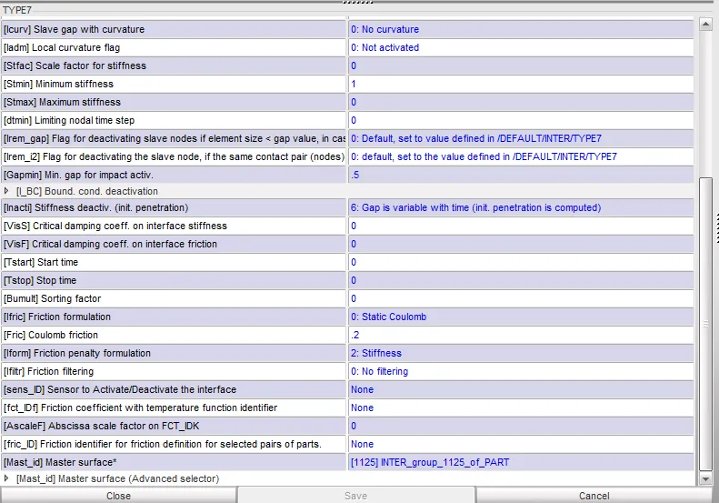
2) Creating appropriate contact interface (Type 7), with friction=0.2 and also inputting other recommended parameters.
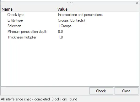
3) Making sure of no penetration and intersections by running the penetration checker and clearing the penetrations and intersections if any.
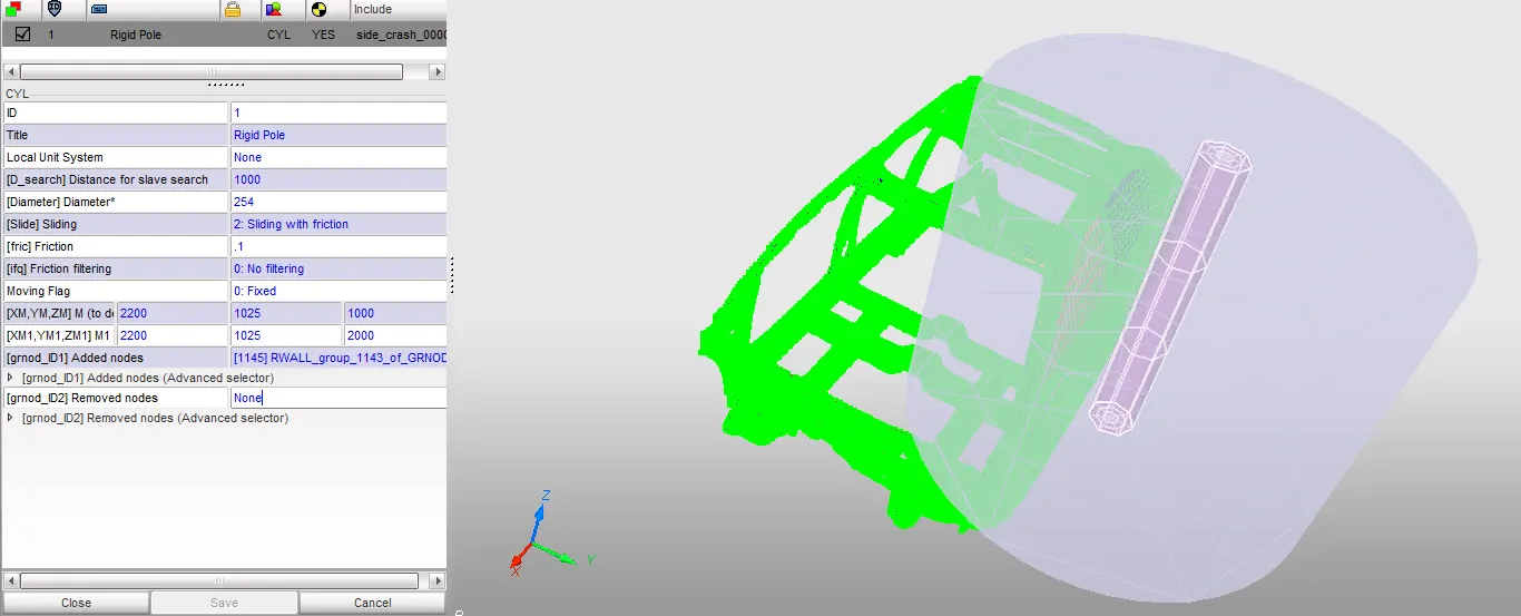
4) Creating a cylindrical rigid wall with sliding friction 0.1 as per reference model or full model.
5) Comparing the model weight with the reference model or full model and using added masses to reach target weight 700kg while getting CG about the required range.
6) Setting up Initial velocity for the model.
7) Running model checker to ensure good quality and clearing errors and warnings if any.
8) Checking the runtime and timestep in the engine and animation cards of the model and inputting the value as 80 ms for runtime and 0.5 to 0.1 microseconds for timestep.
2. After running the simulation getting the following outputs:
1) Obtaining Sectional forces in the cross member.
2) Obtaining Intrusion at B pillar,hinge pillar and fuel tank region and providing recommendation on what can help to reduce Fuel tank intrusion.
3) Obtaining the peak velocity of inner node of the door.
4) Plotting energy curves and noticing any difference.
Theory:
The model given to us is the Dodge Neon BIW model. We have to setup a cylindrical rigid wall and perform the side crash analysis and obtaining the required results after the simulation. The car on running the simulation crashs on to the pole with B pillar side getting hit and damaged. The results obtained based on the impact with side pole.
Procedure:
1. Setting up the model:
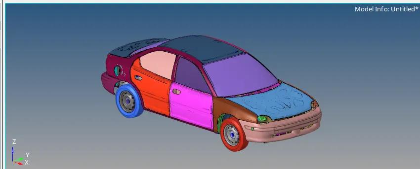
1) In this project we have to take the full car model of the neon dodge car as a reference as shown in the image given below.
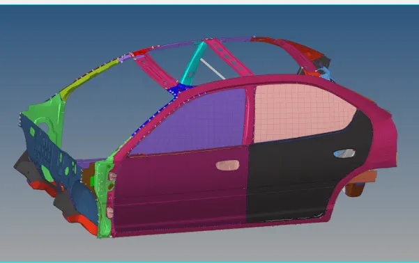
2) We use the reduced model having only BIW components for the side crash analysis as shown in the image given below.
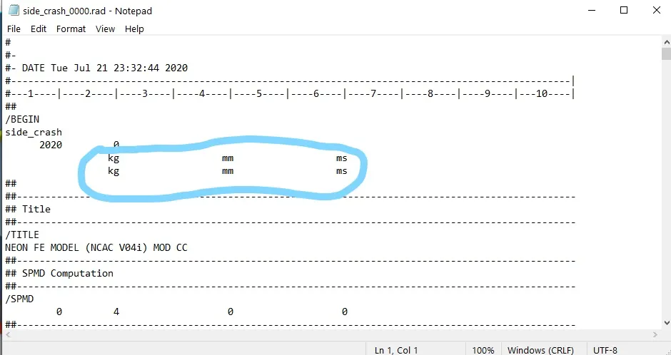
3) We then check the unit system for performing the analysis here, we follow the [Kg mm ms] unit system as shown in the image given below.
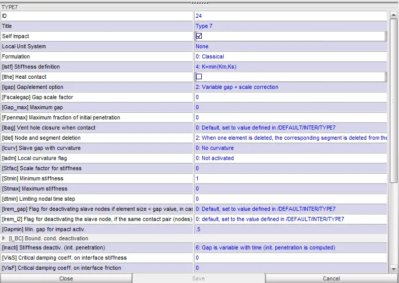
4) We then, create a type 7 contact interface with the friction= 0.2 and we also input other recommended parameters as shown in the image given below.
5) We then run the penetration checker to find out if there are any penetrations or intersections in the model, we run the checker for elements groups(contacts) and components. The results show 0 penetrations and intersections as shown in the image given below.
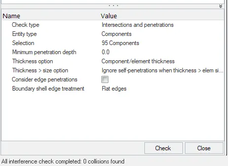
6) We create a cylindrical rigid wall with diameter 254 mm according to FMVSS standards with sliding friction after impact as 0.1 and search distance of 1000 as shown in the image given below.
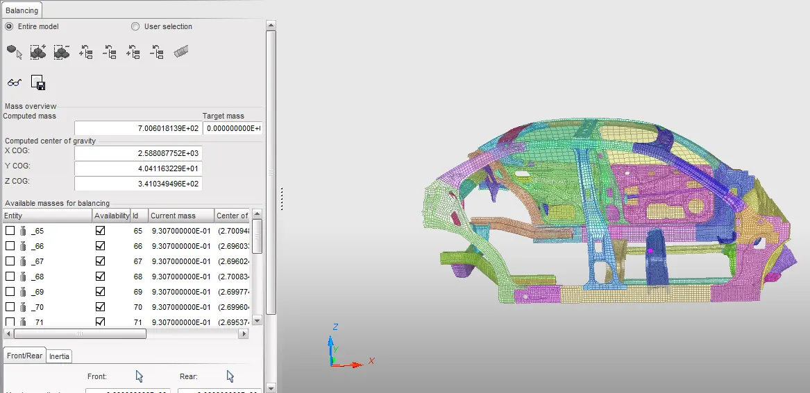
7) Then, we use the full car model to compare the COG point and then we use add mass to add masses the reqiured points on the reduced car model for correct location of the COG. We use Hypercrash for better visualization of the COG and get the required value of 700 kg as shown in the image given below.
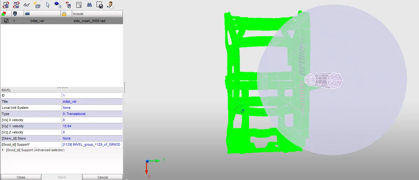
8) We then create an initial velocity along the global Y axis with a value of 35 mph = 15.6464 mm/ms as shown in the image given below.
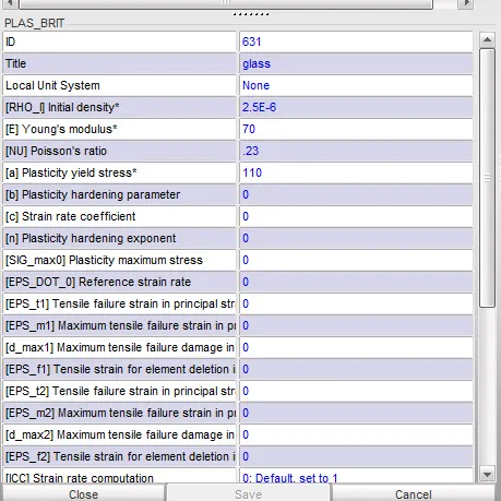
9) After that, we create failure card for the window glass so that it can shatter while the simulation is performed. For we first go to the material card and change the failure from Plas/johns to plas/brit and we input the values of the Density (ρρ), Young's Modulus (E), poisson's ratio (νν) and yeild stress (Sigy) as shown in the given below.
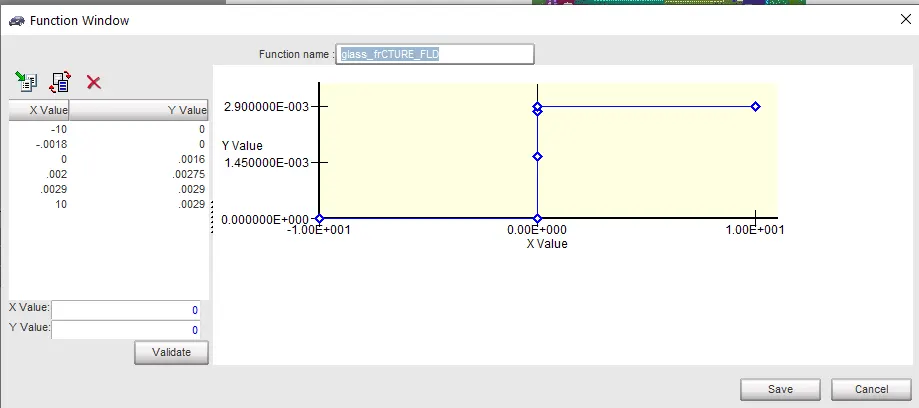
10) After we create a Failure Card for that we first the function curve with the following data points as shown in the image given below.
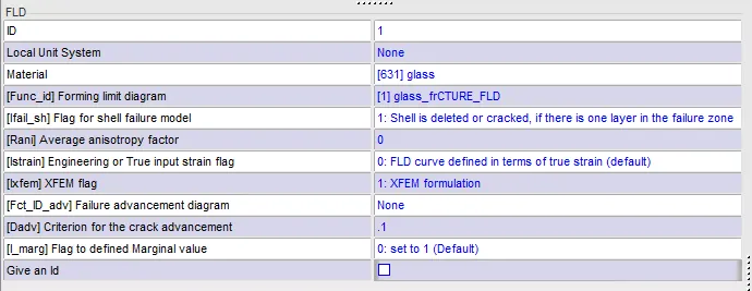
11) We input the values of the Ifail_sh =1 i.e. shell is deleted or cracked, if there is one layer in the failure zone and Ixfem=1 for cracking of the glass, then we also input the defined function curve in the Func_id as shown in the image given below.
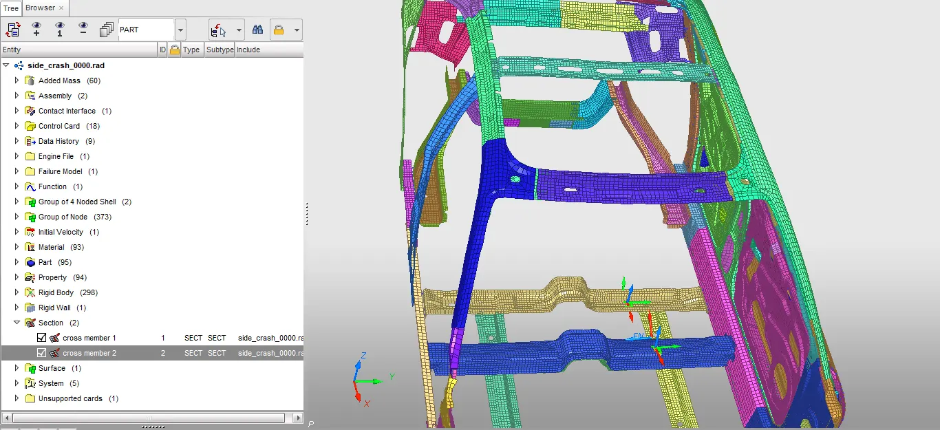
12) We create Cross section in the crossmembers present in the model to get the output as shown in the image given below.
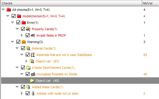
13) We perform model check using the model checker and get 1 error & 3 warnings as shown in the image given below.
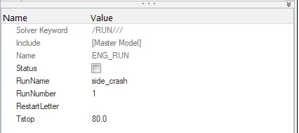
14) We clear all those errors and warnings and then, we finally check the whether the runtime = 80 ms and time step =0.5 to 0.1 microseconds. We find that, both the values are correct as shown in the image given below.
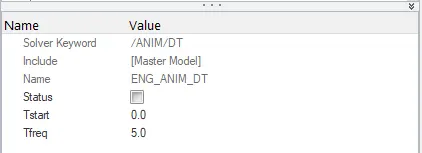
15) We proceed to run the simulation by clicking on Analysis module and clicking on radioss option as shown in the image given below.

2. Simulation Results:
1) On running the simulation, we get the values of energy error and mass error in 1.out file as shown in the image given below.
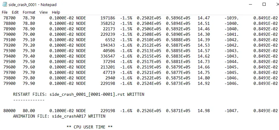
Energy Error: -1.6 %
Mass Error: 0.008493
No of cycles: 80,001
2) We go to Hyperview and import the file '.h3d' then, we check for contour plot on Von mises stress with simple average method and Displacement in the form of animations as shown below.
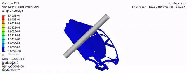
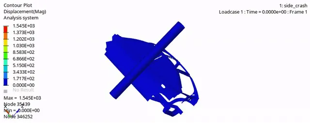
Max Von Mises Stress: 0.3423 GPa
Max Displacement: 1545 mm
We find that, the window glass shatters on impact of the BIW model with the pole because we have defined the failure card PLAS/BRIT with the function curve so that it shatters on impact.
3) We then, proceed to plot the graphs the results with the help of Hypergraph 2D.
4) We plot graphs for all the energies which include internal energy, kinetic energy, Contact energy, Hourglass energy & total energy are shown in the image given below.
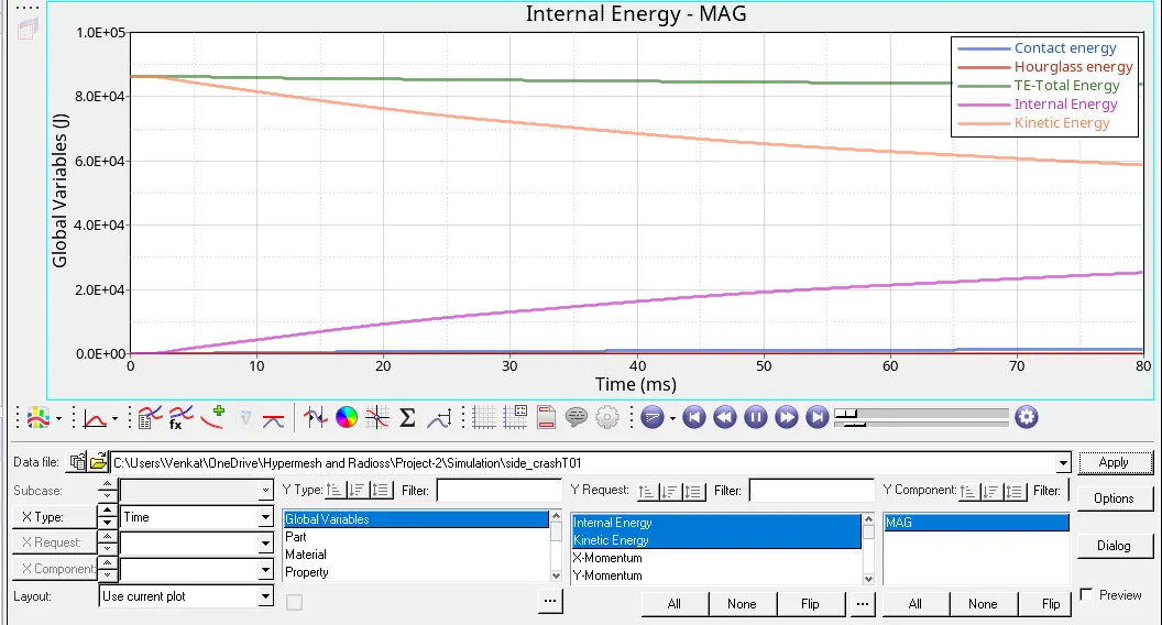
In this plot, we can see that the Internal energy increases to almost 25,000 J at the end of simulation, Kinectic Energy decreases from 88,000 J to 59,000 J at the end of the simulation, the Hourglass energy & Contact energy remain at 0 J for all the time since we use the recommended shell formulations for all the components & there is also no contact between till the completion of the simulation and finally, the Total Energy also remains constant i.e. at 88,000 J till the end of simulation since there is no significant energy loss.
5) We plot graph for rigid wall forces as shown in the image given below.
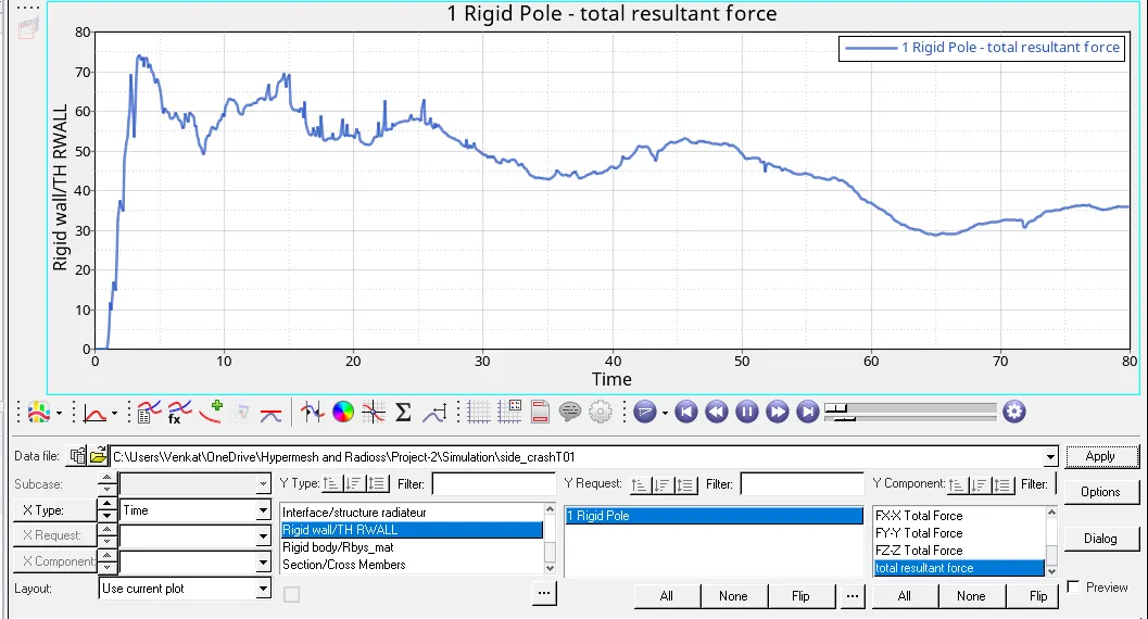
In this plot, we can see that at the event of crash the rigid wall resultant forces are more i.e. at 75KN , then it decreases since the crash event is finished .
6) We plot graphs for all the cross sectional forces at the cross members as shown in the image given below.
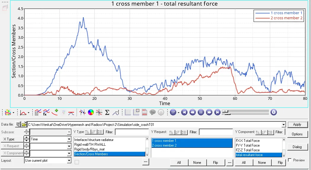
In this plot, the forces are high at the beginning of the impact a maximum of 4kN and 1.5kN was recorded during the run time for cross members 1 and 2 respectively. In the end, the forces can be seen to rise again, this might be due to self impact.
7) We plot graphs for instrusions on the B pillar,hinge pillar and fuel tank region as shown in the image given below.
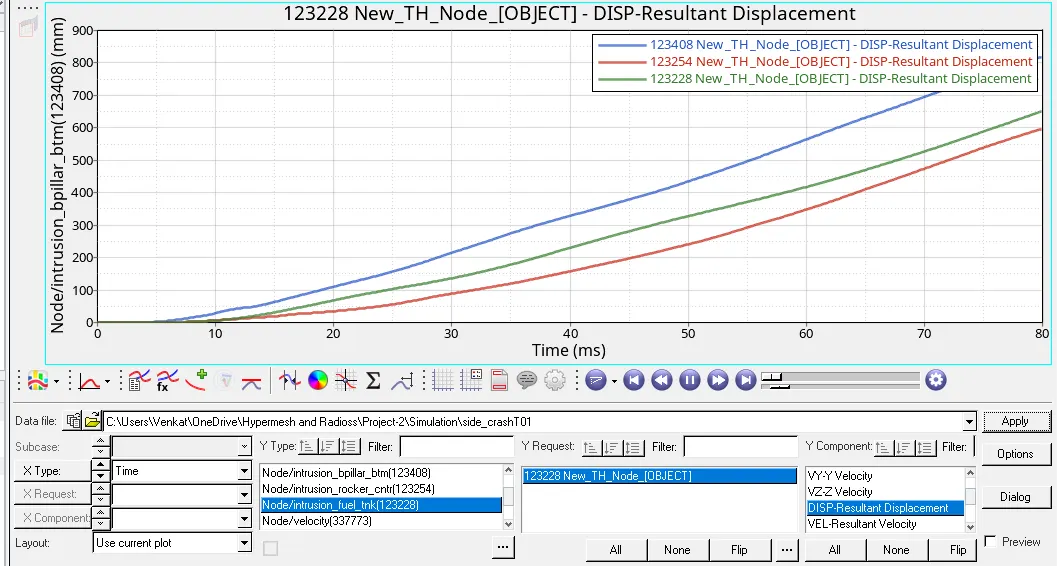
In this plot, the intrusions are measured as relative displacement of these nodes(123408, 123254, and 123228). The intrusion recorded for the hinge pillar and fuel tank were 633 mm and 636 mm respectively and an intrusion of 837 mm was noted for the node on the B-pillar region.
8) We plot graph for peak velocity of inner node of the door as shown in the image given below.
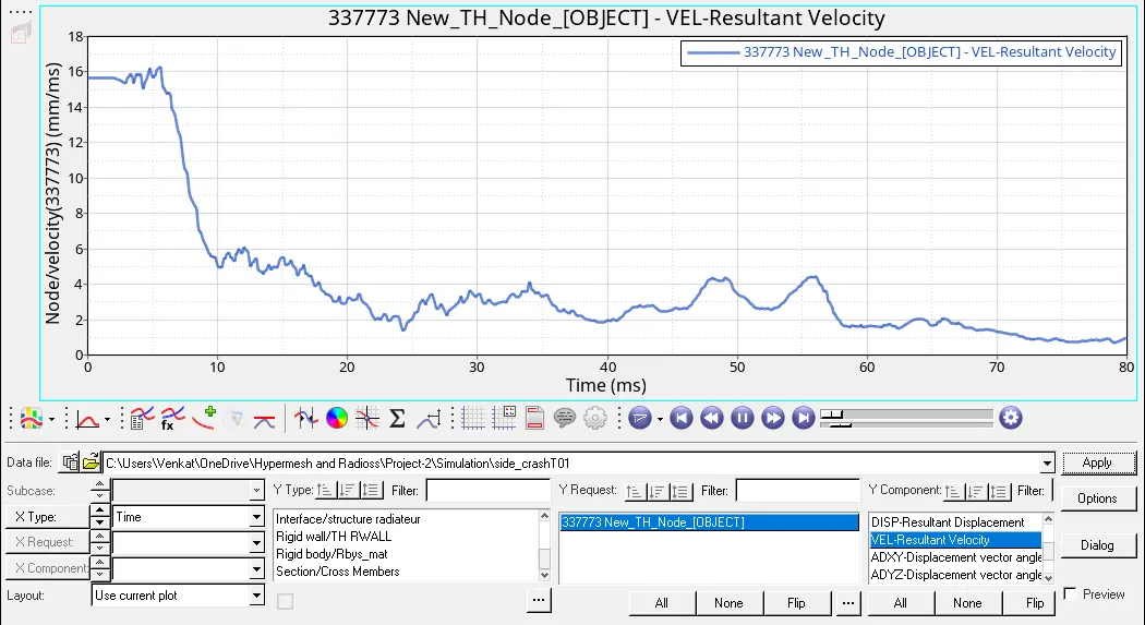
In this plot, the velocity values recorded by from in the TH for node 337773 are shown. Peak velocity of 16.58 mm/ms was observed. The velocity of the door has reduced to almost 1.5 mm/ms towards the end of the simulation.
Conclusion:
1) We have set-up the model for Side Crash according to the given parameters in the aim.
2) We have checked for penetrations and intersections in the model.
3) We have created a cylindrical pole rigid wall according to the FMVSS standards.
3) We have also used the model checker to find errors and warnings in the model and then rectify them manually one by one.
4) We have run the simulation and we have noted that the energy error and mass errors are within the controlled limit.
5) We seen the animations for displacement and von mises stresses in the Hyperview.
6) We have also plotted the graphs for energies, cross sections, intrusions, peak velocity and rigid wall forces at all the points or sections that are given in the aim using Hypergraph 2D.
Model Link:
https://drive.google.com/file/d/133gG6jkdT8p65SP05b6CWVZs1_RJpXeZ/view?usp=sharing