Simulating Fluid Sloshing effect inside a Gear-box
Simulating Fluid Sloshing effect inside a Gear-box
Aim:-
- Use the dynamic mesh capability of Ansys Fluent to solve a simple flow-driven rigid-body motion problem.
- Compile a User_Define function (UDF) to specify flow-driven rigid-body motion.
- Perform four simulations in the Gearbox - first for 20% Immersion of gear for fluid Engine oil, second with same fluid but with 30% immersion, last two with fluid n-Heptane for 20 and 30 % immersion respectively.
- Explain Dynamic mesh with example.
- describe the Fluid sloshing effect. State either its effects are good or not.
- Explain use of the UDF (User Define function)
- Lastly, Discuss the common error that occurred in the simulation. A] Dynamic mesh failed B] Negative cell Volume detected.
Objectives:-
- Study on the lubrication techniques in the gearbox.
- Setting up a workbench for the oil splash lubrication simulation in the gearbox.
- Simplify the geometry to use it in fluent student version - convert 3D geometry to 2D model.
- Provide the proper execution of mesh over the 2D faces to avoid any further simulation error in fluent.
- Set up the fluent setup for the oil plash simulation.
- Material setup using the fluent material library and user-defined inputs.
- Understand and apply UDF in fluent and assign the right angular velocity motion to the respective gear.
- Define an adaptive fluid mesh region for the lubricant in the gearbox.
- Simulate the solution and using the same setup simulate the solution for 30% immersion of gear in engine oil, 20% immersion of gear in n-heptane, and 30% immersion of gear in n-heptane.
- Create an animation of each simulation and compare the results.
- Study the Dynamic meshing with its application in real simulations.
- Find out more about the fluid sloshing effect and also fine its effects are good or not.
- Understand the use of the UFD (user-defined functions).
- Explain the common errors “Dynamic mesh Failed”,” Negative cell volume detected” and how one can avoid them.
GEARBOX LUBRICATION
Gearboxes, like other types of moving equipment, rely on lubrication to reduce friction and provide cooling for optimal operation and life. There are several methods for lubricating a gearbox, with the most common being grease lubrication, oil splash, and forced oil.
Grease Lubrication:-
Grease Lubrication is suitable for low-speed operation, but it provides less cooling than oil and is not recommended for continuous-duty or heavy-duty, or heavily loaded applications, even at low speeds. With any lubrication, using too little lubrication prevents an adequate lubrication film from forming, but too much lubrication - especially grease - adds viscous drag and results in power loss.
Oil Splash lubrication:-
Oil splash lubrication is often used for helical, spur, and bevel gearboxes. This method is also referred to as an oil bath because it uses a reservoir is filled (or partially filled) with oil. As the gears rotate, they dip into this oil bath and splash the oil onto the other gears and bearings. But if the gear teeth are fully submerged, a condition is known as “Churning” occurs.
Essentially, churning is when the gears or bearing must work harder to “push through” the lubricant. A good analogy is walking along the edge of the water at the beach. Walking through ankle-deep water is relatively easy, but if you move to knee-deep water, walking requires much more effort.
The effectiveness of oil splash lubrication is heavily dependent on the speed of the gears. A common rule of thumb is that a tangential speed of at least 3m/s is required for splash lubrication to be effective.
Forced oil lubrication
Forced oil lubrication is preferred for high-speed applications, and includes methods such as oil mist. Oil spray, and oil drop. In the oil mist method, oil is atomized so that it saturates all areas of the gears and other internal components. In contrast, the oil spray method applies oil lubricant directly to the gears and other components, but this method is not always effective, as high centrifugal forces affect the direction of the oil spray.
The oil drop method, or “drops,” oil directly onto the surface where it’s needed. A pump takes lubrication from a reservoir and delivers it to the gears and/or bearings via an internal piping system. This method can often be found in conjunction with the splash (aka oil bath) method, where some components may be difficult to reach via oil splash.
WORKBENCH SETUP
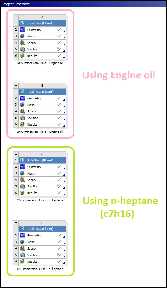
The simulation is studied by performing analysis on the following four cases.
- 20% immersion of gears using Engine oil
- 30% immersion of gears using Engine oil
- 20% immersion of gears using n-heptane (c7h16)
- 30% immersion of gears using n-heptane (c7h16)
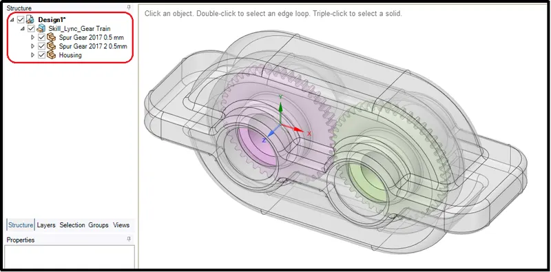
Geometry perpetration
We have a 3D solid model for the simulation but Ansys student does not support meshing more than 520000 cells and is also restricted with the use of the number of components in the model. Therefore it is a wise choice to use a 2D model instead of a 3D. so first the geometry was converted to 2d from solid for simplification.
In order to do that, first, import the geometry in fluent.
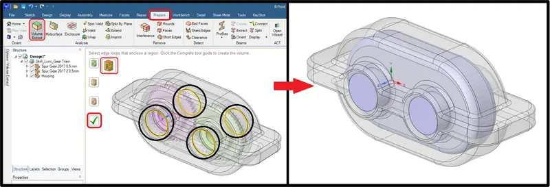
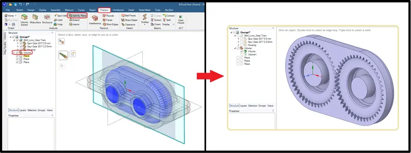
For the fluid simulation, we need to extract the fluid volume from the fluid reason. It was created using the Volume extract command present in the Prepare tab. The edge selector was enabled to select the boundary edge of the shaft holes and finally, the right check mark clicked to extract fluid volume inside the gearbox.
In order to create the 2D model, the extracted fluid volume needed to be cut through the center. Therefore, first, the planes were created using the axis of the geometry.
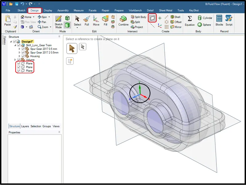
Then simply using the X-Y plane volume was split into two halves. Then one halve was hide by unchecking the component and another was used for the extraction of 2D faces.
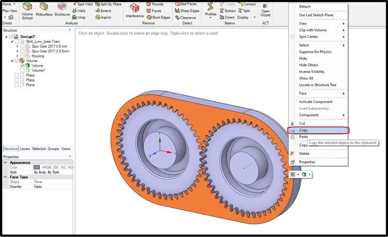
Extraction of the 2D surface is very simple in space claim. One just has to select faces. Copy it using right-click -> copy or using key ctrl+c.
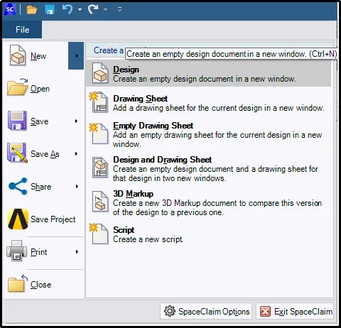
Open the new space clime design module as shown in the pictures.
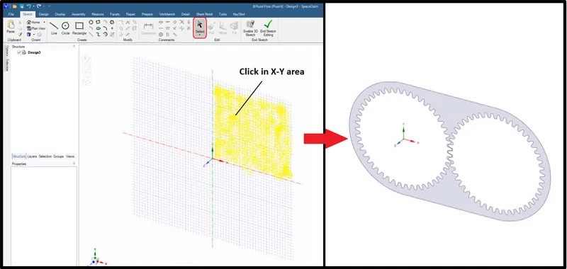
In the new design, the modeler window enables the 3skech option. Click on the right side of the X-Y plane to select the plain and paste the faces which were copied from another module. That’s how the 2D faces were extracted for this particular model.
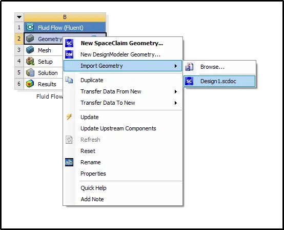
Lastly, after saving the model, one needs to import the new geometry (2D model) by right-clicking on the geometry and using the import geometry option.
MESHING
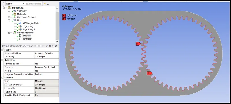
In the mesh module, firstly the name was provided as the left gear and right gear to both gears boundary as their respective order.
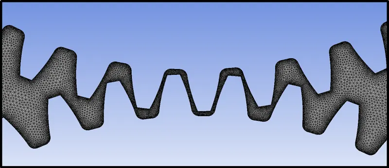
The gear boundary element size of 0.08mm was considered to capture accurate fluid motion near each tooth's surface including near the meeting area of the two gears.
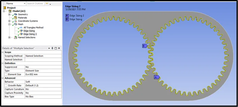
For the other regions, 0.4mm was considered with the enabled capture proximity option. It gives the advantage of defining the minimum size of elements in the geometry features that includes “gaps”.
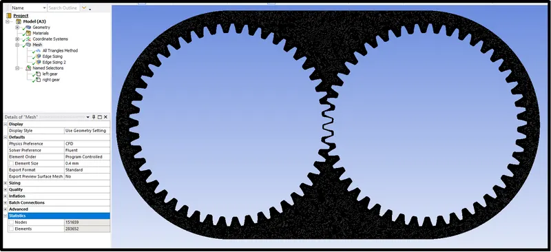
Overall 283652 numbers elements were generated after implementation of the above setting and the mesh between the meting section of two gears was enough to refine which allowed simulating proper fluid flow simulation through this region.
FLUENT SETUP
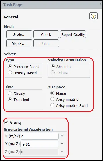
In the fluent setting type of solver was used as pressure-based. Velocity formulation was set to absolute and problem simulated for transient state simulation.
Gravity was enabled in the negative Y direction.
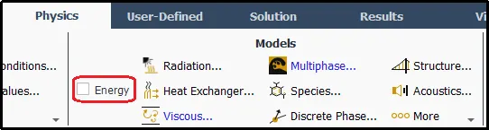
Energy Equation is turned for this study.
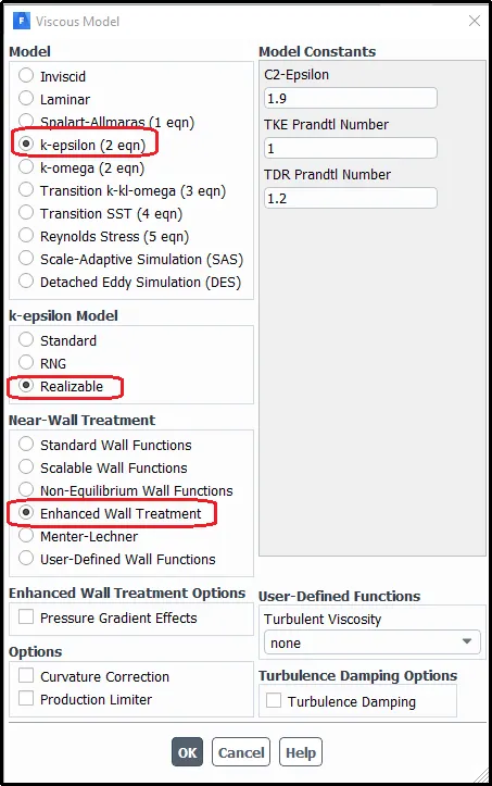
foe Viscous model- turbulent k-epsilon realizable model with the enhanced wall function option was chosen to capture the accurate flow near gear walls.
Material selection
Engine Oil:-
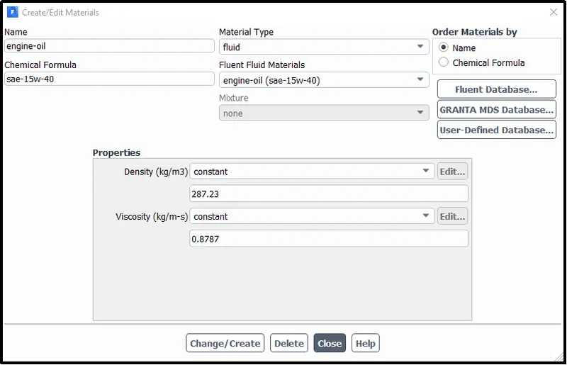
n-heptane-liquid(c7h16):-
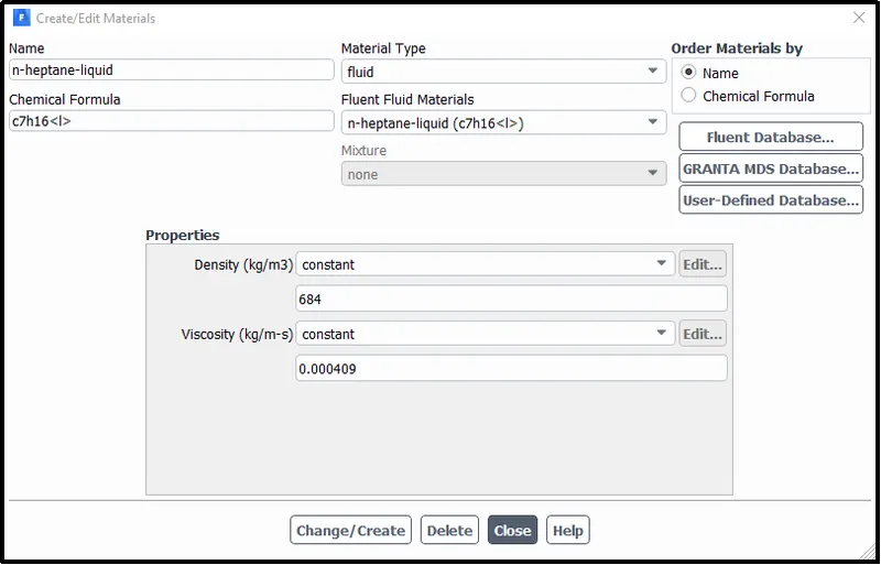
Air:-
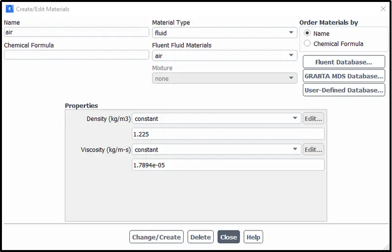
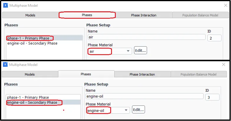
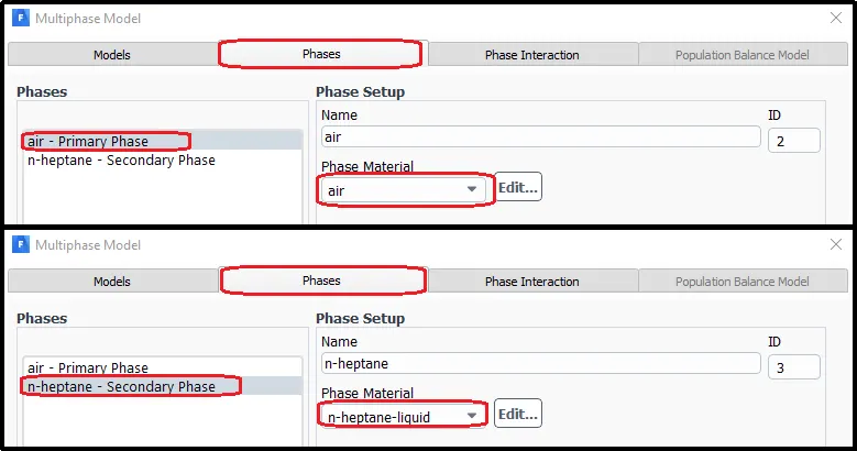
In the multiphase model, the volume of fluid option is selected with an implicit solver.
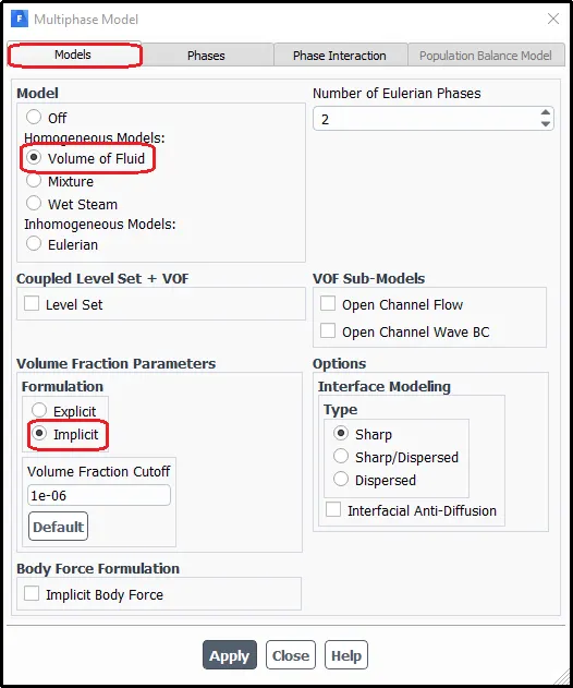
For the first two cases
For the last two cases
UDF (User Define function)
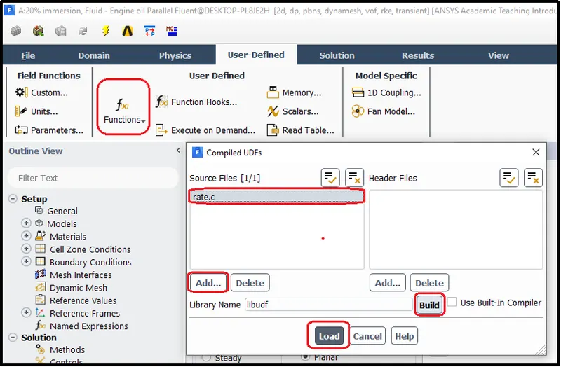
Furthermore, to define the boundary motion of the gear UDF (user Define function) was used. The file named 'rate.c' contains the UDF that was loaded in fluent. Which carry information of angular velocity and linear velocity information of the gear.
Defining a UDF:
The udf.h header file contains the following:
- Definitions for DEFINE macros
- # include compiler directives for C Library function header files
- Header files for other ANSYS FLUENT - supplied macros and functions.
A UDF should begin with #include following with “udf.h” following by whichever macros to be used can be defined,
#include "udf.h"UDFs are implemented in FLUENT code as macros. The general format for defined macros is the macro name that is defined followed by an underscore with the UDF name in parenthesis followed by a comma and then mentioning the variables that are to be passed, as shown below.
DEFINE_CG_MOTION(right_motion, dt, vel, omega, time, dtime)The definitions for DEFINE macros are contained in the udf.h header file, hence it is not possible to have something else defined in the UDF that is outside the udf.h header file.
Where,
DEFINE_CG_MOTION defines the dynamic motion with the fixed center of gravity. Its enable the rotary motion of component within there center of gravity. This function has the following six arguments.
- right_motion - the name of the UDF
- dt - pointer or structure that chose the dynamic mesh data.
- vel - linear velocity to the dynamic mesh zone
- omega - angular velocity
- time - to define time
- dtime - time step
{
	vel[0] = 0.0;
	vel[1] = 0.0;
	vel[2] = 0.0;

	omega[0] = 0.0;
	omega[1] = 0.0;
	omega[2] = 2.0e2; /* [rad/s]*/
}
For this project velocity and omega inputs from udf were considered.
vel[0] = 0.0; vel[1] = 0.0; vel[2] = 0.0; represents the velocity at X, Y, and Z directions. And, same thing is apply for the omega also, therefore, omega[0] = 0.0; omega[1] = 0.0; omega[2] = 2.0e2; /* [rad/s]*/ represents the angular velocity along X, Y, and Z direction.
Similarly, we defined the motion for the left gear.
DEFINE_CG_MOTION(left_motion, dt, vel, omega, time, dtime)
{
	vel[0] = 0.0;
	vel[1] = 0.0;
	vel[2] = 0.0;

	omega[0] = 0.0;
	omega[1] = 0.0;
	omega[2] = -2.0e2; /* [rad/s]*/
}
Using the above information the code was written.
Complete UDF script file
#include "udf.h"

DEFINE_CG_MOTION(right_motion, dt, vel, omega, time, dtime)
{
	vel[0] = 0.0;
	vel[1] = 0.0;
	vel[2] = 0.0;

	omega[0] = 0.0;
	omega[1] = 0.0;
	omega[2] = 2.0e2; /* [rad/s]*/
}
DEFINE_CG_MOTION(left_motion, dt, vel, omega, time, dtime)
{
	vel[0] = 0.0;
	vel[1] = 0.0;
	vel[2] = 0.0;

	omega[0] = 0.0;
	omega[1] = 0.0;
	omega[2] = -2.0e2; /* [rad/s]*/
}
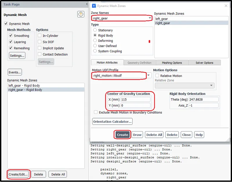
Using Dynamic mesh setting the motion from UDF was applied to the respective gear.
Left motion for Left gear with its center of gravity.
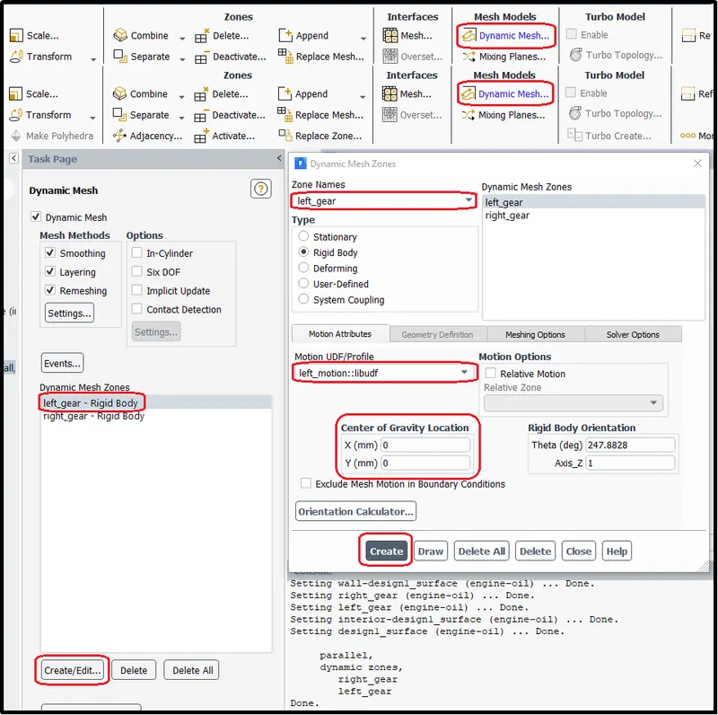
Right motion for right gear with its center of gravity.
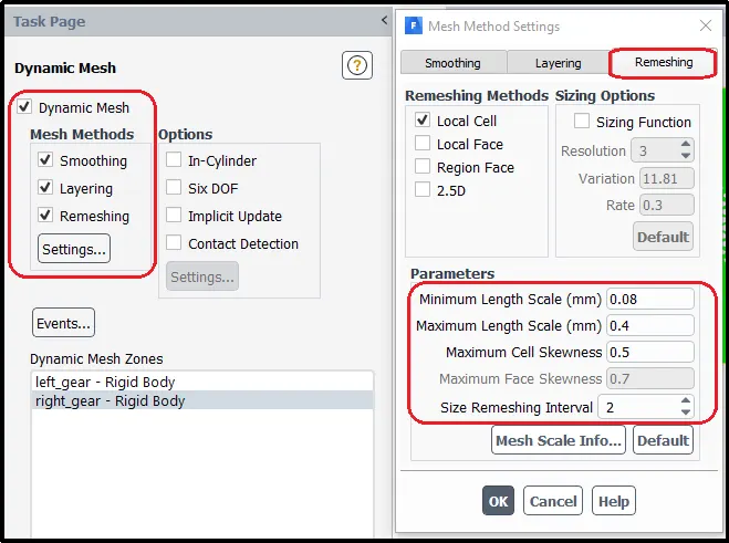
Following final remeshing parameters were considered to avoid any dynamic mesh regeneration failure.
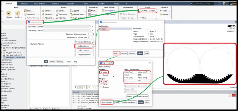
Mesh Region adaption
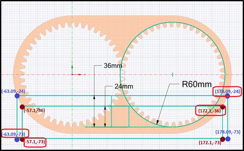
To define the fluid area adaptive meshing technique was used. Quad area selection was used to select the mesh level. To capture the properly submerged region min and max coordinates were recorded.
For 20% immersion of the gear, region coordinates are represented using dark red dots and for 30% immersion of gear, region coordinates are represented by the blue dots in the following figure.
The final fluid mesh reason was registered using those recorded coordinates as shown in the below picture.
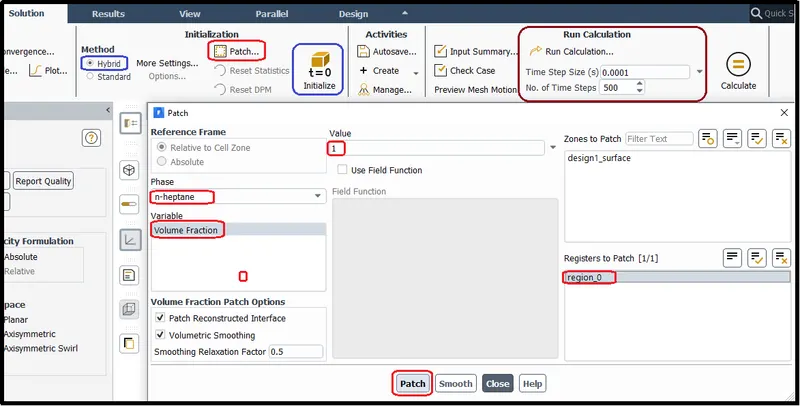
Lastly, before running the simulation initialization is needed for that the hybrid initialization was chosen and the adapted mesh region was patched with the second phase of the lubricating fluid either engine oil or n-heptane. The solution ran for the 500-time step with a time step size of 0.0001.
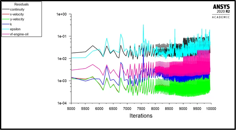
Residual Plot:-
Residual plots for all the simulations are almost similar to each other which plots the results below-mentioned way.
RESULT ANIMATIONS AND OBSERVATION FROM EACH SIMULATION:-
[1] 20% immersion, Fluid - Engine oil
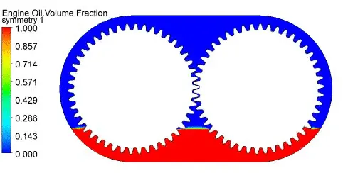
In the above animation, we can observe the engine oil splashing very effectively which fulfilling the purpose of lubrication over every part inside the gearbox.
At starting of the half rotation, we can observe, first, the engine oil is carried by the pockets of the gear teeth towards the top of the gear.
After the 45o of motion, because of centrifugal force from the rotation of gear the outermost free surface layer of the engine oil starts to move outward direction towards the casing. And remaining stays intact because of the Adhesive force of gear and Surface tension of the fluid.
The engine oil is carried by grooves of the teethes striking forcefully by engine oil carried by other gear teethes at the gear teeth meeting area. This causing forced splashing of the engine oil which leads to distortion on the surface of the fluid and breaks the engine oil into small particles. This looks similar to the oil spray effect above the gear meeting point.
This small particle is sprayed all over the inside surface of the gearbox including on the other gears and bearing or other parts present in the gearbox.
[2] 30% immersion, Fluid - Engine oil
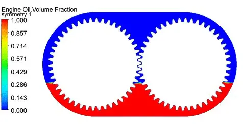
If we compare the gear sloshing effect of engine oil in the gearbox of 30% immersion of gears with the 20% immersion of gears we can notice the same phenomenon of the gear splashing as explained above for 20% immersion. Except for the churning effect on the gears which are submerged 30% will high as compare to 20% immersed gear.
The churning effect act as a resistance to the rotation of the gears or other moving components in the gearbox.
But in this case, 30% immersion looks fine as the gear sloshing is very effective all the engine oil is spreading over all the surfaces inside the gearbox and there is very little oil is remaining after 3 to 4 rotations as the gear came in full motion.
[3] 20% immersion, Fluid - n-heptane (c7h16)
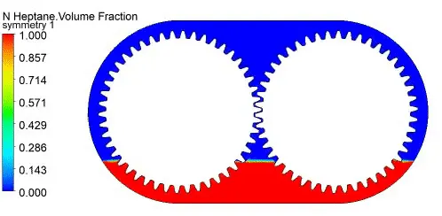
In the case of n-heptane, we can observe the fluid circulation over the gear surface almost the same as the engine oil but the fluid splashing effect is less effective with n-heptane than engine oil for the same 500-time frames. This results in less effective lubrication on other components.
[4] 30% immersion, Fluid - n-heptane (c7h16)
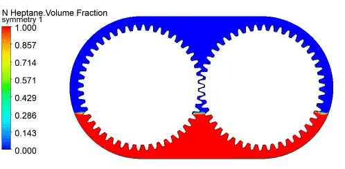
As we notice in the earlier simulation, we observed that the fluid sloshing is not that effective with the n-heptane. Additionally, if we increase the depth of lubricant we can see the churning effect is also high in the case of n-heptane which acts as a resistance to the gear motion. We can observe it in the second rotation, gear teethes cutting the surface of fluid which forming the vortex/eddies in groves of the gear teethes.
At the same time period, the fluid circulation is less while using n-heptane than the engine oil.
n-heptane, which has a high viscosity, does not flow sufficiently as the gear teeth engage to protect mating surfaces and provide cooling.
Apart from the above reasons n-heptane use is avoided in the gearbox as it is highly flammable, its vapor-air mixtures are explosive. Therefore it is hazardous for health.
DYNAMIC MESHING
Dynamic meshing refers to a simulation in which the computational grid changes dynamically during the run of the CFD simulation. This opens up the possibility to simulate flows where the geometry changes with time.
In ANSYS FLUENT the dynamic mesh capability is used to simulate problems with boundary motion, such as check valves and store separations. The building blocks for dynamic mesh capabilities within ANSYS FLUENT are three dynamic mesh schemes, namely, smoothing, layering, and remeshing. A combination of these three schemes is used to tackle the most challenging dynamic mesh problems.
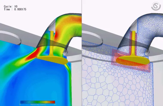
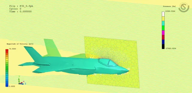
Some examples of Dynamic meshing
Air intake process of an IC Engine
Parts or debris interacts with air crafts
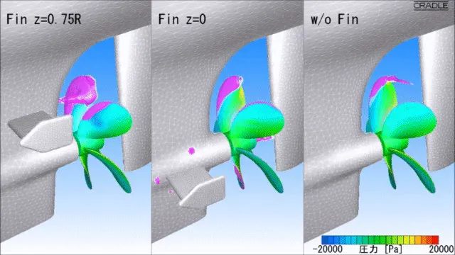
Investigation of Propeller cavitation
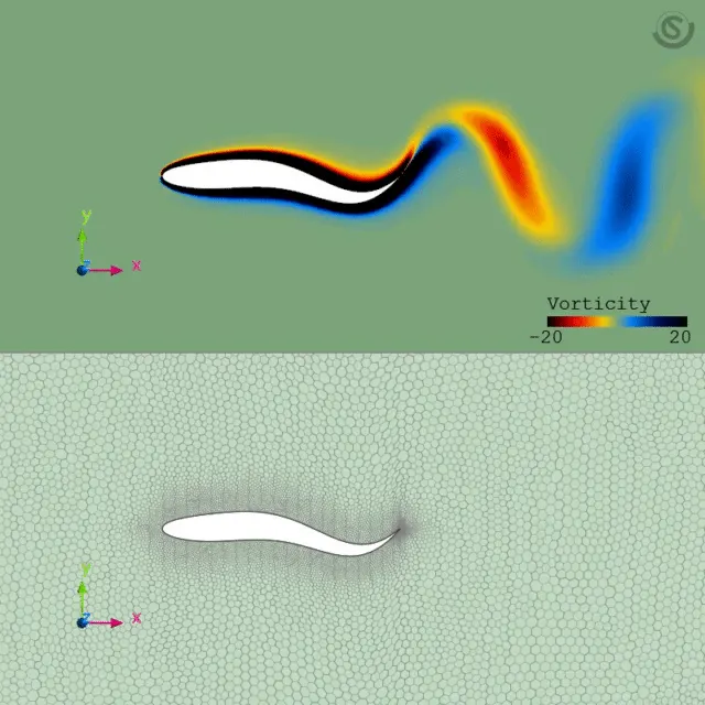
Morphing profile
FLUID SLOSHING
In Fluid dynamics, slosh refers to the movement of liquid inside another object. Sloshing is the motion of a free-surface liquid in a particular filled vessel, experienced in the marine, automotive, rail, and aerospace industries.
Effect of Fluid sloshing
- During sloshing, the liquid exerts a dynamic force on the surrounding vessel, which may cause leakage or damage to the vessel or its supporting structure.
- The sloshing motion is a highly nonlinear and random process depending on vessel motion, liquid dept, liquid properties, and vessel geometry.
- Resonance also plays a role when the external forcing frequency is closed to a natural frequency of the liquid volume.
- But unlike other cases sloshing in the gearbox plays an important role which helps to lubricate other gears and bearings present in the gearbox. And its effectiveness mostly depends on the speed of the gears and the viscosity of the liquid
USER DEFINE FUNCTION (UDF)
A UDF is basically a C program or a C function that can be dynamically loaded with Ansys Fluent to enhance its standard features. The features of a typical UDF are as follows:
- Must be defined using DEFINE macros supplied by Fluent.
- Must have an include statement for the udf.h file.
- Use predefined macros and functions to access Fluent solver data and to perform other tasks.
- Are executed as interpreted or compiled functions.
- Are hooked to Ansys Fluent solver using graphical user interface dialog boxes.
UDF can be used for several applications
- Customize boundary conditions.
- Material property definitions.
- Adjust computed values on a once-per-iteration basis
- Initialize with a previous solution.
- Execute at the end of an iteration.
- Upon exit from Ansys Fluent
- Enhance post-processing.
- Enhance existing Ansys Fluent models (such as discrete phase model, multi-phase mixture model, discrete ordinates radiation model)
COMMON ERROR DURING SIMULATION
Dynamic Mesh Failed
The dynamic mesh model in Fluent can handle both structured and unstructured meshes. However, Moving deforming mesh does not remesh structured cells - only unstructured mesh.
This error occurs in the simulation if the mesh is getting too much deformed so that the mesh quality deteriorates and remeshing goes wrong. Because of high elongation or compression mesh in dynamic meshing, it produces another error - Negative cell volume.
Negative Cell volume
When a negative or inverted volume appears during the meshing process it is impossible to run the solution process. This kind of problem is associated with the meshing algorithms during the meshing of complex geometries.
Possible factors for causing this error:
- Overlapping nodes
- Significant mesh motion (relative to cell size) per step.
Solutions to avoid the above errors
- Use of tetra mesh in the dynamic zone. (moving)
- Provide appropriate smoothing parameters.
- Verify time step size - distance moved in the single time step must be less than the mesh size in the dynamic zone.
- Adjustment of remeshing interval - it should be near 1to 3 (default value will be 5).
Conclusion:-
- In the case of the gearbox, effective sloshing is highly vital to lubricate other all moving and rotating components such as other gears and bearings of the shaft inside the gearbox.
- Engine oil level is again the important factor. A higher level of lubricant can cause churning on gears, which is resisting force by the fluid to the moving components. And the very lower level of lubricant can lead to a less lubrication effect which can cause wear and tear of gear teeth. Also high frictional heating inside the gearbox.
- Regardless of the lubrication method used, the right type of lubrication is critical to gearbox performance. And of the parameters involved in selecting a lubricant, viscosity is the most important. Choice of the lubricating fluid plays important role in the lubrication of the gearbox. Good lubricant provides better sloshing with the motion of gear and produces a less churning effect. In this project engine, oil is a better example of a good lubricant.
- The main requirements for a lubricant (an engine oil) are defined temperature-viscosity properties, protection against wear and corrosion, keeping the engine clean, holding particles like soot or abrasive in suspension, yield strength under compression, and many more.
- A lubricant with a viscosity that is too high for the application (i.e the lubricant is too “thick”) won’t flow sufficiently as the gear teeth engage to protect mating surfaces and provide cooling. But lubrication with a viscosity that’s too low won’t provide a sufficient film thickness to prevent metal-to-metal contact between the mating surface.
- UDF can be used for applications like customizing boundary conditions, material property definitions, adjusting computed values, for initialization of the previous solution, to enhance models, and post-processing.
- “Dynamic mesh error”,” Negative cell volume” - this error can be avoided by the use of tetra mesh in the dynamic zone, implementation of appropriate smoothing parameter, with use of proper time step, and using low remeshing intervals.
References:-
[1] Gearbox Lubrication - https://www.motioncontroltips.com/gearbox-lubrication-best-methods/#:~:text=Oil%20splash%20lubrication%20is%20often,the%20other%20gears%20and%20bearings.
[2] The viscosity of engine Oil - https://wiki.anton-paar.com/en/engine-oil/
[3] Dynamic Mesh - https://cfd.ninja/ansys-fluent/ansys-fluent-dynamic-mesh/
[4] Body Dynamic simulations - https://mantiumcae.com/cradle-cfd-germany/
[5] Tank Sloshing simulation:- https://www.veryst.com/case-studies/tank-sloshing-simulation#:~:text=Sloshing%20is%20the%20motion%20of,vessel%20or%20its%20supporting%20structure.
[6] Writing a User Defined Function (UDF) for CFD Modeling - https://www.learncax.com/knowledge-base/blog/by-category/cfd/writing-a-user-defined-function-udf-in-ansys-fluent#