Steady State Simulation of Cyclone separator with Discrete Phase Modelling Using Ansys Fluent
Aim:
The Major Objective of this project was to set up a steady-state model to analyse the cyclone separator using Ansys-Fluent and calculate the separation efficiency and pressure drop.
Introduction:
A cyclone separator, also known as a cyclonic dust collector, is a commonly used air pollution control device that capable of cleanses flue gases of the particulate matter before such gases exit into the atmosphere. It's a method of collecting up to 99% of airborne waste in an easy-to-empty container beneath the cyclone.
These devices are primarily labelled as pre-cleaners, as they are instrumental in removing large and abrasive particles from flue gases, which then go through additional filtration processes to remove fine particulate matter. The relevance of cyclone separators lies in the fact that they facilitate the first step of the flue gas filtration process. The objective of these devices is to minimize air pollution and environmental hazards caused by production plant exhaust.
In terms of filtration abilities, cyclone separators are known to remove the following particulate matter from flue gases:
- Toxic particles.
- Abrasive particles.
- Coolant mists.
- Metalworking chips.
- Explosive particulate.
- Fine powders.
- Other production plant exhaust.
The efficiency of cyclone separators is subject to various factors, including but not limited to the following:
- Size of the particulate matter.
- The density of the particulate matter.
- Size of the device.
- The velocity of the inlet gas.
- The smoothness of the separator wall.
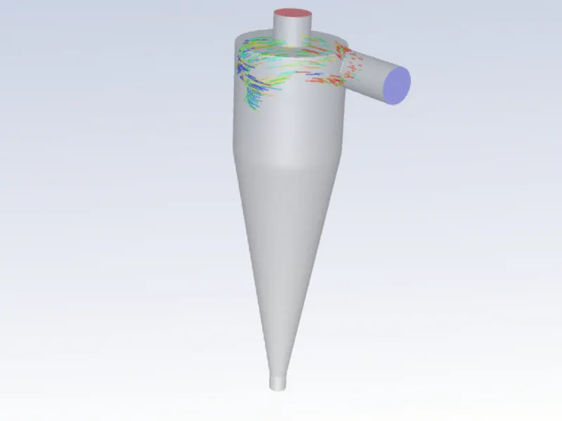
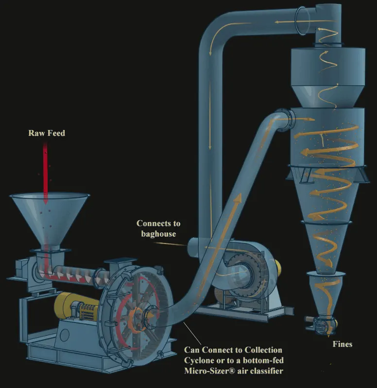
CYCLONE EFFICIENCY EMPIRICAL MODELS
1. IOZIA AND LEITH MODEL
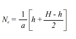
Iozia and Leith (1990) logistic model is a modified version of Barth (1956) model which is developed based on force balance. The model assumes that a particle carried by the vortex endures the influence of two forces: a centrifugal force, Z, and flow resistance, W. Core length, z_c, and core diameter, d_c, are given as
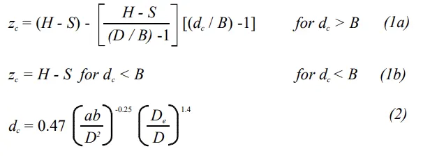
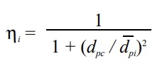
The addition made by Iozia and Leith on the original Barth (1956) models are the core length z_c and slope parameter β expression which is derived based on the statistical analysis of experimental data of cyclone with D = 0.25 m. The collection efficiency ηi of particle diameter dpi can be calculated from:
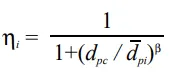
where d_pc is the 50% cut size given by Barth (1956)
2. LI AND WANG MODEL
The Li and Wang (1989) model include particle bounce or re-entrainment and turbulent diffusion at the cyclone wall. A two-dimensional analytical expression of particle distribution in the cyclone is obtained. Li and Wang's model was developed based on the following assumptions:
• The radial particle velocity and the radial concentration profile is not constant, for uncollected particles within the cyclones.
• Boundary conditions with the consideration of turbulent the diffusion coefficient and particle bounce re-entrainment on the cyclone wall are:
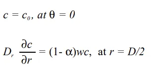
The tangential velocity is related to the radius of the cyclone by uR^n = constant.
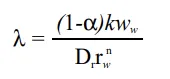
The concentration distribution in a cyclone is given as:
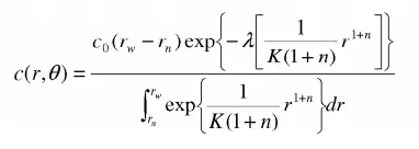
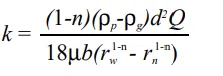
Where,
3. KOCH AND LICHT MODEL
Koch and Licht (1977) collection theory recognized the inherently turbulent nature of cyclones and the distribution of gas residence times within the cyclone. Koch and Licht describe particle motion in the entry and collection regions with the additional following assumptions:
• The tangential velocity of a particle is equal to the tangential velocity of the gas flow, i.e. there is no slip in the tangential direction between the particle and the gas.
• The tangential velocity is related to the radius of cyclone by uR^n = constant.
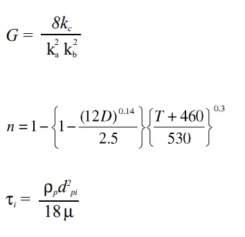
A force balance and an equation on the particles collection yields the grade efficiency η_i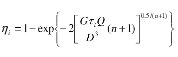
where
4. LAPPLE MODEL
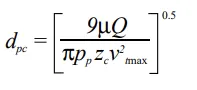
Lapple (1951) model was developed based on force balance without considering the flow resistance. Lapple assumed that a particle entering the cyclone is evenly distributed across the inlet opening. The particle that travels from the inlet half-width to the wall in the cyclone is collected with 50% efficiency. The semi-empirical relationship developed by Lapple (1951) to calculate a 50% cut diameter, d_pc, is
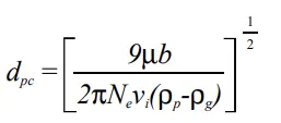
Where
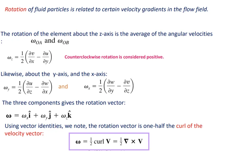
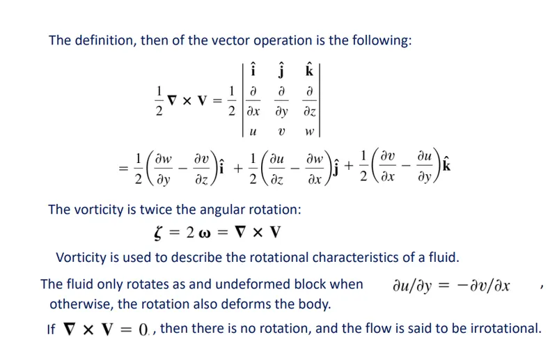
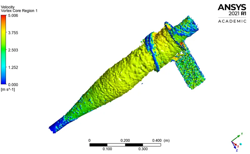
Vorticity
A Vector measure of local rotation in a fluid flow defined mathematically as the curl of the Velocity vector.

1.Geometry Creation:
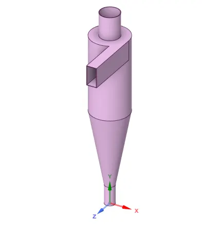
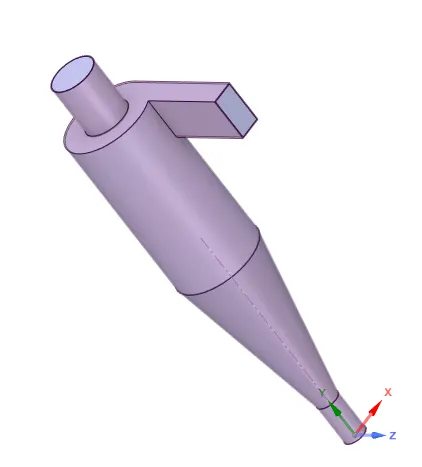
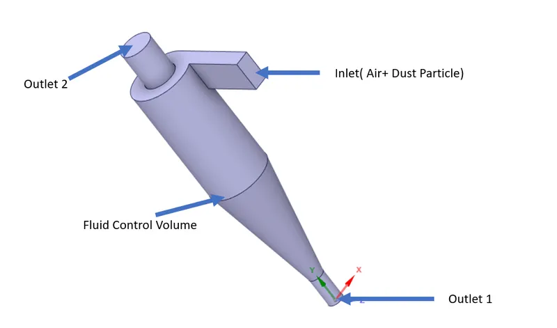
The Cyclonic Separator Geometry was designed using a separate cad package using Solidworks. Then the geometry was imported to Ansys design modular for future control volume creation as it defines the fluid flow domain important for single-phase flow with DPM. First, the fluid flow domain was created using Prepare feature.
2. Boundary Creation and Meshing
After the control volumes are perfectly created the boundary tags were created in order to assign the different boundary conditions ie. velocity, temperature(if needed), or some other physics. For this geometry, 3 different boundary tags or names were created that were used earlier to assign the boundary condition. The 3 names are Inlet, Outlet1 and Outlet 2.
Mesh was generated using TetraHedral shape elements, in order to make it more refine the body sizing method for chosen for each named selection.
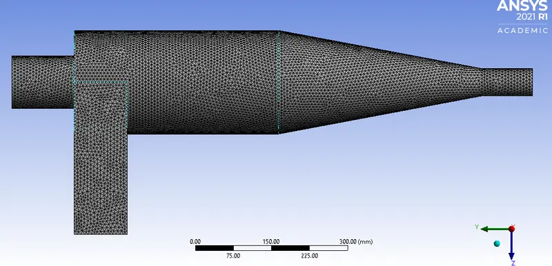
Base Mesh Size:10mm
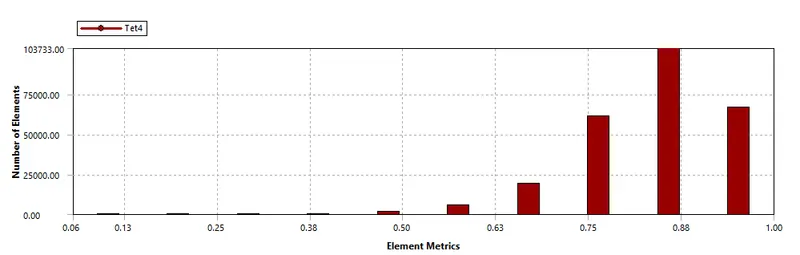
| Number of Nodes | 80164 |
| Number of Elements | 344439 |
3. Case Study Setup
For setting up the case study Ansys Fluent was used in order to simulate the case study.
The various parameter was considered while setup this case study. The case study setup dock was used to set up the problem which appears on the left-hand side of the Fluent studio
Solver type: Pressure Based Transient State simulation
Gravity with -9.81m/s^2 in y-axis was enabled
| S.No. | |||
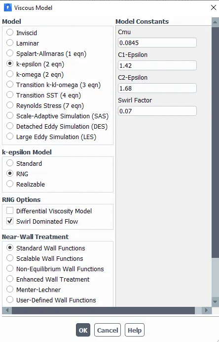
| 1 | Models |
Viscous Model-`K-epsilon -"RNG"` with Swirl Dominant Flow and standard wall function |
Viscous was Coupled with a DPM model |
| 2 | Material |
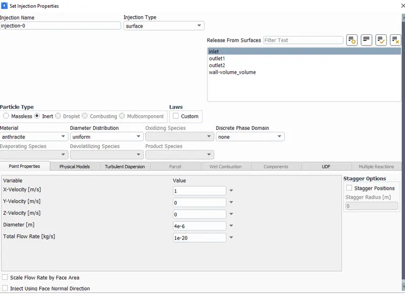
Primary phase:`Air (N2:O2::23%:77%)` Discrete Phase:Anthracite |
|
| 3 | DPM Model | An Injection was created using Anrthracite as injection particle from Inlet with a particular velocity and particular diameter of the particle. | |
| 4 | Boundary Conditions | Inlet-Velocity Inlet Z-axis-Reflect | For assigning the fluid flow |
| Outlet 1(Top)- Pressure Outlet-Escape | Zero gauge Pressure Outlet | ||
| Outlet 2(Bottom)- Pressure Outlet-Trap | Zero gauge Pressure Outlet | ||
4. Solution
For the Solution Residuals Monitor, the Magnitude was changed to 1e-6 to get more accuracy.
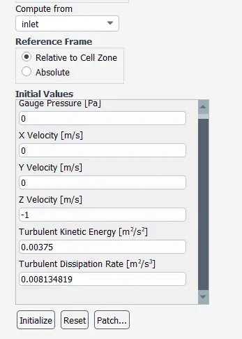
Standard Intilizization Inlet was used in order to initialize this simulation.
Solution Scheme
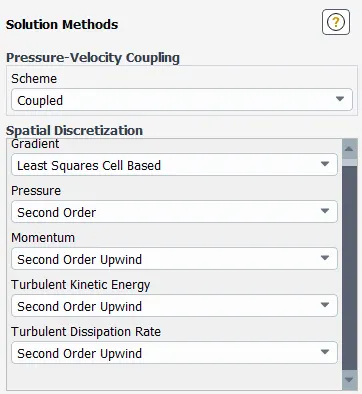
To achieve more fast and accurate converge this parameter or schemes were selected
As this was a Steady State Simulation so the Fixed Simulation was run for 500 Iterations and the results were generated easily.
####################################################################################
Efficiency V/s Different size of Dust
All the simulation has particle velocity and fluid velocity as 3m/s
Case 1:
Particle Size 4e-6m
Residual Plot
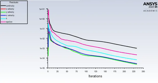
Governing Equations were solved for this problem and the residual plot was obtained while solving the case setup. The Steady-State simulation result converge was obtained around 228 iterations.
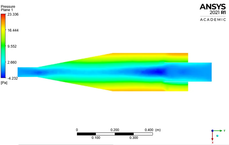
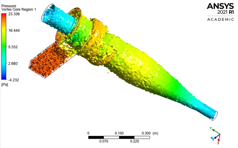
Pressure Data
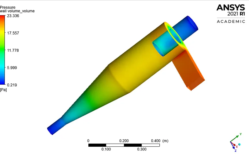
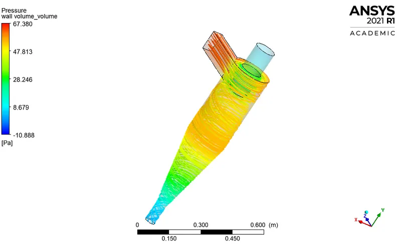
Pressure on the outer wall of the Cyclone separator
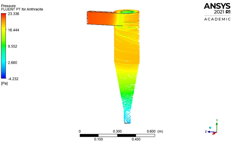
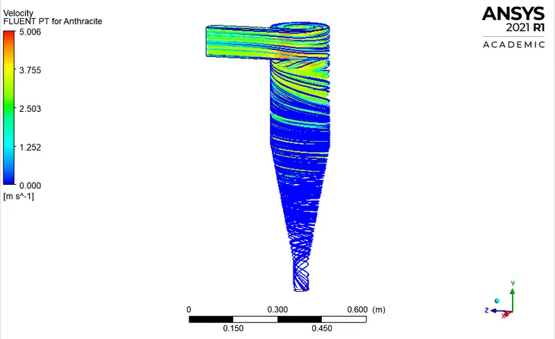
Anthracite Particle flow Streamlines
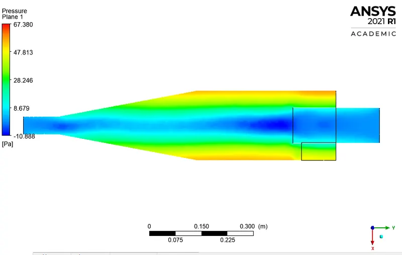
Pressure Contour
Velocity
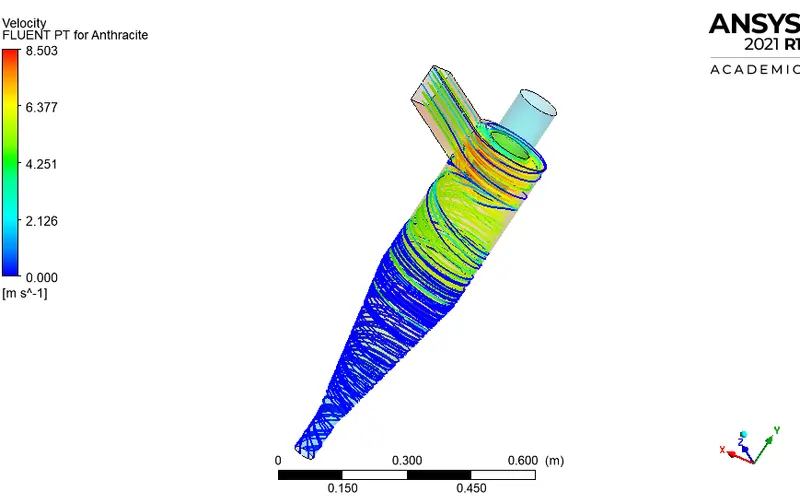
Anthracite Particle flow Streamlines
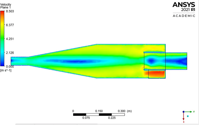
Velocity Contour
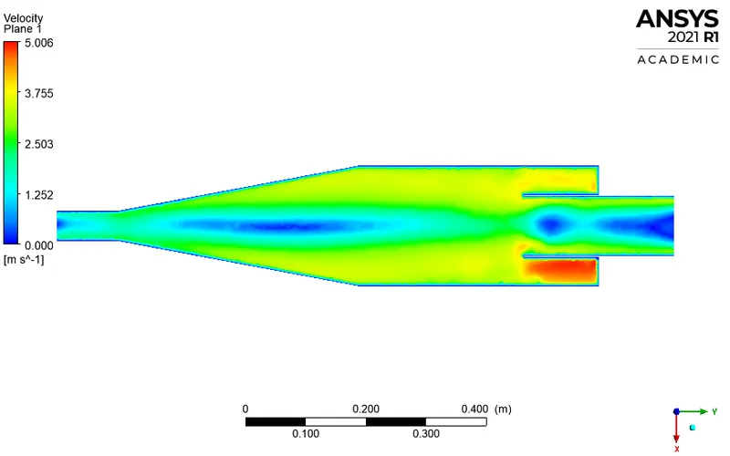
Velocity Vortex
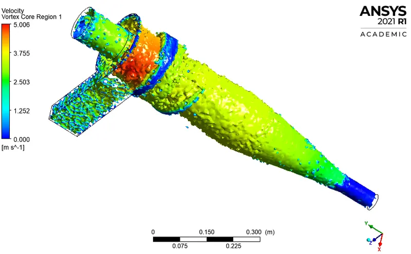
Cyclone Separator Efficiency
From DPM Data
Tracked Particle Data: 210 Trapped Particle Data:158 Escaped Particle data: 8 Incomplete 44
`"Efficiency" = "Trapped Particle"/"Total Number of Particle"=158/210*100=75.2%`
Case :2
Particle Size 3e-6m
Residual Plot
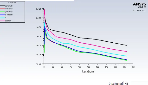
Governing Equations were solved for this problem and the residual plot was obtained while solving the case setup. The Steady-State simulation result converge was obtained around 228 iterations.
Pressure Data
Pressure on the outer wall of the Cyclone separator
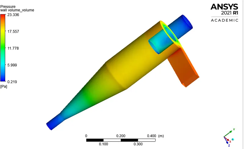
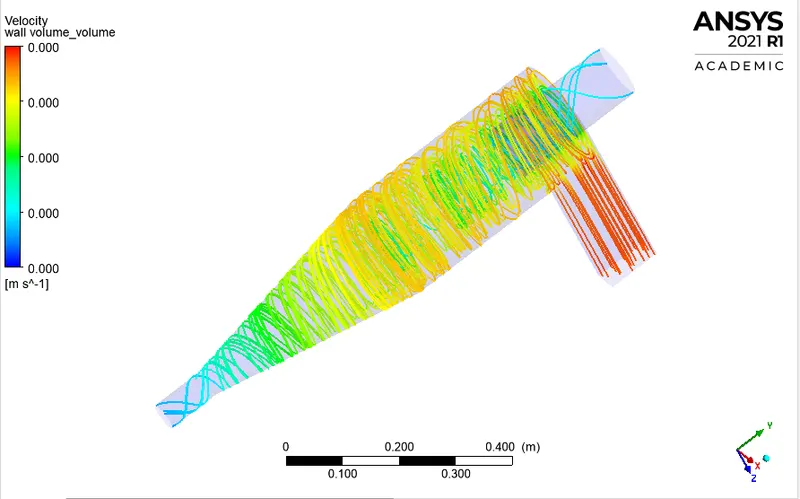
Anthracite Particle flow Streamlines
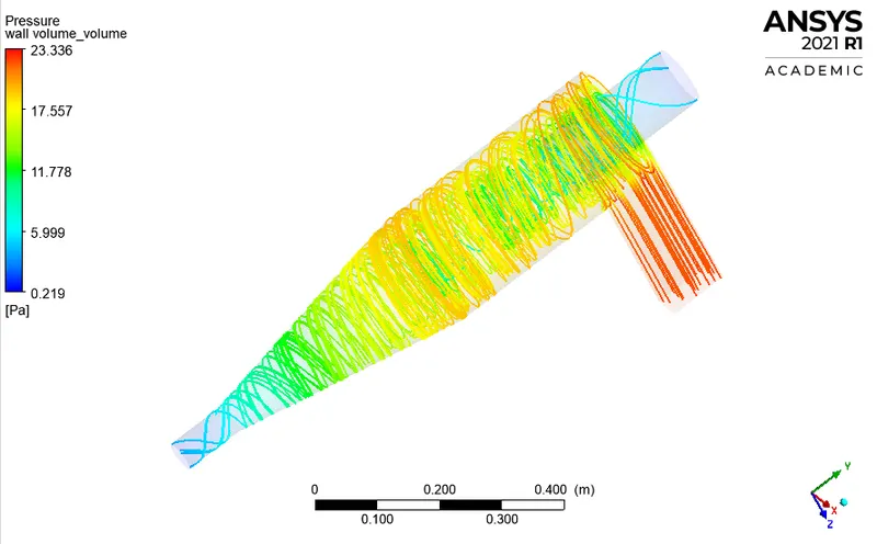
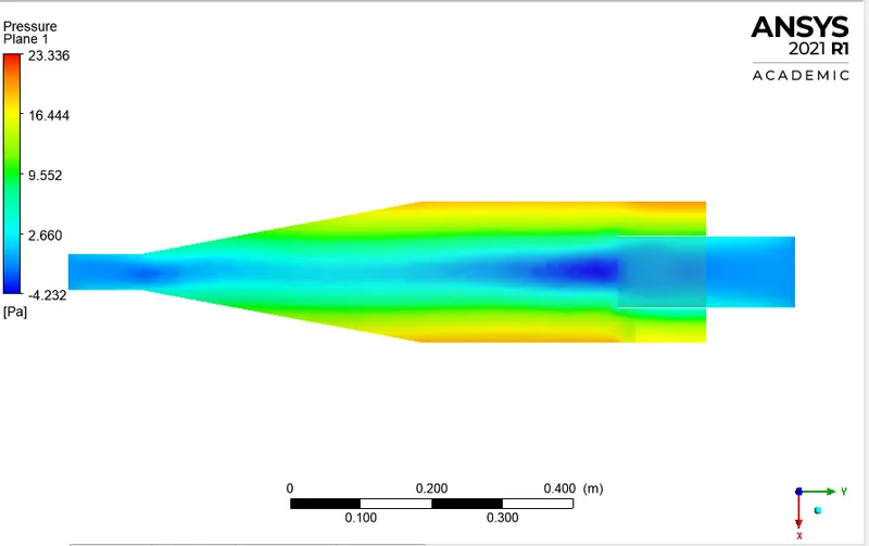
Pressure Contour
Velocity
Anthracite Particle flow Streamlines
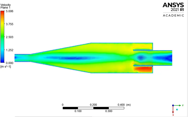
Velocity Contour
Velocity Vortex
Cyclone Separator Efficiency
From DPM Data
Tracked Particle Data: 210 Trapped Particle Data:142 Escaped Particle data: 21 Incomplete 47
`"Efficiency" = "Trapped Particle"/"Total Number of Particle"=142/210*100=67.6%`
Case:3
Particle Size 2e-6m
Residual Plot
Governing Equations were solved for this problem and the residual plot was obtained while solving the case setup. The Steady-State simulation result converge was obtained around 228 iterations.
Pressure Data
Pressure on the outer wall of the Cyclone separator
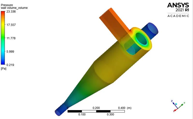
Anthracite Particle flow Streamlines
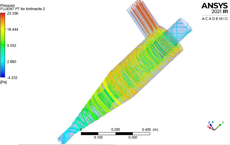
Pressure Contour
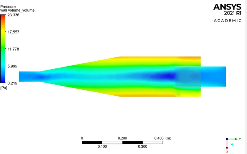
Velocity
Anthracite Particle flow Streamlines
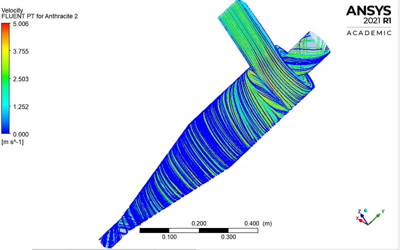
Velocity Contour
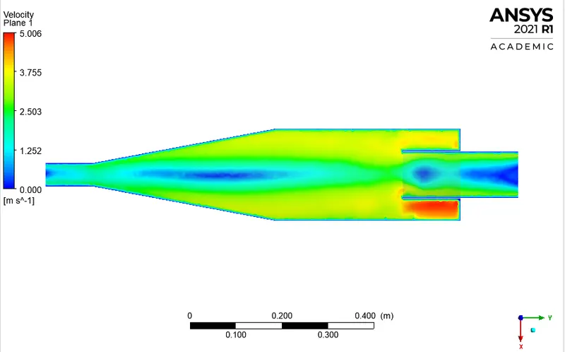
Velocity Vortex
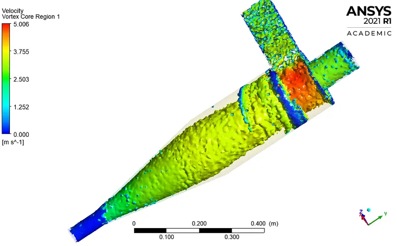
Cyclone Separator Efficiency
From DPM Data
Tracked Particle Data: 210 Trapped Particle Data:122 Escaped Particle data: 44 Incomplete 44
`"Efficiency" = "Trapped Particle"/"Total Number of Particle"=122/210*100=58.09%`
Case:4
Particle Size 1e-6m
Residual Plot
Governing Equations were solved for this problem and the residual plot was obtained while solving the case setup. The Steady-State simulation result converge was obtained around 228 iterations.
Pressure Data
Pressure on the outer wall of the Cyclone separator
Anthracite Particle flow Streamlines
Pressure Contour
Velocity
Anthracite Particle flow Streamlines
Velocity Contour
Velocity Vortex
Cyclone Separator Efficiency
From DPM Data
Tracked Particle Data: 210 Trapped Particle Data:27 Escaped Particle data: 56 Incomplete 127
`"Efficiency" = "Trapped Particle"/"Total Number of Particle"=27/210*100=12.89%`
Overall Mass Flow
| Mass Flow(kg/s) | |
| Inlet | 0.018375 |
|
Outlet 1 |
0.015047 |
| Outlet 2 | 0.00331816 |
#############################################################################
Effect of changing the flow and particle velocity for a particular dust size i.e. 4 micrometre
Case :1 Fluid Velocity: 5m/s Particle Velocity 5m/s
Residual Plot
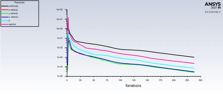
Governing Equations were solved for this problem and the residual plot was obtained while solving the case setup. The Steady-State simulation result converge was obtained around 228 iterations.
Pressure Data
Pressure on the outer wall of the Cyclone separator
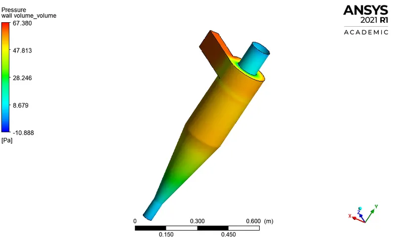
Anthracite Particle flow Streamlines
Pressure Contour
Velocity
Anthracite Particle flow Streamlines
Velocity Contour
Velocity Vortex
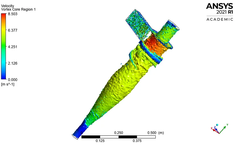
Cyclone Separator Efficiency
From DPM Data
Tracked Particle Data: 210 Trapped Particle Data:210 Escaped Particle data: 0 Incomplete 0
`"Efficiency" = "Trapped Particle"/"Total Number of Particle"=210/210*100=100%`
Overall Mass Flow
| Mass Flow(kg/s) | |
| Inlet | 0.030625 |
|
Outlet 1 |
0.0251347 |
| Outlet 2 | 0.0054434 |
Case :2 Fluid Velocity: 3m/s Particle Velocity 3m/s
Residual Plot
Governing Equations were solved for this problem and the residual plot was obtained while solving the case setup. The Steady-State simulation result converge was obtained around 228 iterations.
Pressure Data
Pressure on the outer wall of the Cyclone separator
Anthracite Particle flow Streamlines
Pressure Contour
Velocity
Anthracite Particle flow Streamlines
Velocity Contour
Velocity Vortex
Cyclone Separator Efficiency
From DPM Data
Tracked Particle Data: 210 Trapped Particle Data:158 Escaped Particle data: 8 Incomplete 44
`"Efficiency" = "Trapped Particle"/"Total Number of Particle"=158/210*100=75.2%`
Case :3 Fluid Velocity: 1m/s Particle Velocity 1m/s
Residual Plot
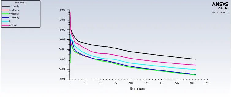
Governing Equations were solved for this problem and the residual plot was obtained while solving the case setup. The Steady-State simulation result converge was obtained around 228 iterations.
Pressure Data
Anthracite Particle flow Streamlines
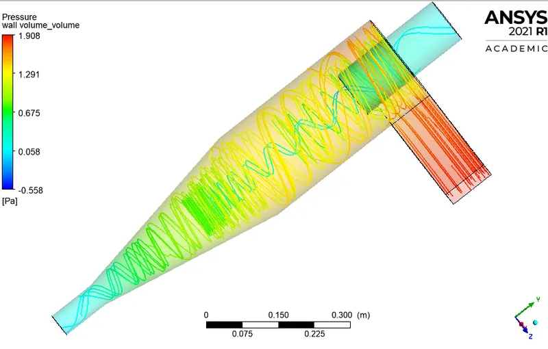
Pressure Vortex
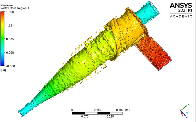
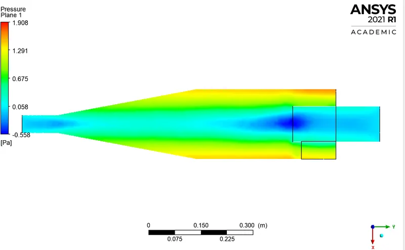
Pressure Contour
Velocity
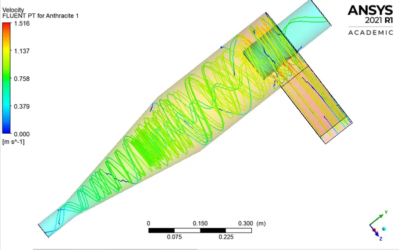
Anthracite Particle flow Streamlines
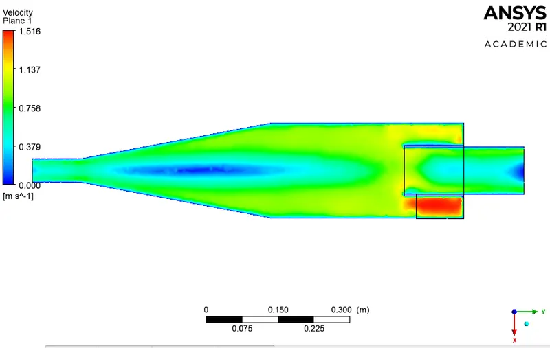
Velocity Contour
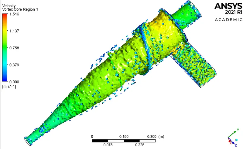
Velocity Vortex
Cyclone Separator Efficiency
From DPM Data
Tracked Particle Data: 210 Trapped Particle Data:14 Escaped Particle data:17 Incomplete 179
`"Efficiency" = "Trapped Particle"/"Total Number of Particle"=14/210*100=6.6%`
Overall Mass Flow
| Mass Flow(kg/s) | |
| Inlet | 0.006125 |
|
Outlet 1 |
0.00494 |
| Outlet 2 | 0.00117969 |
Conclusion
On changing the particle size there was no significant change in the convergence of residuals, the convergence was obtained between 225-230 iteration of the steady-state simulation.
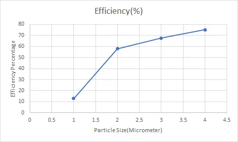
As the particle size decreases cyclonic efficiency also decreases.
There is no change in outlet pressure, mass flow rate and velocity when the particle size was varied.
The pressure drop was found to be 23.386 Pa.
| Mass Flow(kg/s) | |
| Inlet | 0.018375 |
|
Outlet 1 |
0.015047 |
| Outlet 2 | 0.00331816 |
Due to the non-linear shape of the cyclonic separator, the velocity was reduced on outlets due to the swirling motion of air.
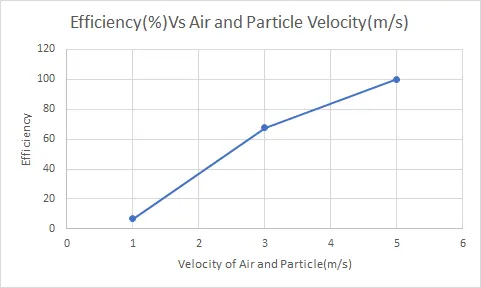
As the velocity increases the efficiency of this device also increases.
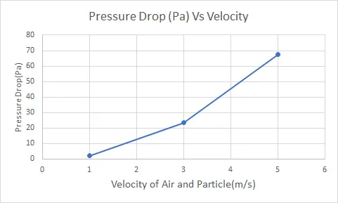
From the above pressure plots, it can be seen that pressure is higher near the wall region of this device which is due to the outer vortex. Due to higher pressure near the wall a low-pressure region is created at the centre because of which lighter particle escape from the top outlet and heavier particle settle at bottom of this device.
The efficiency of the cyclone is highly dependent on parameters such as gas viscosity, body diameter, gas exit diameter, inlet area, leakage of air etc.
The main reason for pressure might be due to following:
- Loss due to expansion of gas in the cyclone chamber.
- Loss due to rotational energy.
- Loss due to wall frictional force.