SIDE DOOR DEVELOPMENT
Report :
CATIA is the world’s engineering and design leading software for product 3D CAD design excellence.It is used to design, simulate, analyze, and manufacture products in a variety of industries including aerospace, automotive, consumer goods, and industrial machinery, just to name a few. It addresses all manufacturing organizations, from OEMs through their supply chains, to small independent producers.
If you stop and take a look around, CATIA is everywhere. CATIA is in the plane that just flew over, the car that just went silently by, the phone you just answered, and the bottle of water that you just finished.
Here, we have used the PART , SHAPE(GENERATIVE SHAPE DESIGN ) AND PRODUCT/ ASSEMBLY WORKBENCH.
1)CLASS A SURFACE :
- Class-A (or 'Strak') is a term used in specifically in automotive design. It describes the final production surface data for the aesthetic parts of the car.
- The term 'Class A' is often misunderstood, but it's generally seen as the 'Holy Grail' of surface modelling. This is because as it achieves the highest surface quality levels, and it demands a high level of automotive design knowledge as well as surface modelling skills.
- Class A represents the 'craftwork' end of the design process. Creating the main surface shapes to describe the vehicle is the primary design activity. But the painstaking, detailed craftsmanship of perfecting those surfaces, designing flanges and panel gaps is what guarantees that a beautiful design turns into a beautiful manufactured product.
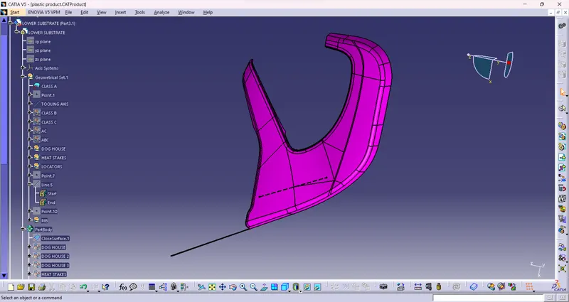
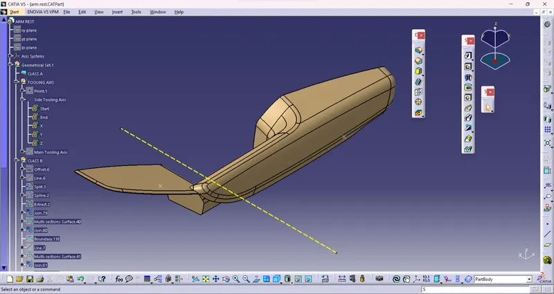
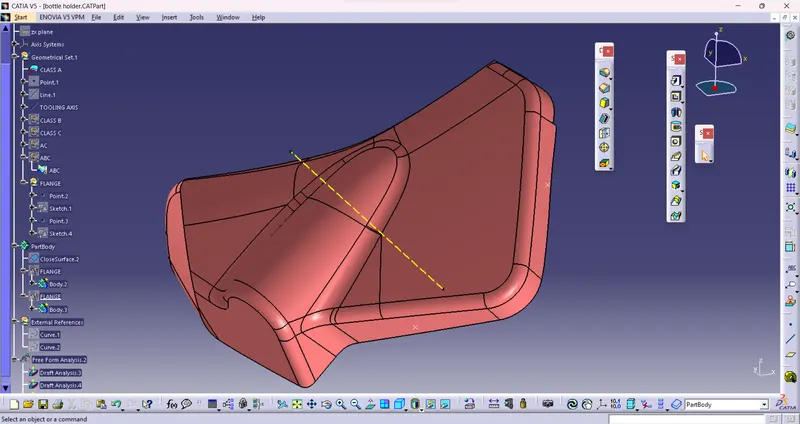
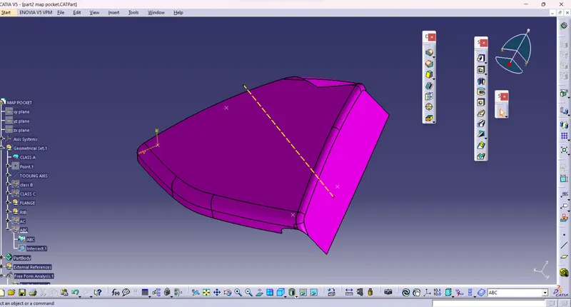
- Here we have four class A surfaces as inputs:
a)LOWER SUBSTRATE.
b)DOOR ARM REST.
c)BOTTLE HOLDER .
d)MAP POCKET.
2)TOOLING AXIS CREATION :
- Tooling axis plays important role in plastic product manufacturing and designing, this axis decides the direction in which mould is going to work while production of the component.
- The main focus while deciding the tooling axis is clearing the component in the moulding in the same axis with the minimum use of the side core for producing the component, the side core usually adds up to the cost of the component.
- For the particular component X,Y and Z can be the possible direction for the tooling axis.
- You must specify the axis system by creating the point on the surface.
- With the help of the intersect in the YZ plane create the tooling axis in YZ plane .
- With the help of the intersect in the ZX plane create the tooling axis in ZX plane.
- The last step is to bisect the two tooling axis to obtain the main tooling axis of the class A surface.
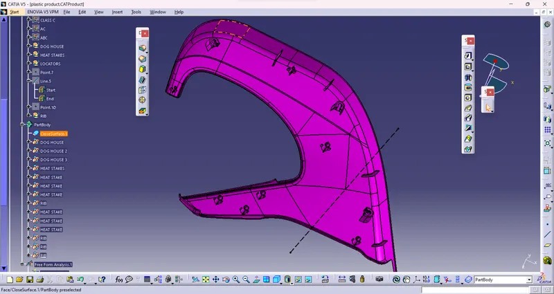
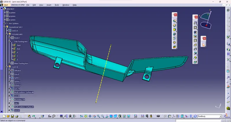
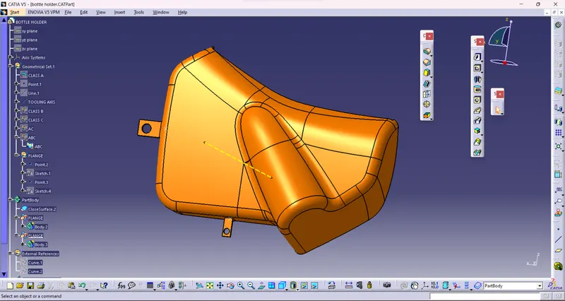
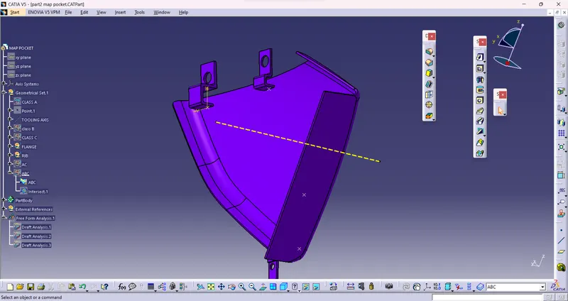
4)CREATING THE CLASS B SURFACE:
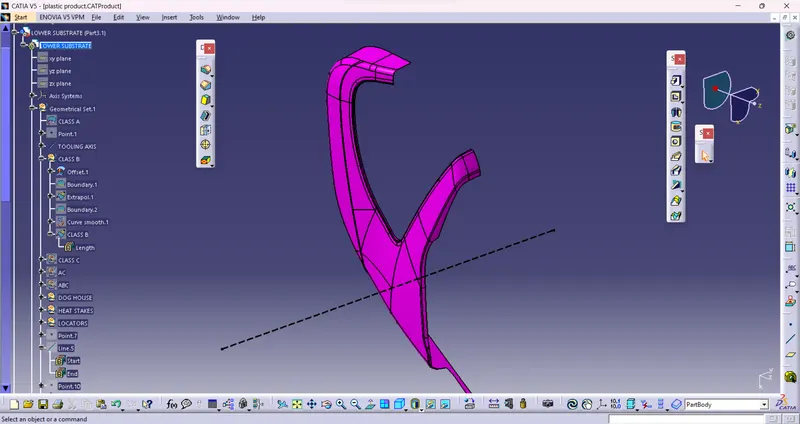
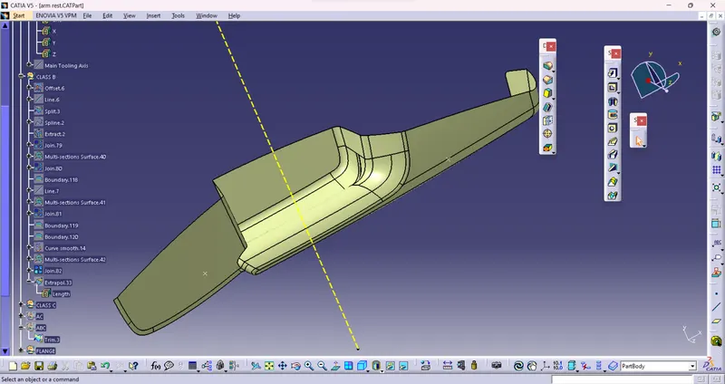
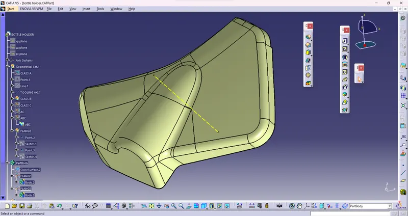
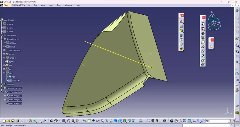
- Class B surface is the surface which is created with the help of class A surface as the reference.
- The the class B surface is the surface where all the necessary attachments and supports of the component is made .
- The main parts without the edge fillets are extracted and untrimmed and then they are extrapolated for better view.
- The extrapolated parts are then made offset with reference to the class A with the thickness of the component, here thickness of the component for base bracket is 2.5 mm.
- The offset surfaces are then trimmed to attain the class B surface.
- You can even directly offset the class A for obtaining the class B surface.
- The final class B surface must have the edge fillets similar to the class A and fillets must be given properly with a thought of maintaining same thickness throughout avoiding the flow line defects.
a)LOWER SUBSTRATE.
b)DOOR ARM REST.
c)BOTTLE HOLDER.
d)MAP POCKET
5)CREATION OF CLASS C SURFACE :
- The class C surface is the surface which is created to provide thickness to the class A surface with the help of class B surface.
- The class C surface is the middle portion of the class A and class B surfaces.
- The class C is created with the help of the sweep command in surface workbench.
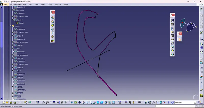
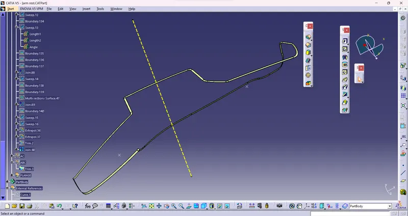
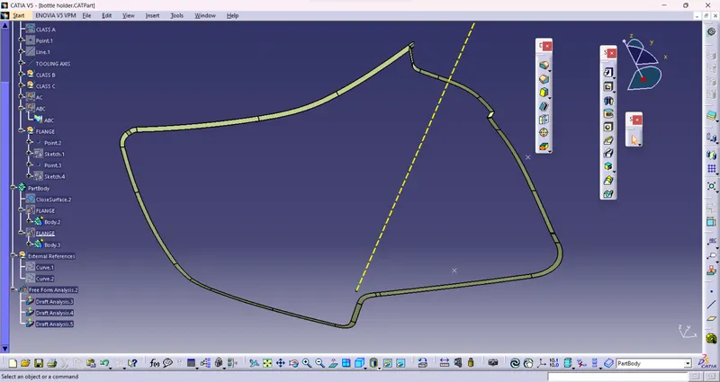
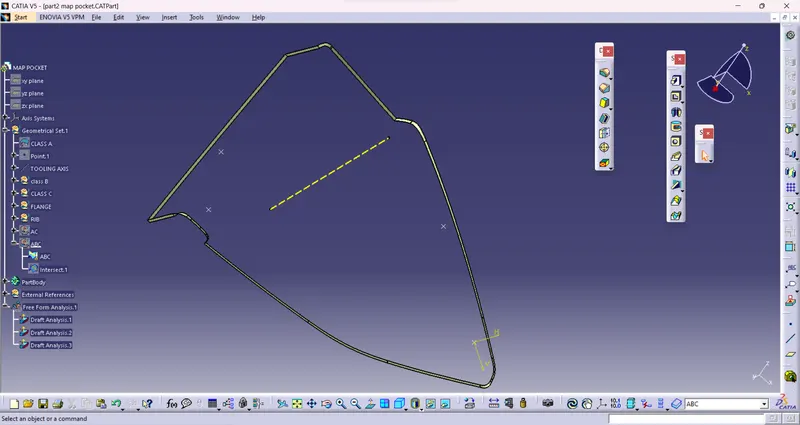
- The class A surface's boundary is taken as profile (guide curve) and then tooling axis created is taken as direction of the sweep in subtype draft direction
- The draft angle for the sweep is 3 degrees.
- The holes are created using the same axis and draft angle.
- The attained sweep is joined with class A surface to obtain the class C surface.
- The final trim is obtained by trimming the class B with the class C surface.
- The final check to ensure the proper clossness of surface with the boundary command .
LOWER SUBSTRATE
DOOR ARM REST
BOTTLE HOLDER
MAP POCKET
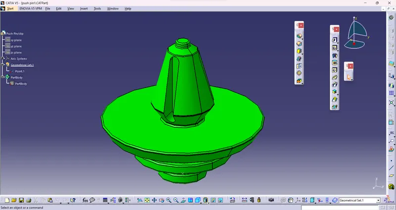
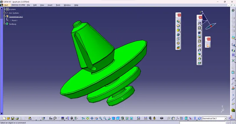
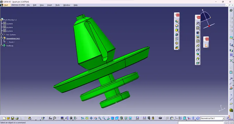
PUSH PINS
- These pins are used for the assembly purpose .
- These pins are guided into the sheet metal body.
- The pin is assembled over the dog house on one side and other into sheet metal.
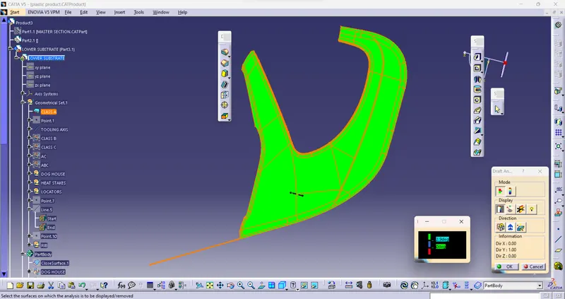
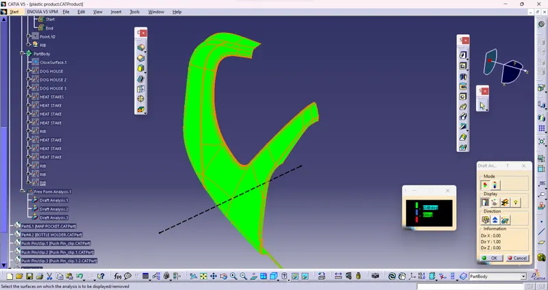
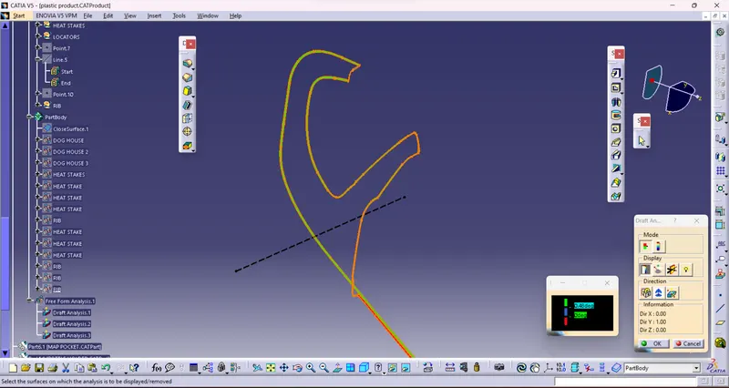
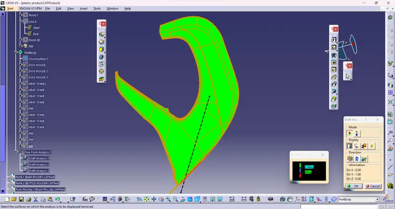
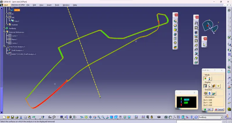
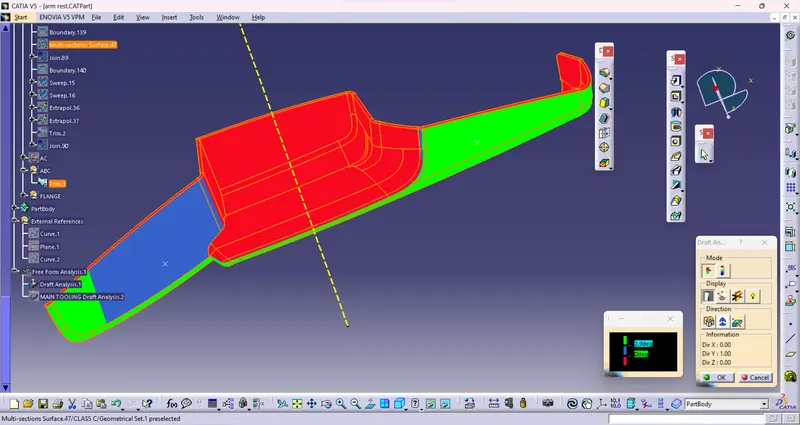
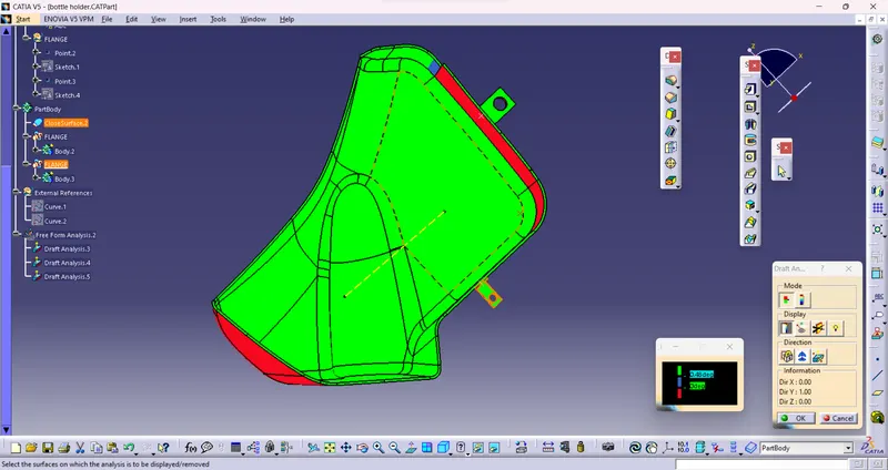
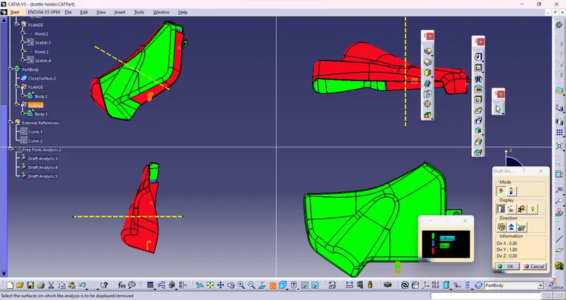
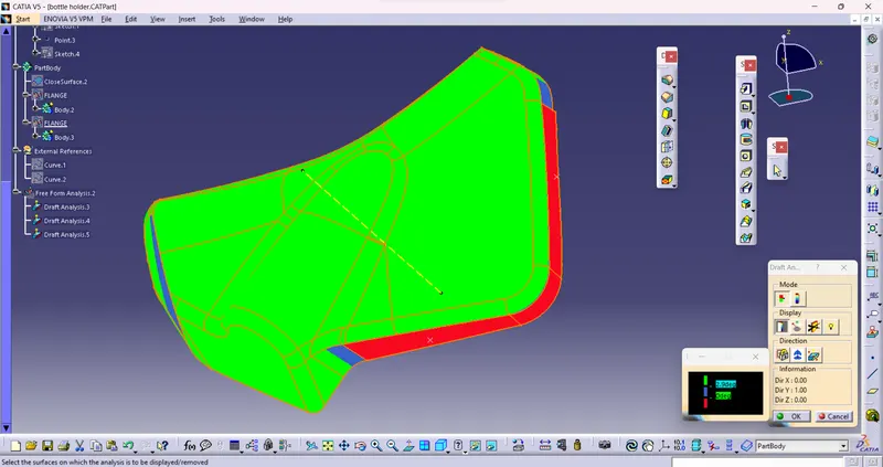
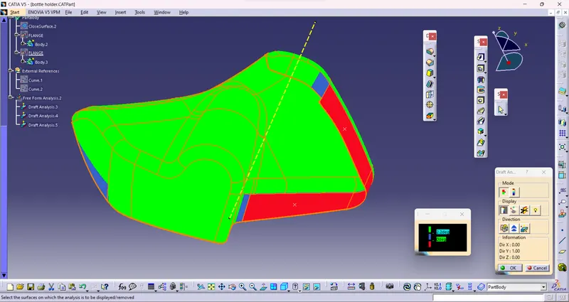
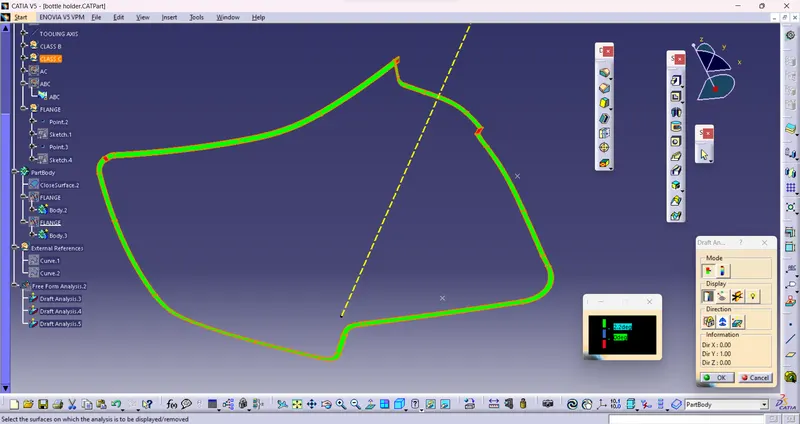
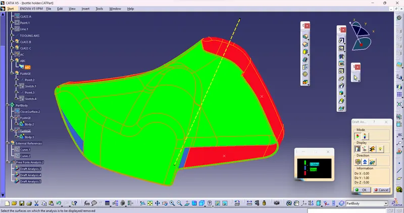
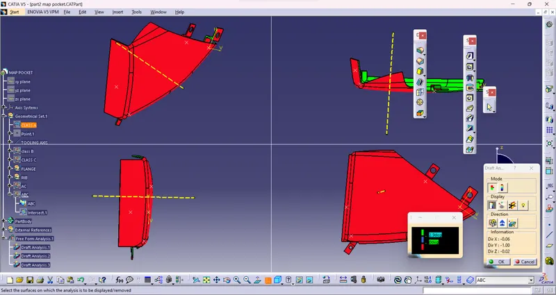
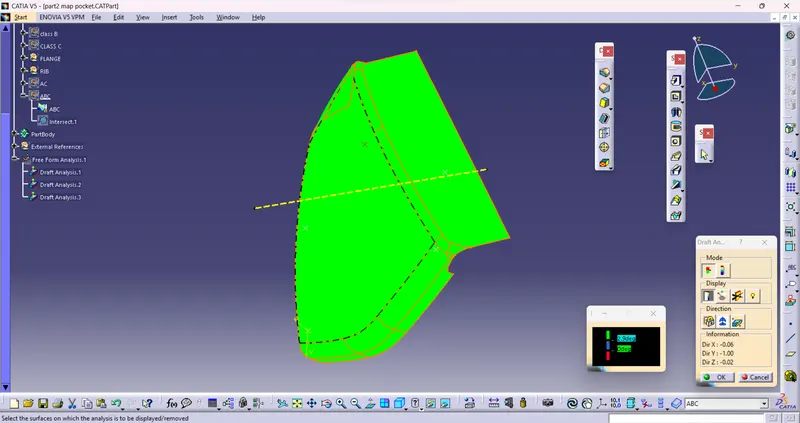
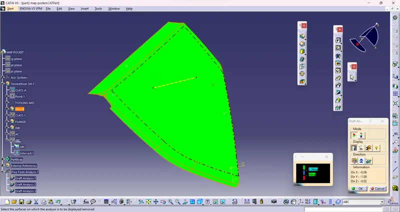
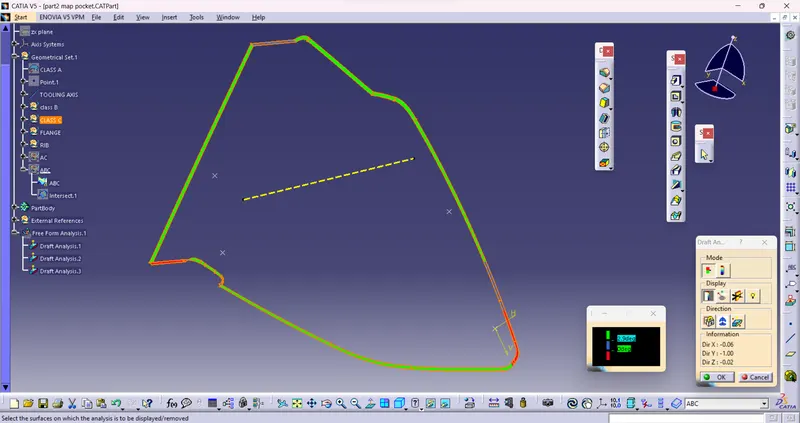
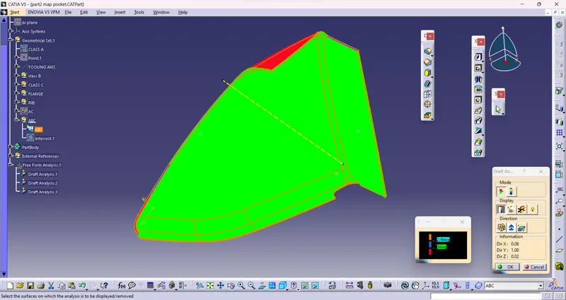
DRAFT ANALYSIS OF THE COMPONENTS
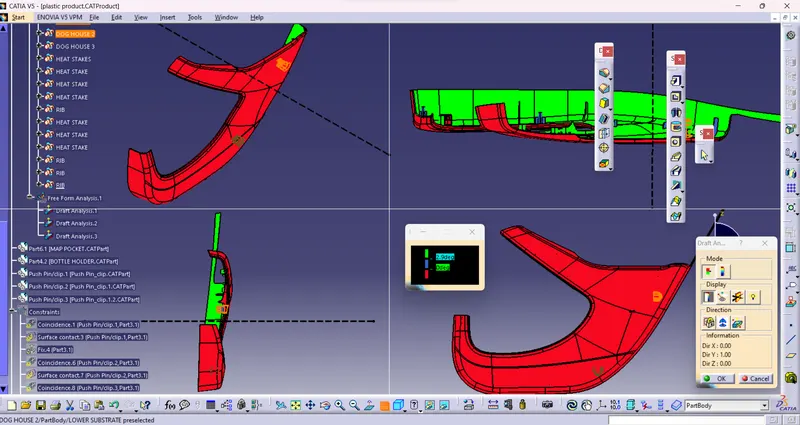
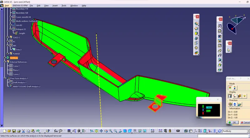
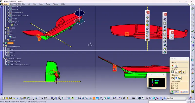
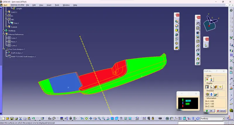
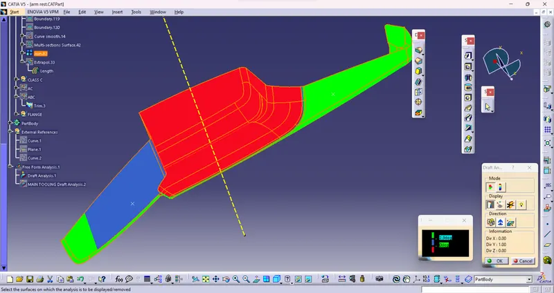
- The draft analysis is done to ensure that the draft in permeasible with the design consideration.
- The draft analysis is done by changing the visualization mode to customize and select shading as material.
- The draft based feature enables us to visualize and examine the draft.
- The draft window is has two tables one is for examining the draft and other one is the colour code.
- The draft value is set in the colour code window with each colour having their own significance.
- The red colour indicates the positive draft less than minimum draft where as the green colour indicates the minimum draft.
- The blue colour indicates the negative draft.
- For visualizing the draft the compass is aligned with the tool axis direction and the cursor is then made clicked upon the surface for viewing the draft.
- The quick view in display window enables to examine the draft value throughout the surface.
- Here both class A and closed body are given the minimum draft as 3 degrees.
- The attachment feature are given draft of 0.5 degrees.
LOWER SUBSTRATE
DOOR ARM REST
BOTTLE HOLDER
MAP POCKET
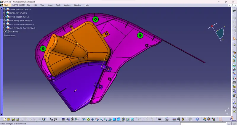
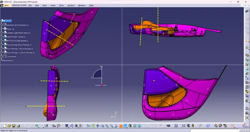
Assembly component :
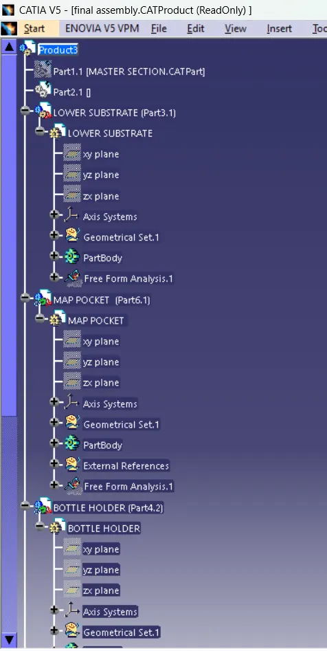
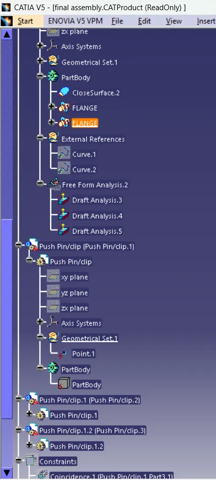
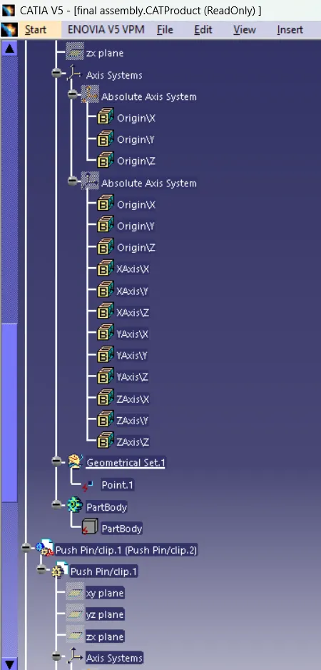
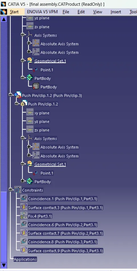
Tree structure :
conclusion
The door trim panel was sucessfully designed as per the OEM standards used in automotive industry in CATIA V5.