Section Modulus calculation and optimization
Section Modulus calculation and optimization
- Aim: Use the Section from your Hood design and calculate the section modulus using the formula S = I/y.
- From the below images, the steps for calculating the section modulus for the given surface can be seen. In order to see how actually the change in section modulus results in the behaviour of the material is it necessary to see what the section modulus actually is.
- Method:
- Section modulus:
- A "section modulus is the value of the "moment of inertia of area" related to the neutral axis of the cross-section of a beam multiplied by the distance from the neutral axis to the outer surface". Therefore, the relationship between the section modulus Z and the moment of inertia of area I is as expressed by the following equation.
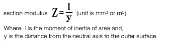
- The symbol Z is used customarily for the section modulus. In general, as the section modulus becomes larger, the strength against bending also becomes larger. Regarding bending, the maximum bending stress σ acting on the outer surface of the part can be calculated using the following equation.
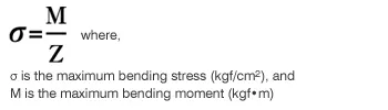
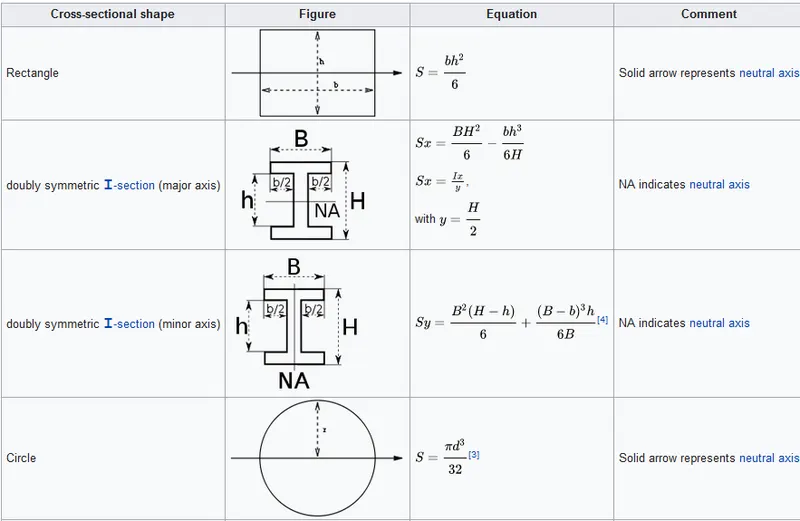
- Second moment of area or moment of inertia
- The second moment of area is also known as the moment of inertia of a shape. It is directly related to the area of material in the cross-section and the displacement of that area from the centroid. Once the centroid is located, the more important structural properties of the shape can be calculated. The axis that determines the centroid is also known as the neutral axis (N/A).
- The second moment of area is a measure of the 'efficiency of a shape to resist bending caused by loading. A beam tends to change its shape when loaded. The second moment of area is a measure of a shape's resistance to change.
- This picture contains the following scene. Diagram of a beam on its narrow edge supported at both ends. A man is walking on a straight beam. Diagram of a beam resting on its flat side supported at both ends. A man is walking on the straight beam and it is bending in the middle.
- Certain shapes are better than others at resisting bending as demonstrated in the diagram. Clearly, the orientation of the shape also influences bending.
First Design Study
The Intersection of the design was taken and then section Inertia Analysis was done-
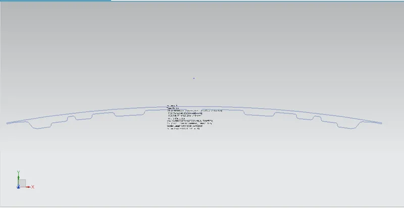
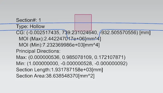
Moment of inertia(max) = 2.42247017e+06[mm^4]
Moment of inertia(min) = 7.232369986e+3[mm^4]
Y=873.5463/2=436.77315 mm
S=I/Y
S=7,232.369986/436.77315=16.559 mm^3
Hood Design Optimization
By increasing the depth of the inner panel by 0.5 mm
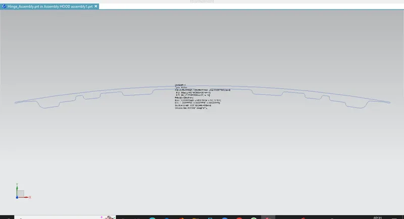
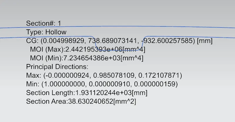
Here,
Moment of inertia(max) = 2.442195393e+06[mm^4]
Moment of inertia(min) = 7.234654386e+03[mm^4]
Y=873.5463/2=436.77315 mm
S=I/Y
S=7,234.654386/436.77315=16.5638 mm^3
Conclusion
So, here the difference can be seen in the moment of inertia and the change in the section modulus can be seen by the change in the design(depth).