Section Modulus calculation and optimization
ROOF:
They have given the outer panel where we have to do the design:
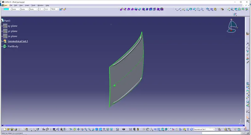
- Insert a Geometrical set & name it as Construction.
- Insert another geometrical set Outer panel under the construction.
OUTER PANEL:
- Intially Extract the surface.
- Next step is to Untrim the extracted surface.
- Insert a boundary for the Untrimed surface.
- Split the boundary with the Untrimmed surface.
- Sweep the Split.1\Edge.2 for 21mm & 3deg.
- Sweep the EdgeFillet.2\Edge.15 for 21.5mm & 70deg.
- Sweep the Split.1\Edge.4 for 20mm & 3deg.
- Sweep the Split.1\Edge.5 for 15mm & 25deg.
- Sweep the Sweep.4\Edge.6 for 45mm.
- Sweep the Sweep.5\Edge.7 for 60mm & 90deg.
- Sweep the Sweep.6\Edge.8 for 20mm & 50deg.
- Sweep the Sweep.7\Edge.9 for 20mm & 40deg.
- Sweep the EdgeFillet.2\Edge.14 for 21.5mm & 70deg.
- After finishing all the 9sweeps Extrapolate the sweep.1 surface with Edge1.
- Extrapolate the sweep.3 surface with Edge1.
- Trim the extrapolate 1 & extrapolate 2.
- Join split & trim.
- Edge fillet the join for 10mm.
- Insert a Multi Section Surface.
- Join sweep 2, sweep 9, edge fillet & multi section surface.
- Join sweep 4 To sweep 8.
- Extrapolate join 4.
- Trim join 2 & extrapolate 5.
- Extrude the trimmed surface for about 20mm with Y component.
- Extrapolate the extracted surface for about 93.5mm.
- Split the extrapolated surface with Trimmed surface.
- Apply edge fillet to splitted surface for 4mm.
- Apply the edge fillet for edge fillet 3 for 10mm.
- Apply the edge fillet for edge fillet 4 for 4mm.
- Apply the edge fillet for edge fillet 5 for 4mm.
- The blend corner Edge fillet Face 2 , face 3, & face 4 & st=et back for 5mm.
- Draw 2 planes.
- Intrsect blend corner & plane 1.
- Extract the blend corner edge 10.
- Insert a parallel curve for extract.3 surface.
- Split the Blend corner with parallel curve.
- Insert a corner for 4mm.
- Trim the parallel curve, corner, & intersect.
- Split the Blend corner with trimmed surface.
- Extrapolate the splitted surface.
- Insert a plane
- Split the extrapolated surface with plane 5.
- Symmety the plane & split.
- insert another plane.
- Finally Join the symmetry & split.
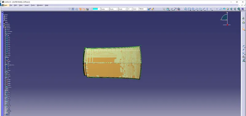
- Heat Distortion Has to be calculated according to rhe formulae given.
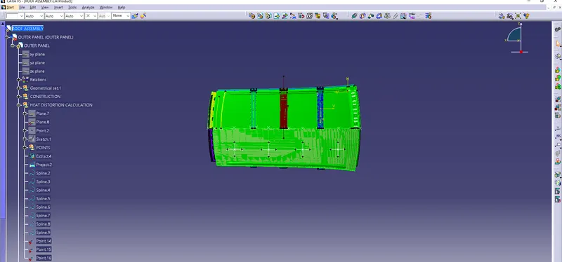
HEAT DISTORTION CALCULATION:
- Insert a geometrical set & name it as Heat Distortion Calculation.
- In this we have to calculate the heat distortion & the design has to be followed.
- Draw 2 planes Intially.
- Insert a point & Draw a sketch.
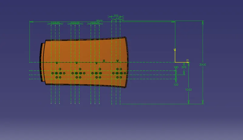
- After drawing the sketch we have insert 11 points.
- Then Extract the Join.6\Face.7 which is present in the outer panel.
- Select the projection command & project the sketch with support of extract.
- Insert 8 splines.
- Again insert 3 points
- Heat distotion is completed.
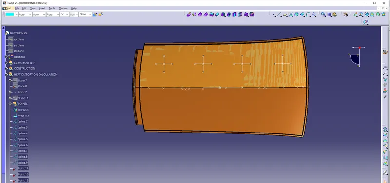
- Next Snow Load has to be designed.
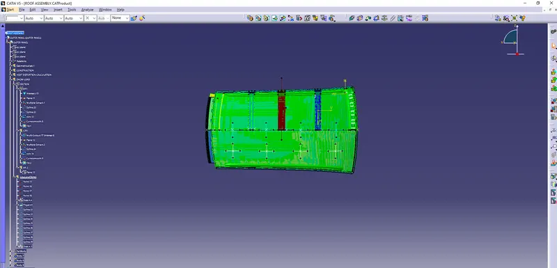
SNOW LOAD:
- Insert a geometrical set & name it as Snow Load.
- Inside the snow load insert another geometrical set & name it as section.
- Inside the section insert another 4 geometrical set & name it as BR1, CRR , BR2 & Calculation.
- The steps will be followed in BR1,BR2, CRR & calculation is shown in the design below .
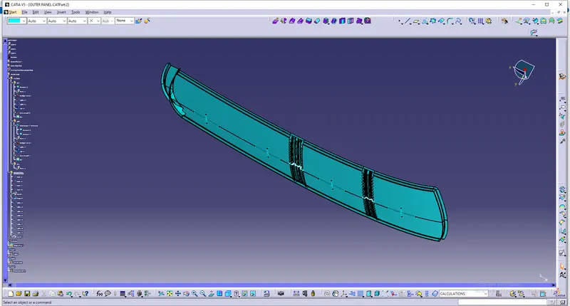
- Final product of outer panel.
FRONT ROOF RAIL:
- Insert a geometrical set Construction.
- Insert another geometrical set, Front Rails Panel, under Construction.
FRONT RAILS PANEL:
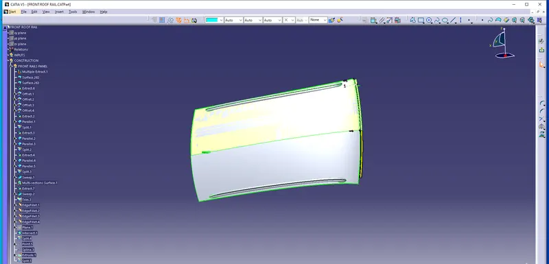
- Multiple Extract Surface.262\Face.2, Surface.263\Face.3
- Extract Surface.297\Face.7.
- Insert 3 offsets for the extracted surface for 32.75mm,5.5mm & 3.5mm.
- Insert another offset for Surface.262 for 1.5mm.
- Extract the offset 1.
- Insert the parallel curve for the extract2 with the support offset1 for 80mm.
- Split offset 1 with parallel curve1.
- Extract offset.2.
- Insert the parallel curve for extract3 with the support offset2 for 80mm.
- Insert the parallel curve for parallel2 with the support offset2 for 15mm.
- Split the offset2 with parallel curve 2 & 3.
- Extract the offset 3.
- Insert a parallel curve foroffset.3\Edge.9 with the support offset3 of 110mm.
- Insert a parallel curve fo extract4 with the support offset3 of 95mm.
- Split the offset3 with parallel curve 4 & 5.
- sweep it fo 36mm & 10deg.
- Design a multi section surface.
- Extract the split.3\edge.13.
- Sweep it for 10mm & 10deg.
- Trim everything from offset 4 to split 3.
- Edge Fillet trim3 for about 2.25mm.
- Edge Fillet , edge fillet 1 to about 5.75mm.
- Edge Fillet , edge fillet 2 to about 2.75mm.
- Edge fillet, edge fillet 3 to about 3.75mm.
- Draw a plane.
- Intersect edge fillet 4 & plane.
- Split edge fillet 4 with plane.
- keep a point.
- Insert a spline.
- Extrude the spline.
- Split split4 with extruded surface.
EMBOSSES:
- Insert a geometrical set under constrruction & name it as Embosses.
- Intially draw a plane.
- Draw a sketch.
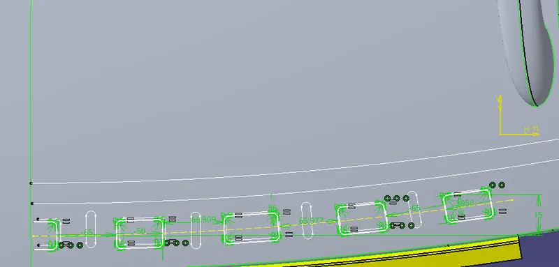
- Project the sketch with the support offset1.
- Split the split 5 with projected surface.
- Insert 5 sweeps for curve smooth for 12mm & 8odeg.
- Join all the sweeps with split 6.(join2)
- offset the split 1 for 10mm.
- Insert a parallel curve offset.5\edge.26 with support of offset5 for 10mm.
- Split offset 5 with parallel curve 6.(split7)
- Trim split 7 & join 2.(trim5)
- Edge Fillet the trim5 for 4mm.(edge fillet7)
- Draw a sketch.
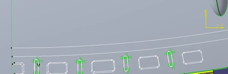
- Extrude the sketch for 20mm as Limit 1 & 69mm as Limit 2.
- Split edge fillet 7 with the extruded surface.(split 10)
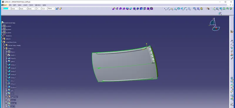
FINAL
- Create ageometrical set under construction as Final.
- Extrpolate split 10 with boundries edge1 for 15mm.(extrapolate3)
- Split extrapolate 3 with xy plane.(split11)
- Symmetry split 11 with xy plane.
- Join split aa with symmetry2.
- Final Front Roof Rail is designed
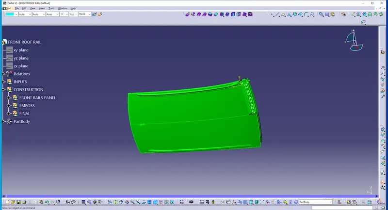
SOLID MODEL FOR FRONT ROOF RAIL:
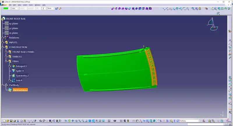
REAR ROOF RAIL:
- Insert a geometrical set Inputs.
INPUTS:
- Extract surface.1\face.1
- Extract surface.7\face.7
- Extract surface.8\face.8
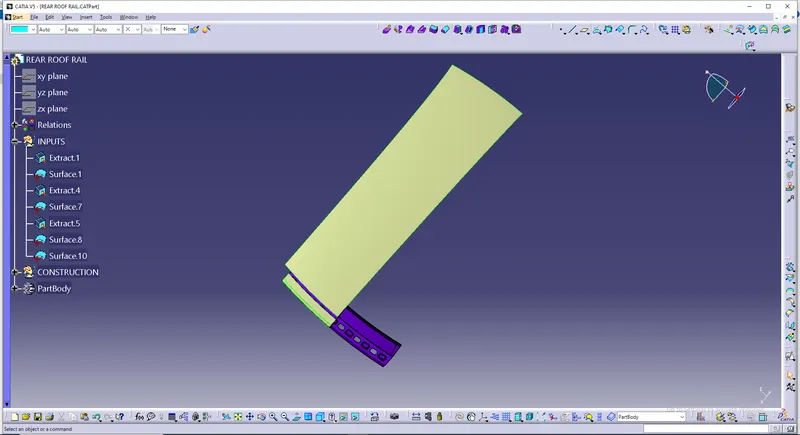
CONSTRUCTIONS:
- Insert a geometrical set construction.
- Insert a geometrical set under construction & name it as Rear Rail Panel.
REAR RAIL PANEL:
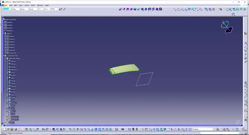
- Offset the Extract 1 surface for 1.5mm.
- Offset the Extract 4 surface for 91.5mm.
- Sweep offset.1\edge.8 with Y component for 70mm & 10deg.(sweep2)
- Expolate offset 2 with boundries edge1 for 88mm.(extrapolate2)
- Trim extrapolate 2 & sweep2.
- Insert parallel curve for curve Extract6 & support trim3 for 99mm.
- Split trim3with parallel curve 1.
- Sweep curve smooth 1 for 120mm & 32deg.(sweep 3)
- Offset the surface Extract4 of 4.5mm.(offset7)
- Offset the surface Extract4 of 6.5mm.(offset8)
- Trim offset 8 with sweep3.(trim4)
- Insert parallel curve for the curve Extract & support trim 4 for 10mm.(parallel2)
- Split trim4 with parallel2.
- Sweep curve smooth 2 for 10mm & 10deg.
- Trim offset 7 & sweep 4.
- Insert parallel curve for curve trim.5\curve.6 & support trim5 for 5mm.
- Split trim 5 with parallel 3.
- Join sweep1,2 & 3 with offset 1.
- Draw a plane.
- Split join 1 with plane2.
- Edge fillet split4 for about 4mm.
- Edge fillet , edge fillet 1 for about 2mm.
EMBOSSES:
- Create a point.
- sketch a plane.
- Draw a sketch.
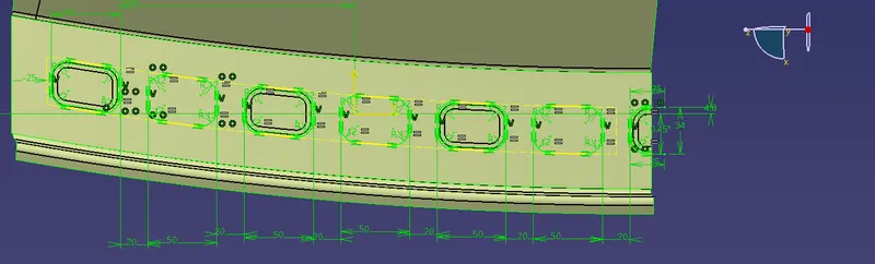
- Extrude the sketch Limit 1 for 20mm & Limit 2 for 24mm.
- Split edge fillet 2 with extrude 1.
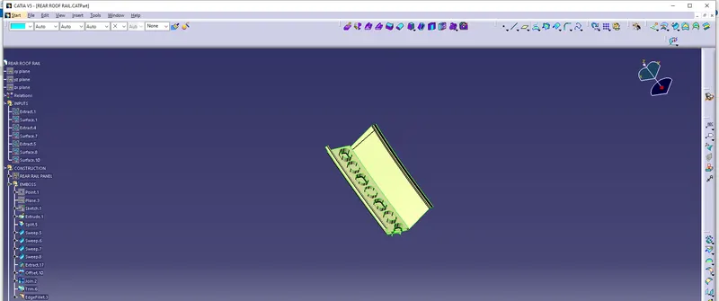
- 4 Sweeps for for extracts 12,13, 14 & 15 with split 5 for 12mm & 80deg.
- Extract edge fillet.2\face.18
- Offset extract 17for 10mm.
- Join all sweeps with split 5.
- Trim offset10 with join 2.
- Edge fillet the trim 6 for 4mm.
FINAL:
- Insert a geometrical set Final under the construction.
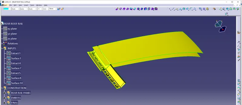
- Extrapolate edge fillet 3 with edge1.
- Split Extrapolate 3 with xy plane
- Symmetry split 6 with xy plane.
- Join split 6 & symmetry 1.
SOLID MODEL OF REAR ROOF RAIL:
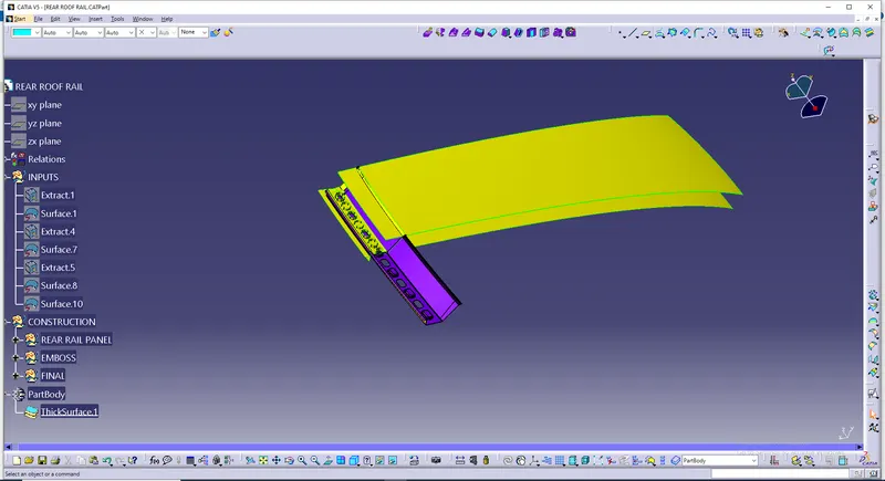
CENTRE ROOF RAIL:
- Insert a geometrical set Inputs.
- Extract the Surface 1.
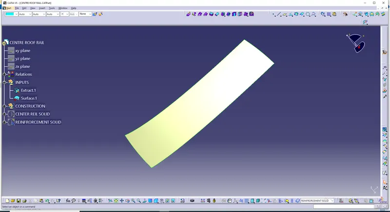
- Insert a geometrical set Constructions.
- Inside construction insert a geometrical set centre Rail Panel
CENTRE RAIL PANEL:
- Insert a point.
- Insert a parallel curve, curve as Extract.1\Edge.1 & support as Extract.1 for 1012mm.
- Insert a line.
- Project the line with the support of Extract.1
- Insert a parallel curve, curve as Project.1 & support as Extract.1 for 50mm.
- Insert a parallel curve, curve as Project.1 & support as Extract.1 for 50mm.
- Split Extract.1 with parallel 2 & parallel 3.
- Offset split 1 fo 6.5mm.
- Offset split 1 for 21.5mm.
- Insert a parallel curve offset.1\edge.2 & support as offset.1 for 18mm.
- Insert another parallel curve offset.1\edge.3 & support as offset.1 for 18mm.
- Split offset.1 with parallel curve 4.
- Split offset.1 with parallel curve 5.
- Sweep split.2\edge.4 with Y component for 23mm & 7deg.
- Sweep split.2\edge.5 with Y component for 23mm & 7deg.
- Trim offset.2 ,sweep.1 & sweep.2
- Insert a parallel curve Trim.1\Edge.1 & support of Trim.1 for 17mm
- Insert a parallel curve Trim.1\Edge.2 & support of Trim.1 for 17mm
- Split trim1 with parallel curve 6.
- Split trim1 with parallel curve 7.
- Insert 2 sweeps split.4\edge.6 with Y component & split.4\edge.7 with Y component for 23mm & 7deg.
- Offset split.1 for 16.5mm
- Trim sweep3, sweep4 & offset3.
- Joiin all split with trim.
- Edge fillet the join for 4mm
- Insert 2 points.
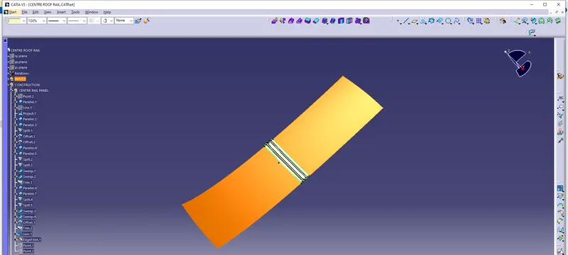
SIDE JOINT:
- Insert a geometrical set Side Joint inside the construction.
- Extract surface.3\face.3
- Project a Line.1 with support of extract.2
- Insert a parallel curve Project.2 With support of extract.2 for 50mm
- Insert a parallel curve Project.2 With support of extract.2 for 50mm
- Split Extract.2 with parallel curve 8 & parallel 9.
- Offset the split of 1.5mm.
- Insert a plane.
- Split edgefillet.1with plane.
- Add 2 splines.
- Multi section surface offset.12\edge.12 & Multple extract.1 with support offset .4 & split .7 reapectively with tangent continuity with both splines.
- Join split.7, multisection surface.1 & offset.4
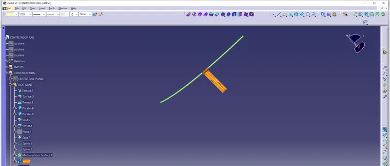
CUTOUT:
- Insert a geometrical set CutOut under construction.
- Draw a sketch.
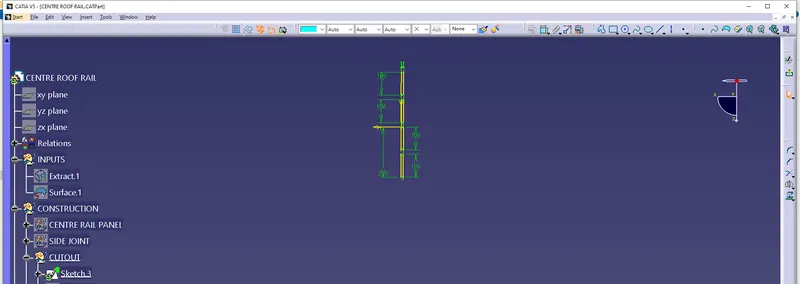
- Extrude the sketch.
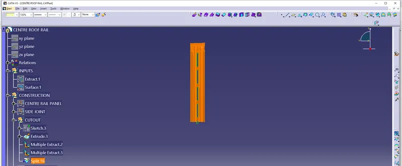
- Insert 2 multiple extracts for the extruded surfaces.
- Split the Join.2 with 2 multiple extracts.
FINAL:
- Insert a geometrical set Final.
- Extrapolate the Split.16 which is done in cut out, with edge.1
- Extrapolate the extrapolate.1 with edge.1
- Split the extrapolate2 with xy plane.
- Symmetry split.17 with xy plane.
- Join split.17 & symmetry.1
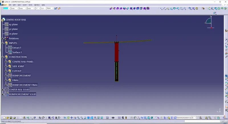
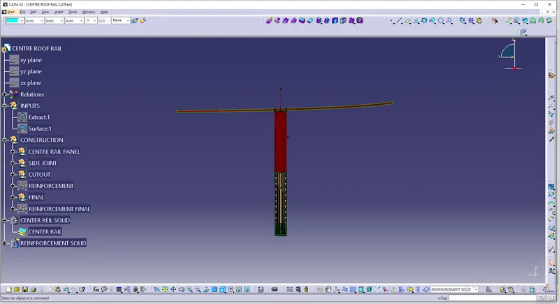
SOLID MODEL OF CENTRE ROOF PANEL:
BOW ROOF1:
- Insert a geometrical set Inputs.
- Extract the surface.
- Extract the curve 1.
- Extract the curve 2.
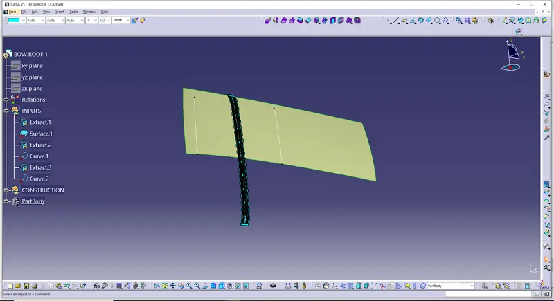
- Insert a geometrical set Constructions
- Insert another geometrical set Bow Roof Rail Panel under construction.
BOW ROOF RAIL PANEL:
- Intially Insert a point & a line.
- Project the line.1 with support extract.1
- Insert 2 parallel curves project .1 & support extract.1 for 40mm
- Split Extract.1 with 2 parallel curves.
- 2 Offsets for Split.1 for 6.5mm & 16.5mm
- Insert another 2 parallel curves offset.1\edge.2 & offset.1\edge.3 with the support offset.1 for 15mm
- 2 Splits offset.1 with Parallel curve 3 & parallel curve 4
- 2 Sweeps split.2\edge.4 & split.2\edge.6 with Y component for 20mm & 7deg
- Trim offset.2, sweep 1 & sweep 2.
- Insert 2 parallel curves trim.1\edge.1 & trim.1\edge.2 & support as trim.1 for 12mm
- 2 Splits trim.1 with Parallel curve 3 & parallel curve 4
- 2 Sweeps split.2\edge.7 & split.2\edge.8 with Y component for 20mm & 7deg
- Trim offset.3, sweep 3 & sweep 4.
- Join all the splits with the trim.2
- Edge fillet join 1 for 4mm.
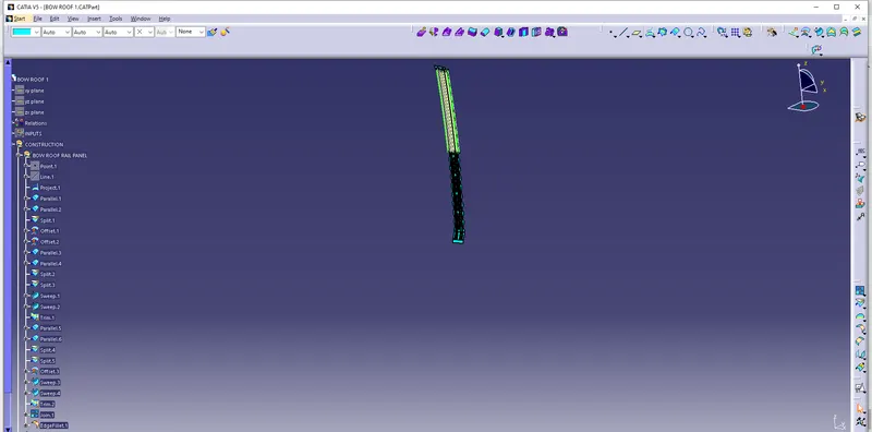
SIDE JOINT:
- Insert a geometrcal set Side Joint under construction.
- Extract Surface.3\Face.4
- Offset extract 4 for 1.5mm
- Project line.1with support offset4
- Insert 2 parallel curves Project.2 & support offset.2 for 40mm
- Split offset.4 with parallel curves 7 & 8
- Insert 2 splines.
- Insert a plane.
- Split edge fillet.1 with plane.1
- Multi section surface split.6\edge.17 & extract.6 with support split .6 & split .7 reapectively with tangent continuity with both splines.
- Join split.6 & split.7 with multisection surface.2
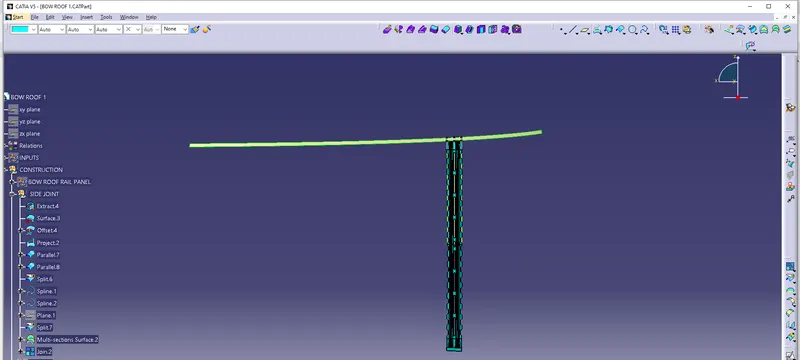
- Intially Insert a point & a line.
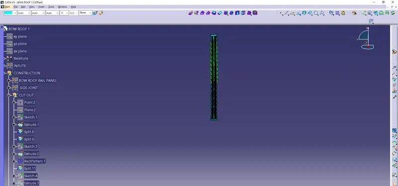
- Draw a sketch
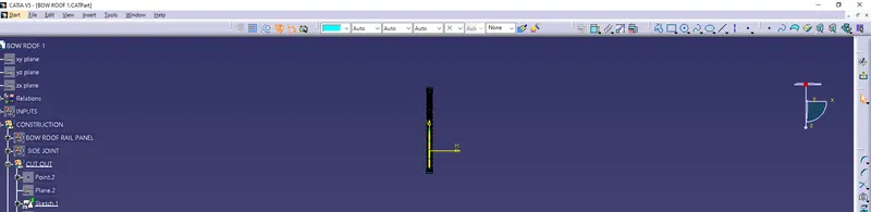
- Extrude the sketch , Limit 1 as 20mm & Limit 2 as 32mm
- Split join.2 with extrude 1
- Split join.2 with extrude 1 & extrude 3
- Draw a sketch.

- Extrude the sketch 3 , Limit 1 as 62mm & Limit 2 as 32mm.
- Put a Rectangular pattern 10instances 57 mm spacing, Reference element Z Axis & 2 objects.
- Split , split.8 with extrude.2 , extrude.3 & rectanfular pattern
FINAL:
- Insert a geometrical set Final under construction.
- Extrapolate split.11 with Boundary edge1 for 5mm
- Extrapolate extrapolate.1 with Boundary edge1 for 5mm
- Split extrapolate.2 with xy plane
- Symmetry split 12 with xy plane
- Join split 12 & symmetry.1 with merging distance 0.03mm.
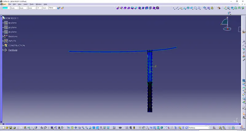
SOLID MODEL FO BOW ROOF:
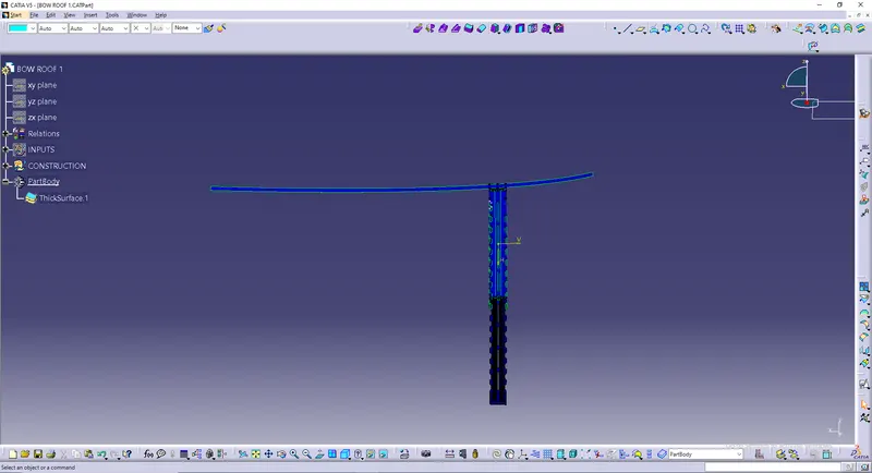
BOW ROOF 2:
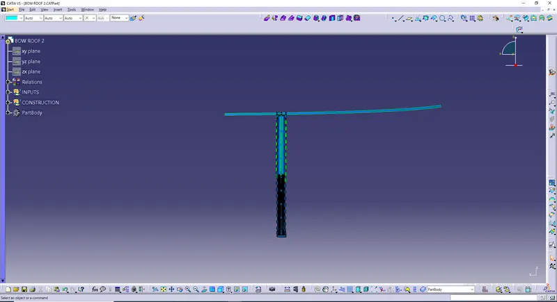
Same procedures followed in Bow Roof 2 as in Bow Roof 1
ROOF ASSEMBLY:
- Open Assembly Design & assemble everthing to get a ROOF assembly
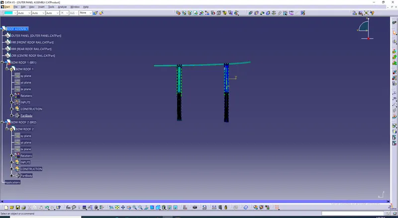
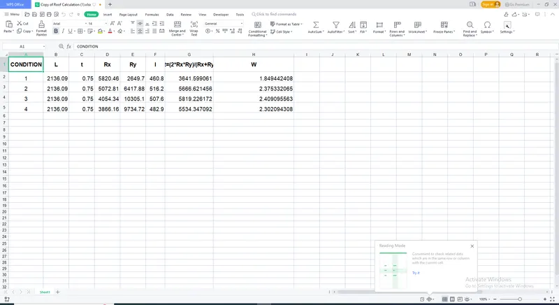
Calculation:
Your Assets
| Filname | Size | Action |
|---|---|---|
| ROOF AS…MBLY.zip | 11.48 MB |
Quick Links
Create a TicketRequest for One On oneRefer a FriendProfile Completion
25%