Section Modulus calculation and optimization
Section Modulus calculation and optimization of CAR HOOD(BIW closure)
INTRODUCTION
Section modulus is a geometric property of the cross section used for designing beams and flexural members. It does not represent anything physically.
To define section modulus, it may be defined as the ratio of total moment resisted by the section to the stress in the extreme fibre which is equal to yield stress.
AIM
The main obkective and aim of this section modulus calculation is to find find optimized section modulus value for the design of hood to find out the strength and makes optimized the design and data to finish high strength hood of a car
Section Modulus
In elastic bending, the stress distribution in the beam is as follows
As per theory of pure bending :
Where M= bending moment
I = moment of inertia of the section about the bending axis.
Sigma=fibre stress at a distance ‘y’ from the centroidal/neutral axis.
R = radius of curvature of the bent beam.
E = Young’s Modulus of the material of the beam.
If y is replaced by c, the distance to remotest element, from the neutral axis or centroidal axis, then
Where, Z= section modulus and is given by
This Z is the elastic section modulus used for elastic design for beam. It is usually denoted by Ze.
When the stress distribution in the beam becomes plastic, the analysis changes.
In the case of plastic bending:
The stress distribution within a cross section in plastic bending is:
Moment resisted by a section that has attained full plasticity is given by:
M = Fy* (A/2) * ( Yc +Yt )
Where,
M = Moment
Fy = Yield stress
A = Area of the cross section
Yc = distance of centre of area under compression from equal-area axis.
Yt = distance of centre of area under tension from equal-area axis.
Now,
M = Fy* (A/2) * ( Yc +Yt )
Zp = M/Fy.
Hence,
Zp = (A/2) * ( Yc +Yt )
This is the plastic section modulus and may be used for the plastic design of beams.
For the same section, the plastic and elastic modulus are different. The difference in their values indicates the reserve in strength or moment resisting capacity that a section made from sufficiently ductile material possesses. The ratio between plastic and elastic section modulus is known as shape factor. The more is the value of shape factor the more is the reserve strength in the section on attaining plasticity.
Shape factor = Plastic modulus/ Elastic modulus
It can be intuitively seen that as more and more material is concentrated near centre or equal-area axis (as in circular or rhombus section) the value of shape factor increases and as more and more material is concentrated away from centre or equal area axis (as in I section) the value of shape factor decreases.
SECTION MODULUS CALCULATION
The section modulus calculation is to be done for hood design in NX CAD .The ultimate Aim is to be to get a optimized value for section modulus
Higher value of section modulus calculation leads to high strength of HOOD
CALCULATION
S=I/Y
S=Section Modulus
I=Moment of inertia
Y=Distance Between neutral axis to extreme end of the object
For this section modulus optimization we consider two cases which default data and optimized data
CASE 1
With use of NX CAD taking a area moment inertia value for intially designed value
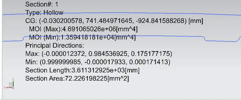
From the above given data
Moment of inertia (MAX) = 469106.5026mm*4
Moment of inertia (MIN) = 135941.8181mm*4
S=I/Y
Where Y value is Y=D/2
D=870.9 /2
=435.45mm
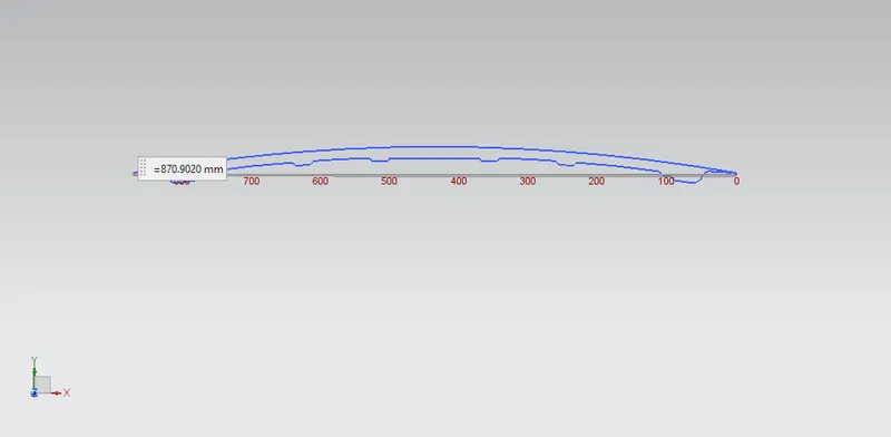
S=135941.8181/435.45
Section modulus for intial case =312.1869746mm*3 ........................................................(1)
CASE 2 OPTIMIZED VALUE
since when compared with intial value of date the second case is optimized data which the area is to be increased for section modulus
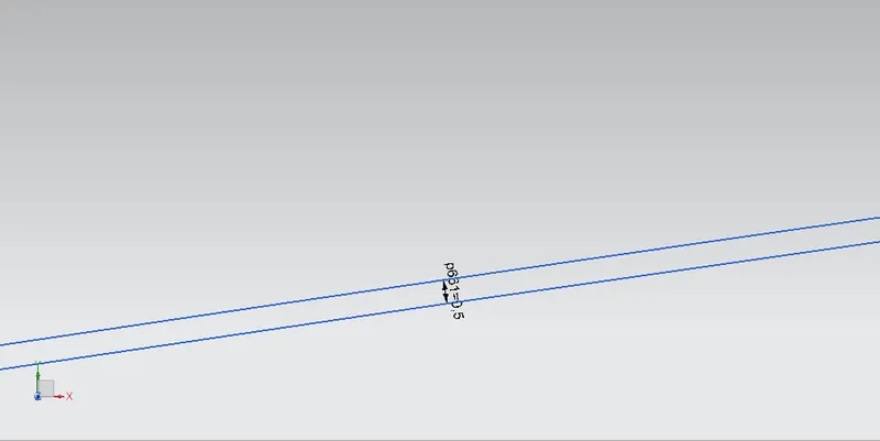
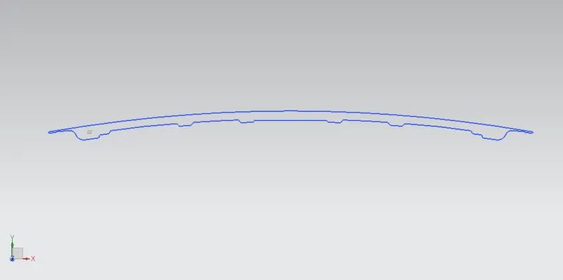
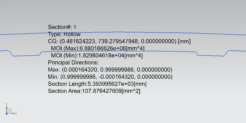
From the above given data
Moment of inertia (MAX) = 688016.6626mm*4
Moment of inertia (MIN) = 182980.4618mm*4
S=I/Y
Where Y value is Y=D/2
D=870.9 /2
=435.45mm
S=182980.4618/435.45
Section modulus for optimized case =420.2100397mm*3 ........................................................(2)
CONCLUSION
While comparing the both result value of case 1 and case 2 the case 2 optimized value as high section modulus value has more strength provided to hood .
At end the the section modulus value has to be increased for the hood design .