Radar Mast & Final Assembly of Yacht
SURFACE MODELLING OF SUNSEEKER PREDATOR YACHT ASSEMBLY AND RENDER
.
ABSTRACT
The main abstract of this project is to be create a sunseeker predator yacht by using solid works CAD tool. It includes part modeling, surface modeling assembly and realistic render
INTRODUCTION
Sunseeker International is a British luxury performance motor yacht brand. Originally named Poole Power Boats, the company was founded by brothers Robert and John Braithwaite in 1969. The company changed its name to Sunseeker International in 1985 and has since become a global icon.
In this project we have to make a predator yacht type model as reference we finish a complete model using surface tools in solid works it also covers with complex curves , part designing, advanced curve handling ,projected curves , 3d sketch with professional surface handling . The sketches, dimensions, constraints are to be applied to get finished yacht completely . The design approach used here is parametric based feature modeling which is very handy modeling which doesn’t have complex process . In end of this to make a assembly of complete yacht as per guidelines with realistic render using photoview 360 and solid works visualize
OBJECTIVE
The yacht modeling has objective of making complete predator yacht. The objective start with part modeling of yacht in the part modelling phase it has to model the additional parts of yacht other than surface modeling of yacht in part modeling came to know about usage of features and sketches and learn about how to achieve complex shapes in solid modeling . The second phase of design is surface design which is a power features to achieve complex and organic shapes in yacht. The surface tools have a specific guide lines to follow which are concentrate on continuity of curves in smooth manner, surface doesn’t under goes any gap to achieve a class A surface . The features like knitting, surface fill are used to achieve this guide lines
In end of the part modelling and surface modelling the assembly phase is started its followed to make complete assembly of yacht
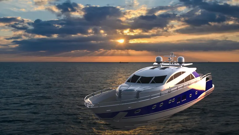
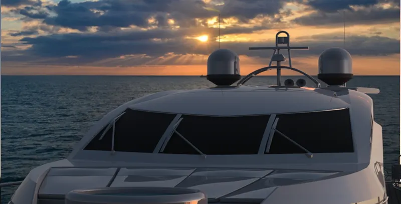
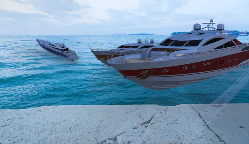
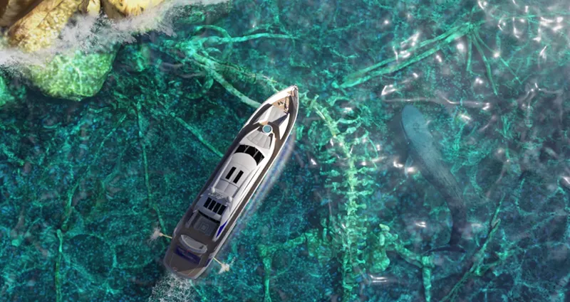
The final phase of the modeling is to make a complete and realistic rendering of yacht using photo view 360 in inside solidworks and solidworks visualize which is a standalone tool used for rendering
METHODOLOGY AND PROCESS
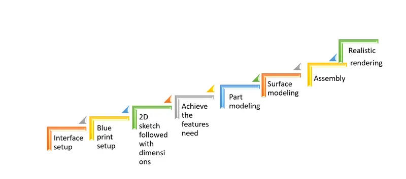
THREE PHASES OF YACHT MODELING
- Part modeling
- Surface modeling
- Assembly and Realistic rendering
BLUE PRINT SETUP
Blue print setup is the initial step of hull modeling
Methodology
Insert the blue print in separate planes and rename it as per plane
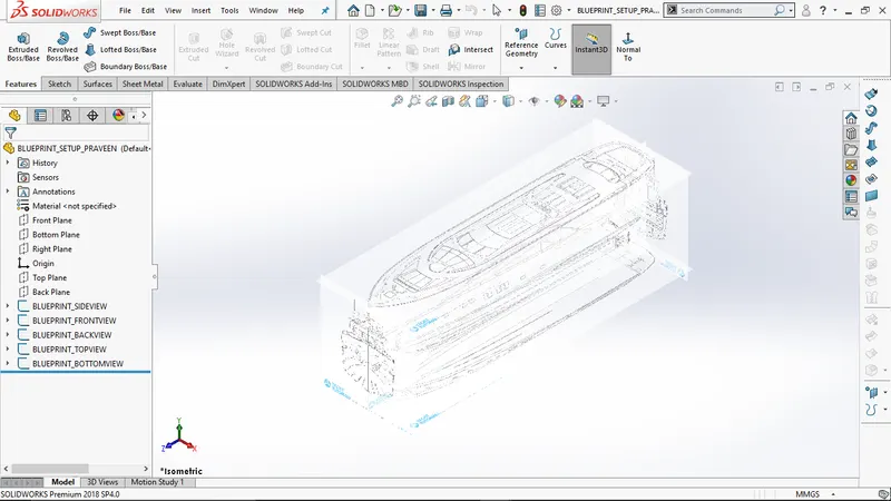
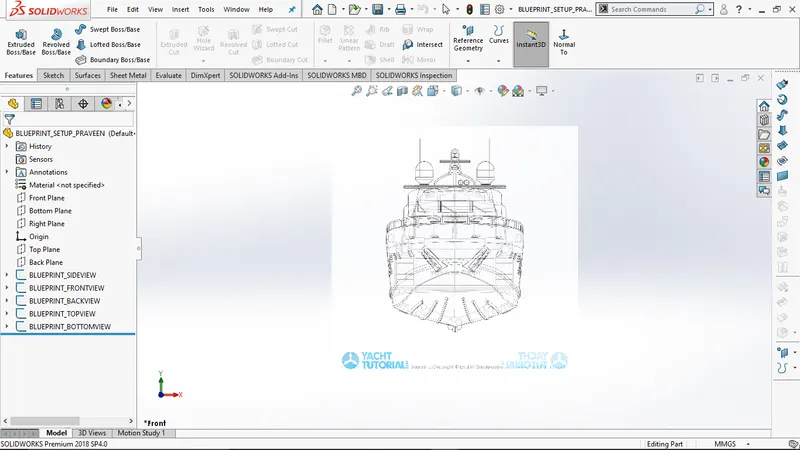
TOOLS USED IN PART MODELLING AND SURFACE MODELLING :
2D Sketch
It is used to create two dimensional drawings in the selected view of plane
3D Sketch
3D sketch is a three dimensional as in the define it is used to make sketch in any plane
with out selecting specific plane
Line
Line tool creates a straight line and tangent arcs
Circle
Circle tool used to create a circle in respective plane
Rectangle
Tool used to make rectangle there are three types rectangle .
Spline
Spline is a more power full tool in solid works is used to make curves and splines as per
required
Arc
Three types of arcs are available center point arc etc . used to draw a arc as per drawing
Fillets
Fillet is used to make a sharp edges to round edges
Chamfer
Chamfer is used to make a chamfering the sharp corners
Slots
Slots are two types used to make round corner rectangles
Trim
Trim tool used to trim the excess lines it has specific types of features are included power trim etc.
Convert entities
Convert entities is used to make sketch from another sketch to the respected plane
Offset entities
Offset entities is to make sketch offset from specified distance
Dynamic mirror
Dynamic mirror used to mirror the entire feature of the plane selected for mirroring
Extent entities
It is used to extend the end point lines to make closed sketch
PART MODELING PHASE
FEATURES USED IN PART MODELING
Extrude boss/ base
Extrude a 3d solid feature from respected geometry
Revolved Boss/Base
To create a solid feature, a sketch or its selected contours are revolved around an axis.
Lofted Boss/Base
To create a solid feature, it adds material between two or more profiles.Fillet
Fillet is used to make round corner instead of sharp corner extruded by feature
Extruded Cut
Extrude cut is used to reduce the area as per sketch in linear manner as followed by sketch
Circular Pattern
Its like copying specific feature are bodies in circular pattern
Sketch Driven Pattern
Making feature copying as pattern in the drawn sketch
Mirror
Mirror is used to make a selected feature or body but it need a reference plane or axis for Mirroring
Split Line
It projects a sketch to curved or planar faces, creating multiple separate faces.
Chamfer
It creates a transitional edge at the intersection of two sketch entities when used as a sketch
tool. When used as a feature, it creates a bevel feature along an edge or a vertex.
Plane
Plane is additionally created by reference of existing one for achieved the proportions
Dome
This creates a dome shape to the selected face
Helix and Spiral
Adds a helix or spiral curve from a sketched surface.
Linear Pattern
It creates a pattern of features, faces and bodies in one or two linear directions.
Shell
A thin-walled feature is created using Shell which removes material from the selected solid body.
Curve driven pattern
Curve driven pattern is same as linear pattern it follows a curve
MODELS MODELED UNDER PART MODELING
- Propeller
- Radar
- Garage door
- Radar Mast
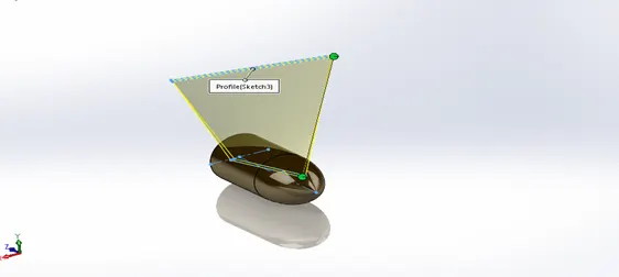
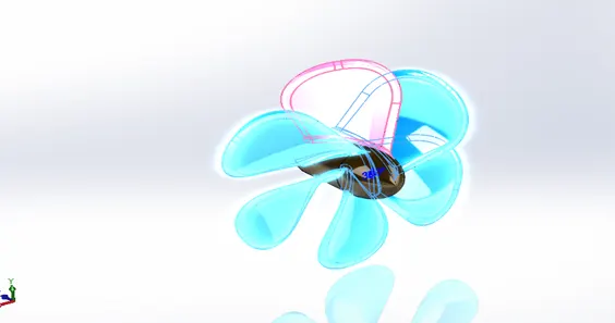
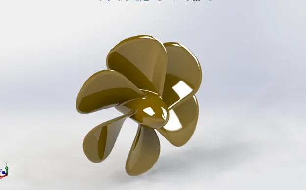
PROPELLER
Description:
“Propeller is a locomotive mechanism in ships used to create a thrust for ship to move forward . the power from main engine transmits it power to propeller blade based on speed and direction of rotation decides movements of the ship”
Tools used
- Line
- Arc
- Plane
- Trim
Constraints used
- Midpoint
- Coincident
- Vertical
- Horizontal
Features used
- Revolve
- Extrude boss/bass
- Loft
- Fillet
- Shell
- Circular pattern
Methodology
As plane reference making sketch as followed the dimension and proceed the required features
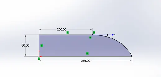
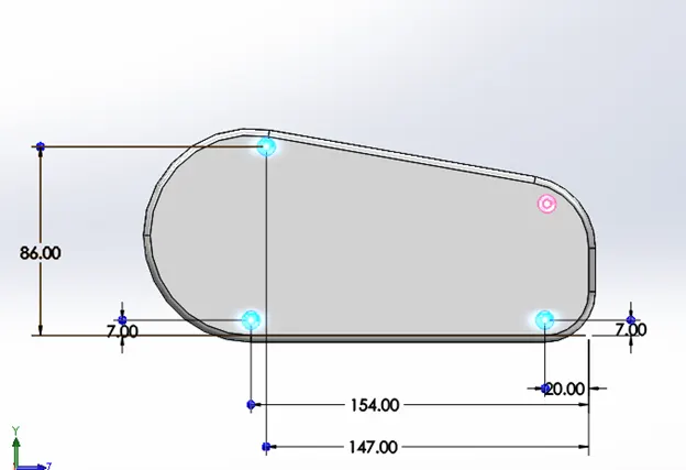
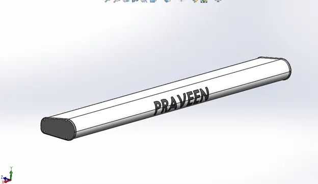
RADAR
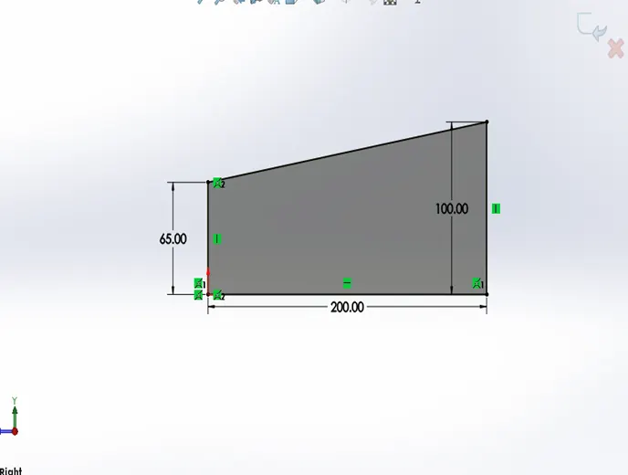
Description :
“Radar is electro magnetic sensor used for detecting, locating, tracking, and recognizing objects of various kinds at considerable distances. It operates by transmitting electromagnetic energy toward objects, commonly referred to as targets, and observing the echoes returned from them. The targets may be aircraft, ships, spacecraft, automotive vehicles, and astronomical bodies, or even birds, insects, and rain.”
Tools used
- Line
- Arc
- Slot
- Polygon
- Text
Constraints used
- Midpoint
- coincident
Features used
- sketch driven pattern
- Extrude boss / bass
- Fillet
- Chamfer
- Extrude cut
Methodology
As plane reference making sketch as followed the dimension and proceed the required features
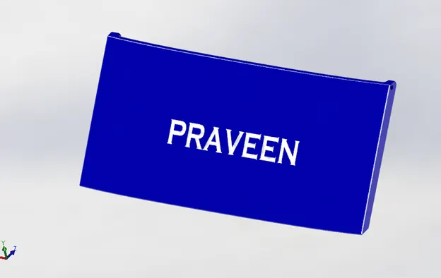
GARAGE DOOR
Description:
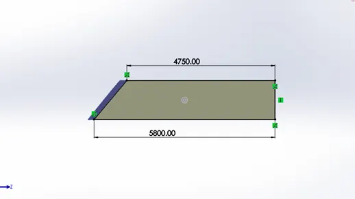
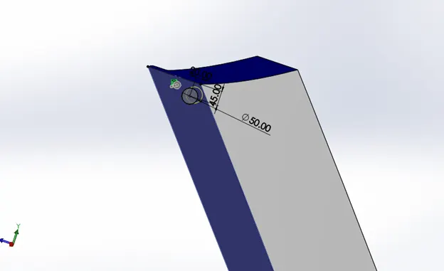
“Garage door is used to close the garage in yacht garage is use to store essential things need for dive the door that used to close the garage in yacht is known as garage door”
Tools used
- Line
- Arc
- Spline
- Text
Constraints used
- Midpoint
- Perpendicular
- Horizontal
- Vertical
Features used
- Extrude boss/bass
- Extrude cut
- Fillet
- Chamfer
- Mirror
Methodology
The garage door is making the reference part that is split from the part hull as with the reference of the split part
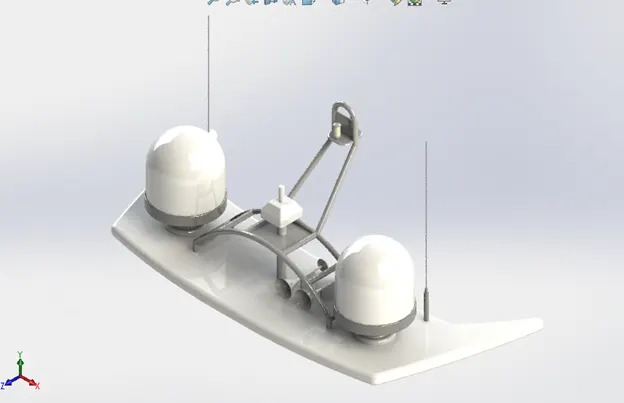
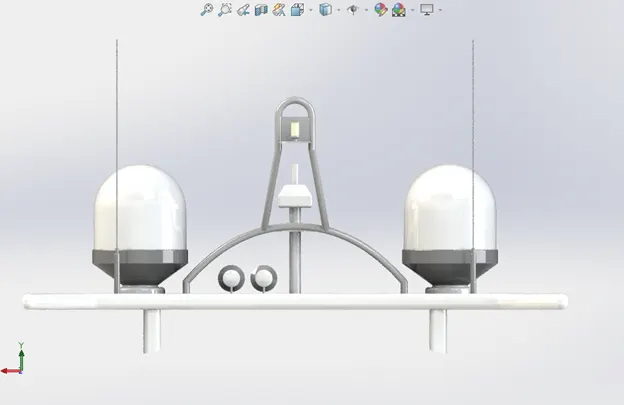
RADAR MAST
Description
“Radar mast is structure rising above the hull and upper portions of a yacht to hold radar and other supportive devices ”
Tools used
- Line
- Spline
- Circle
- Rectangle
- Arc
- Offset entities
- Trim
Constraints used
- Vertical
- Horizontal
- Coincident
- Midpoint
- Perpendicular
- Parallel
Features used
- Extrude boss/bass
- Revolve boss/bass
- Projected curve
- Sweep
- Extrude cut
- Mirror
- Fillet
- Shell
- Dome
- Combine
Methodology
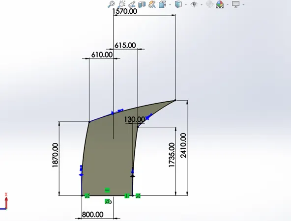
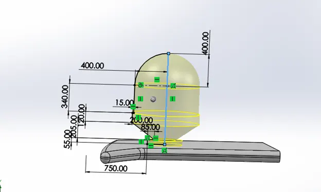
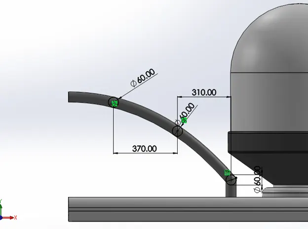
Extrude with superstructure surface as reference in given dimension followed with further geometry constraints to complete the radar mast
SURFACE MODELING PHASE
Features used in surface modeling
Projected Curve
Projected curve which is created with integrations of two sketches and makes a new curve
Lofted Surface
Creates a lofted surface between two or more profiles.
Trim Surface
Trim surface is used to trim surfaces which each intersect with each other with one reference surface is trim
Extruded Surface
Creates an extruded surface from the sketch.
Swept surface
It is used to extrude surface follow with guide lines
Knit Surface
It make a surface into integrated one which two different surfaces knitted together without gap
Filled Surface
Constructs a surface patch within a boundary defined by existing model edges, sketches, or curves.
Shell
A thin-walled feature is created using Shell which removes material from the selected solid body.
Revolved Boss/Base
To create a solid feature, a sketch or its selected contours are revolved around an axis.
Lofted Boss/Base
To create a solid feature, it adds material between two or more profiles
.Fillet
Fillet is used to make round corner instead of sharp corner extruded by feature
Extruded Cut
Extrude cut is used to reduce the area as per sketch in linear manner as followed by sketch
Circular Pattern
Its like copying specific feature are bodies in circular pattern
Sketch Driven Pattern
Making feature copying as pattern in the drawn sketch
Mirror
Mirror is used to make a selected feature or body but it need a reference plane or axis for Mirroring
Split Line
It projects a sketch to curved or planar faces, creating multiple separate faces.
Chamfer
It creates a transitional edge at the intersection of two sketch entities when used as a sketch
tool. When used as a feature, it creates a bevel feature along an edge or a vertex.
Dome
This creates a dome shape to the selected face
Helix and Spiral
Adds a helix or spiral curve from a sketched surface.
Linear Pattern
It creates a pattern of features, faces and bodies in one or two linear directions.
Shell
A thin-walled feature is created using Shell which removes material from the selected solid body.
Delete Face
Deletes faces from solid bodies to create surfaces, or deletes faces from surface bodies.
MODELS MODELED UNDER SURFACE MODELING
- Hull
- Front seat
- Rear seat
- Middle seat
- Super structure
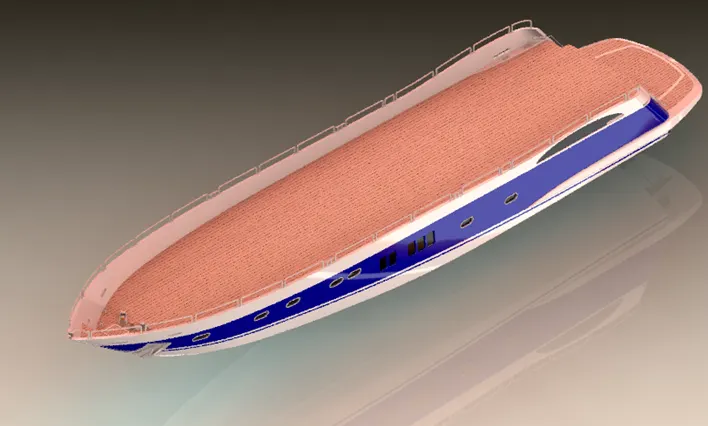
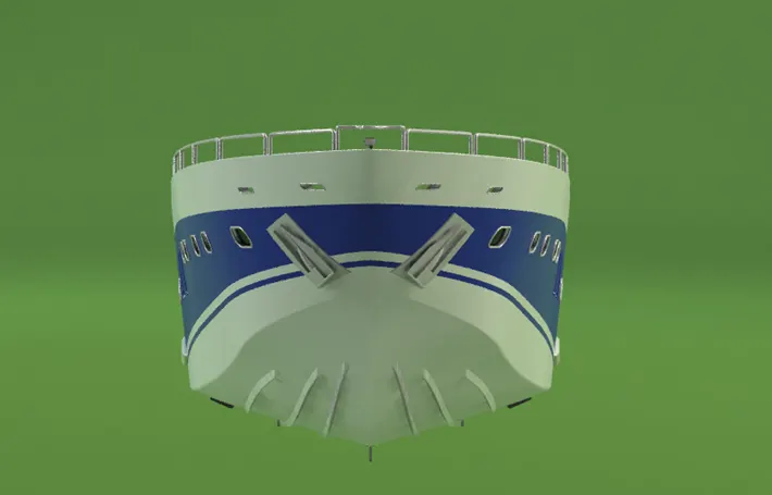
HULL
Definition
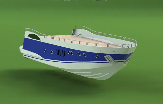
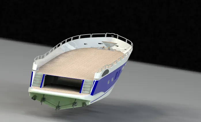
A hull is the watertight body of a yacht. The hull open at the top fully or partially covered with a deck. A top the deck superstructures are fixed .
Tools used
- Line
- 3D sketch
- 2D sketch
- Rectangle
- Spline
- Circle
- Straight slot
- Smart dimensions
- Convert entities
- Offset entities
- Copy/Move entities
Constraints used
- Vertical
- Horizontal
- Coincident
- Perpendicular
- Pierce relation
- Tangent
- Colinear
- Parallel
Features used
- Projected Curve
Projected curve which is created with integrations of two sketches and makes a new
curve
- Lofted Surface
Creates a lofted surface between two or more profiles
- Trim Surface
Trim surface is used to trim surfaces which each intersect with each other with one
reference surface is trim
- Extruded Surface
Creates an extruded surface from the sketch
- Knit Surface
It make a surface into integrated one which two different surfaces knitted together
without gap
- Filled Surface
Constructs a surface patch within a boundary defined by existing model edges,
sketches, or curves.
- Shell
A thin-walled feature is created using Shell which removes material from the selected
solid body.
- Extruded Boss/Base
This feature extrudes an entire sketch or its selected contours in one or both directions
- Extruded Cut
Extrude cut is used to reduce the area as per sketch in linear manner as followed by
s sketch
- Fillets
Fillet is used to make a sharp edges to round edges
- Chamfer
Chamfer is used to make a chamfering the sharp corners.
- Plane
A reference plane is added based on the selection of references as per the requirement of our sketch
- Swept Boss/Base
Sweeps a closed profile along an open or closed path to create a solid feature.
- Revolved Boss/Base
To create a solid feature, a sketch or its selected contours are revolved around an axis.
- Dome
This creates a dome shape to the selected face
- Helix and Spiral
Adds a helix or spiral curve from a sketched surface.
- Linear Pattern
It creates a pattern of features, faces and bodies in one or two linear directions.
- Mirror
Mirror is used to make a selected feature or body but it need a reference plane or axis
for Mirroring
- Split Line
It projects a sketch to curved or planar faces, creating multiple separate faces.
Methodology
The hull which start from initial blue print which extrude the outer hull model and it as to sculpt the all the features including
Stairs
Anchor
Side railings
Garage
Anchor holding mechanisms
Windows
Propeller power transmitters
Etc.
Super Structure
Description
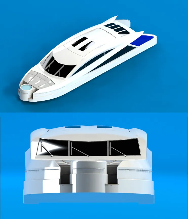
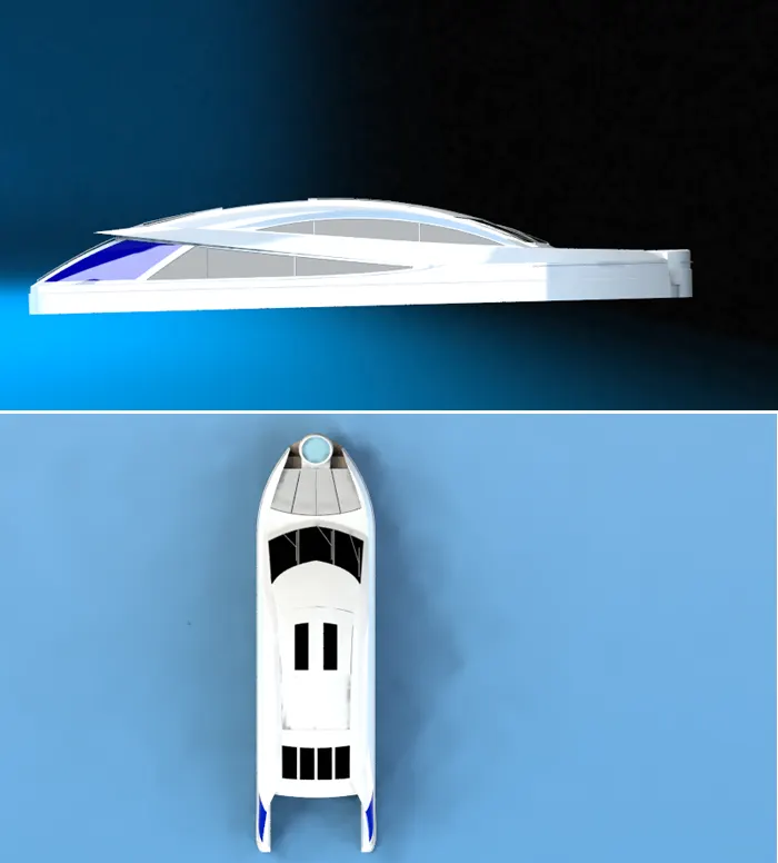
A superstructure is an upward extension of an existing structure above a hull
Tools used
- Line
- 3D sketch
- 2D sketch
- Rectangle
- Spline
- Circle
- Straight slot
- Smart dimensions
- Convert entities
- Offset entities
- Copy/Move entities
Features used
- Extruded Surface
Creates an extruded surface from the sketch
- Plane
A reference plane is added based on the selection of references as per the requirement
of our sketch
- Swept Surface
Creates a surface feature by sweeping an open or closed profile along an open or closed path
- Knit Surface
It make a surface into integrated one which two different surfaces knitted together
without gap
- Fillet
Fillet is used to make round corner instead of sharp corner extruded by feature
- Ruled Surface
Inserts ruled surfaces from edges.
- Trim surface
Trim surface used to trim the surface which make intersection on another surface
- Projected curve
Projected curve makes curve which is intersection of curves on two different plan
- Lofted surface
Lofted surface creates a loft surface on two or more selected surfaces
- Filled surface
The edges of the surface as reference the surface is to fill
- Extend surface
Extend surface used to extend the surface based on sketch drawn
- Extrude boss/ base
Extrude a 3d solid feature from respected geometry
- Extruded Cut
Extrude cut is used to reduce the area as per sketch in linear manner as followed by
sketch
- Delete face
Delete face used to delete the selected face
- Offset surface
Surface tool used to offset the selected distance as per given dimensions
- Thicken
It thicken the already knitted surface
- Dome
This creates a dome shape to the selected face
- Split Line
It projects a sketch to curved or planar faces, creating multiple separate faces.
- Mirror
Mirror is used to make a selected feature or body but it need a reference plane or axis
for Mirroring
- Chamfer
It creates a transitional edge at the intersection of two sketch entities when used as a
sketch tool. When used as a feature, it creates a bevel feature along an edge or a vertex.
- 3D sketch
Used to draw any planes vice versa
Methodology
Superstructure is basically buit on already structured one like hull in super structure it consisits of lot of curve features and advanced surface tools
its built by using blue print as reference of hull deck surface
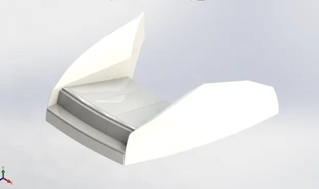
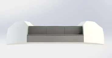
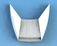
Front seat
Description: Front seat used to make chilling for passengers and designed for aesthetics
purpose
Tools used
- Line
- 3D sketch
- Rectangle
- Spline
- Circle
Constraints used
- Vertical
- Horizontal
- Coincident
- Perpendicular
- Pierce relation
Features used
- Swept surface
- Extrude surface
- Trim surface
- Loft extrude surface
- Knit surfaces
- Chamfer
- Mirror
- Cut extrude
- Dome
- Extrude boss/bass
- Fillet
Methodology
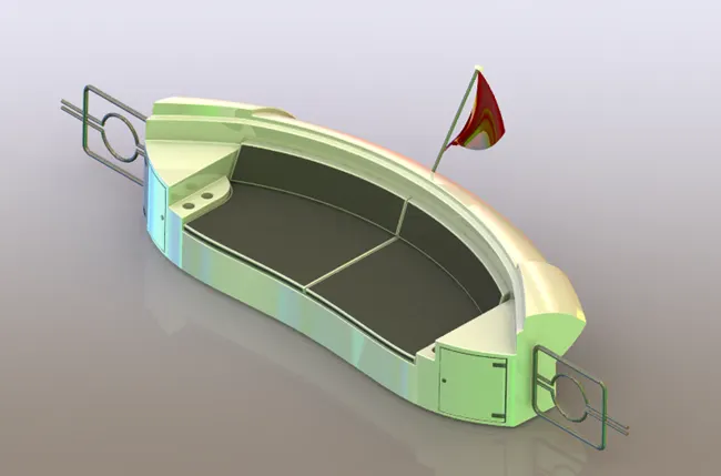
The front seat sketch is drawn using the surface from the hull for reference after making sketch in hull to extrude base part followed the sketches surface tools used to build a complete seat .Planes created vital roles for seat designs
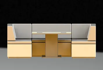
Middle seat
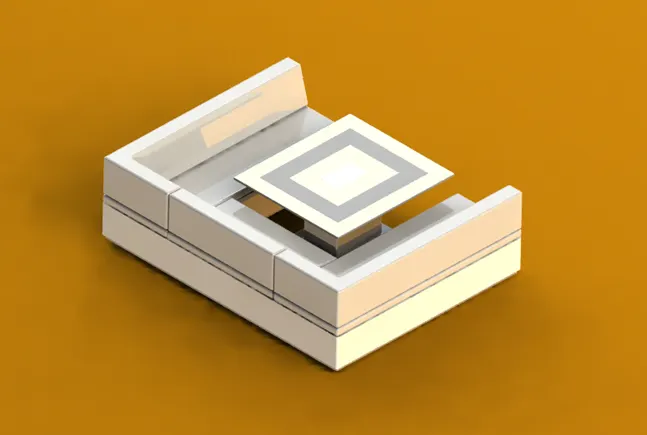
Description
“Middle seat is located at the end of the super structure used for taking rest and making fun of rider with the table’’
Tools used
- Line
- 3D sketch
- Rectangle
- Spline
- Circle
Constraints used
- Vertical
- Horizontal
- Coincident
- Perpendicular
- Pierce relation
Features used
- Swept surface
- Extrude surface
- Trim surface
- Loft extrude surface
- Knit surfaces
- Chamfer
- Mirror
- Cut extrude
- Extrude boss/bass
- Fillet
Methodology
The methodology of making is same as front seat surface reference of hull making extrude and using chamfers for seats it additionally contains table design achieved as per geometry .

Rear seat
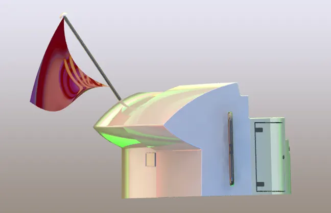
Description
Rear seat which is located at end of the deck it has a flag in rear side
Tools used
- Line
- 3D sketch
- Rectangle
- Spline
- Circle
Constraints used
- Vertical
- Horizontal
- Coincident
- Perpendicular
- Pierce relation
Features used
- Swept surface
- Extrude surface
- Trim surface
- Loft extrude surface
- Knit surfaces
- Chamfer
- Mirror
- Cut extrude
- Extrude boss/bass
- Fillet
- Offset surface
- Combine
- Ruled surface
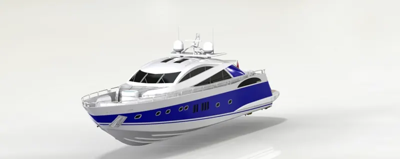
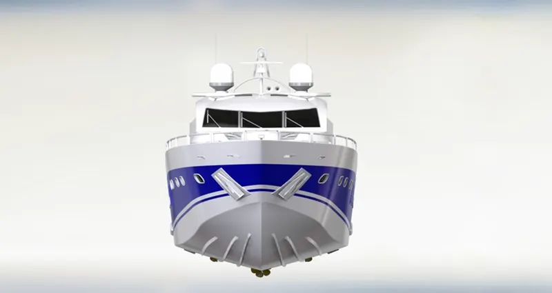
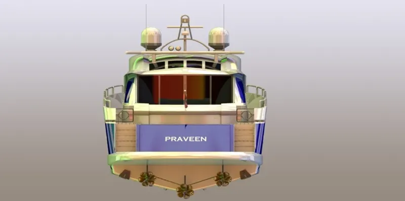
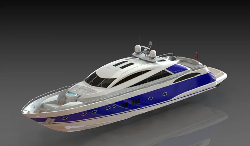
ASSEMBLY AND RENDEERING OF YACHT
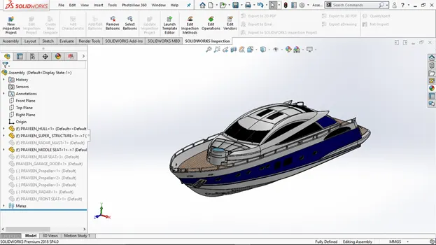
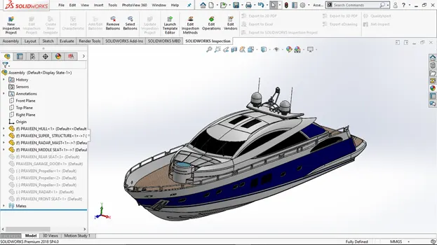
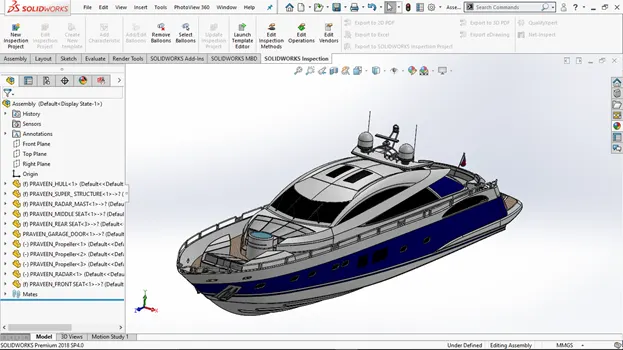
After finishing part and surface modeling of yacht the models undergoes to assembly to make a complete yacht
VIEWS OF YATCHT
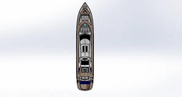
TOP VIEW
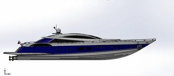
SIDE VIEW
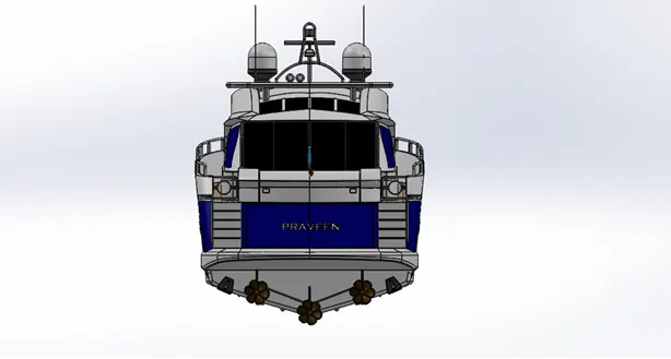
BACK VIEW
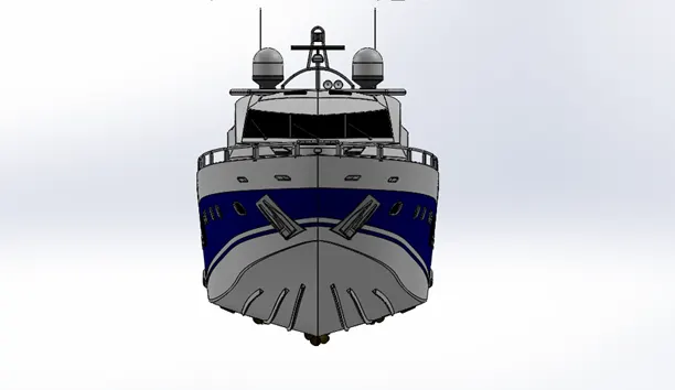
FRONT VIEW
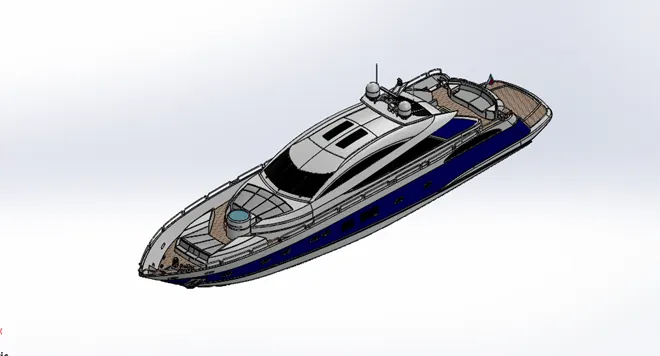
ISOMETRIC VIEW
RENDERING
Appearance , Environments, Lights, Camera
The rendering in solid works using photo view 360 and Solid works Visualize
Steps of rendering
- Apply appropriate appearance for parts appearance apply based on face , body
- Making proper environment
- Fix the lights where ever needed
- Fix the camera positions for rendering
FINAL RENDERS
CONCLUSION
In end of this project learn to use a new features and tools hands on experience of advanced surfacing and surface tools and learn about assembly according to planes of models including advanced mates Finally learning about Light, environment setup , colour , Decals , Back plates
Using Photo view 360 and solid works Visualize