Section Modulus calculation and optimization
SECTION MODULUS:
INTRODUCTION:
Section modulus is a geometric property for the given cut section of the profile.
By doing calculation of this section modulus, we can find out the capacity of the cut section will suitable for developing the product or not.
This modulus includes the geometric properties like area for tension and shear, radius of gyration for compression & moment of inertia and polar moment of inertia for stiffness.
This is the important calculation need to do in the BIW components to know about the strength.
It will calculate by using the formula of S=I/Y where S= Section Modulus, I = moment of inertia & Y = distance to the top from the neutral axis.
There are two types of section modulus,
- Elastic section modulus.
- Plastic section modulus.
ELASTIC SECTION MODULUS:
For all general design we need to use this elastic section modulus depends upon the profiles like square, rectangle, circle, beams, etc.
It will be applied up to the yield point of the component.
PLASTIC SECTION MODULUS:
This modulus is used in the location where the elastic yielding is up to the acceptable limit and to maintain below the plastic limit to avoid permanent deformation.
OBJECTIVE:
Need to find out the section modulus of the designed hood assy., to check the strength and load capacity.
CASE-1:
From the available hood design, we need to take the cut sketch section.
By using that cut sketch we need to create modify it to the closed loop sketch by keeping the outer line.
We need to measure the section inertia by using that closed loop sketch.

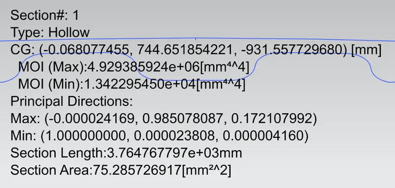
By using original design, we got the value of
MOI (Max) (I Max) = 4.93 e+06 mm4
MOI (MIN) (I Min) = 1.34 e+04 mm4
Section Length = 3.76 e+03 mm
Section Area = 75.28 mm2
Cut Section total length = 879.114 mm
Y = Cut section total length/2 = 879.114/2 = 439.557 mm
S= I Max/Y = 4930000/439.557 = 11215.838 mm3
S= I Min/Y = 13400/439.557 = 30.48 mm3
CASE-2:
From the original design we need to do offset inward of 0.5 mm.

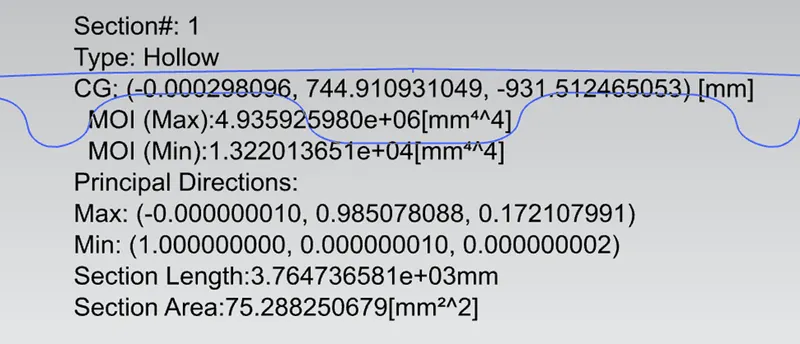
By using that, we got the value of
MOI (Max) (I Max) = 4.94 e+06 mm4
MOI (MIN) (I Min) = 1.32 e+04 mm4
Section Length = 3.76 e+03 mm
Section Area = 75.28 mm2
Cut Section total length = 879.114 mm
Y = Cut section total length/2 = 879.114/2 = 439.557 mm
S= I Max/Y = 4940000/439.557 = 11238.587 mm3
S= I Min/Y = 13200/439.557 = 30.03 mm3
CASE-3:
From the original design we need to do offset outward of 0.5 mm.

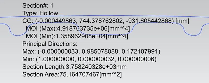
By using that, we got the value of
MOI (Max) (I Max) = 4.92 e+06 mm4
MOI (MIN) (I Min) = 1.36 e+04 mm4
Section Length = 3.76 e+03 mm
Section Area = 75.16 mm2
Cut Section total length = 879.114 mm
Y = Cut section total length/2 = 879.114/2 = 439.557 mm
S= I Max/Y = 4920000/439.557 = 11193.09 mm3
S= I Min/Y = 13600/439.557 = 30.94 mm3
CONCLUSION:
When compare to trail of Case 2 & Case 3 with original cut section sketch, Case 2 condition applied found ok.
Due to this result, by reducing the gap of outer panel and inner panel the stiffness, flexibility, strength, mass is improved.