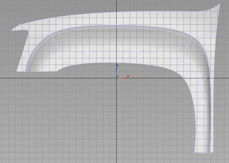
Challenge 6 : Concept Modeling of Side Fender
|
CONCEPT MODELING OF SIDE FENDER |
|
OBJECTIVE: |
|
To know about surfacing by using line drawing traced by using side, front and back view images. |
|
INTRODUCTION: |
|
Need to create the surface by using week 6 image tracing line drawing and to develop also. |
|
DESIGN METHODOLOGY / APPROACH: |
|
1. We need to place the image inside the grid box. |
|
2. We need to create a dimension box and place the image inside the box as per dimension available in blue print. |
|
3. By using CV, line, ellipse, circle, blend this we need to trace the image & need to create the line drawing. |
|
4. Once tracing completed, we need to start to creating surface by using skin, rail & square option. |
|
5. Using of layer, we need to assign the surface , sketch and box separately. |
|
6. Using of symmetric option opposite side also surface will create automatically by assigning the surface to layer. |
|
7. By visualization option we can apply themes to the surface to make aesthetic look, check how many surfaces are available and can able to find out the errors also. |
|
8. Using of G0, G1 & G2 option the surface to surface and line to line has been matched. |
|
9. Using trim option, the unwanted surface has been removed. |
|
10. Using project option, the sketch has been projected to the surface. |
|
11. Using of untrim we can undo the trim surface to its original. |
|
12. By using surface continuity tool we can cross verify that the line is continuous or not. |
|
13. By using duplicate option we can make rotation array by using surface. |
|
DESCRIPTION: |
|
1. By using skin command the surface has been created. |
|
2. By using square command the closed loop surface has been created. |
|
3. By using Rail command generation surface has been created. |
|
4. By using square surface command 90% of surface has been created. |
|
5. By using CV I created closed loop lines to create surface. |
|
6. By using trim command the unwanted surface will be removed. |
|
7. By using project option the sketch will be project to the required surface. |
|
8. By using multi colour option we cross verified that the surface is created or not. |
|
9. By using G0, G1 & G2 the surface and line has been matched. |
|
10. By using untrim option we can modify already trimmed surface. |
|
11. By using duplication we can make polar array the surface. |
|
CONCLUSION: |
|
Herewith I learned how to create line drawing from traced image and by using line drawing how to create surface, how to project and how to trim the unwanted surface. . |
FRONT BONNET:
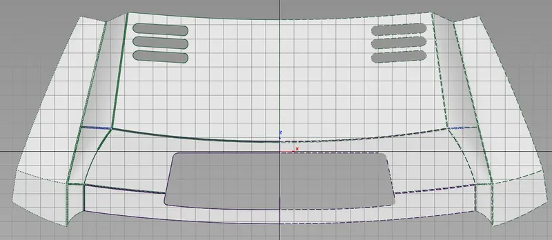
SIDE FENDER: