Section Modulus calculation and optimization
Section Modules:
What is Section Modules:
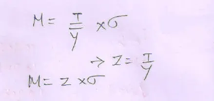
Section modules is the ratio of area moment of ineratia about natural axis and to the distance of outer most fiber from the netural axis.
Z = I/Y (Unit = mm3 or m3 )
Z = Section Modulus
I = Moment of Inertia
Y = distance from the neutral axis to the outer most fiber.
What is Natural Axis ?
Natural Axis is the cross section of beam or shaft and there is no longtudinal stress or strain.That is called natura axis.
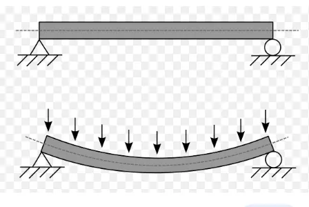
Area Moment of Inertia:
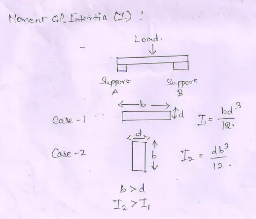
Is a Second moment of area or Second area moment or Quadritc moment of area is known as moment of inertia.is the property of two dimensional plane shape shows how the points are dispresed in an arbitatry axis in cross sectional plane that is called area moment of inertia.
They are two cases are there, That is,
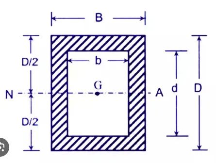
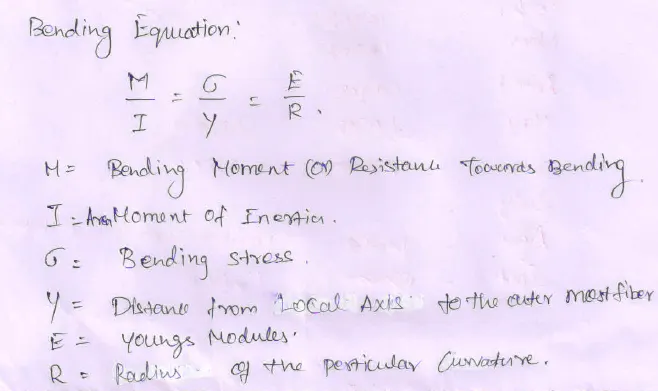
Bending Equation:
Section Modules Analysis:
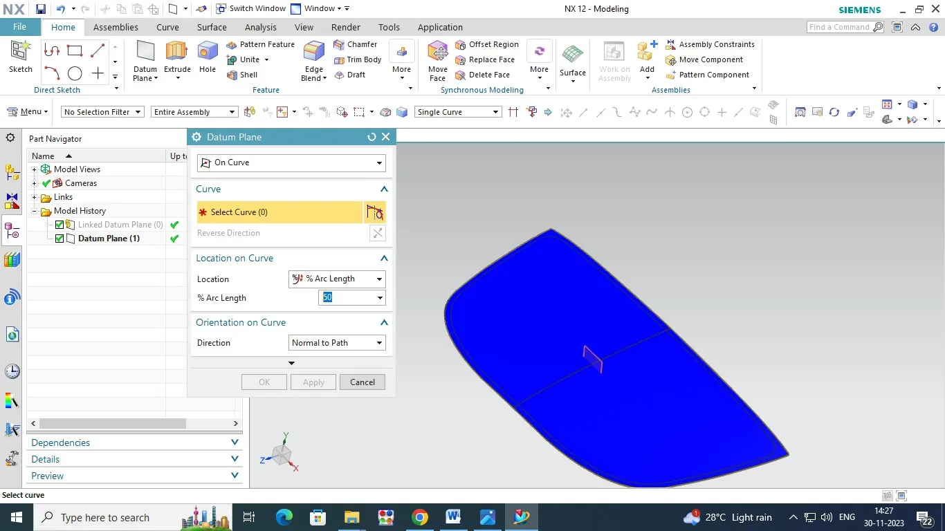
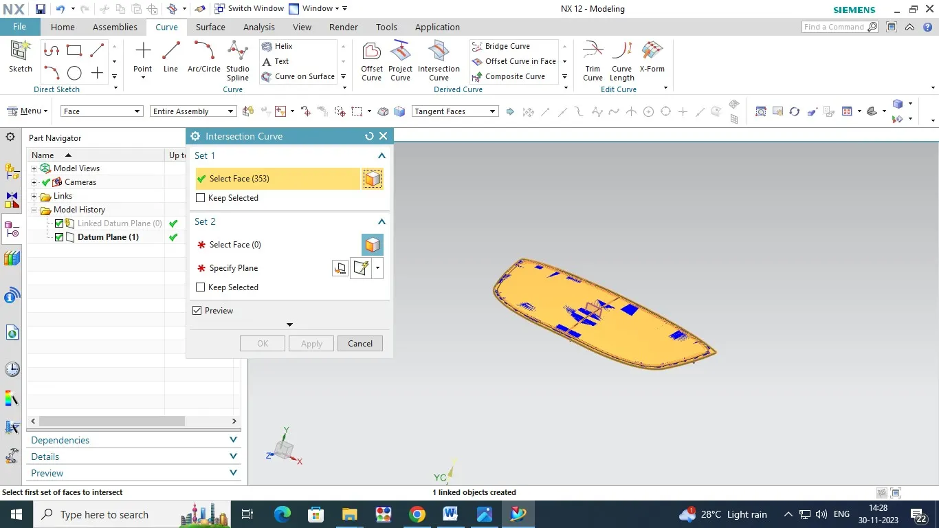
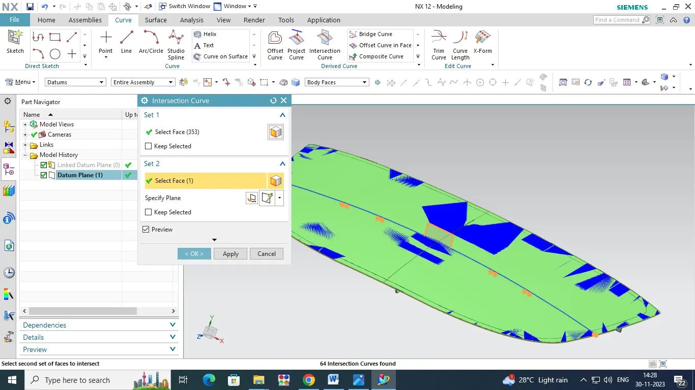
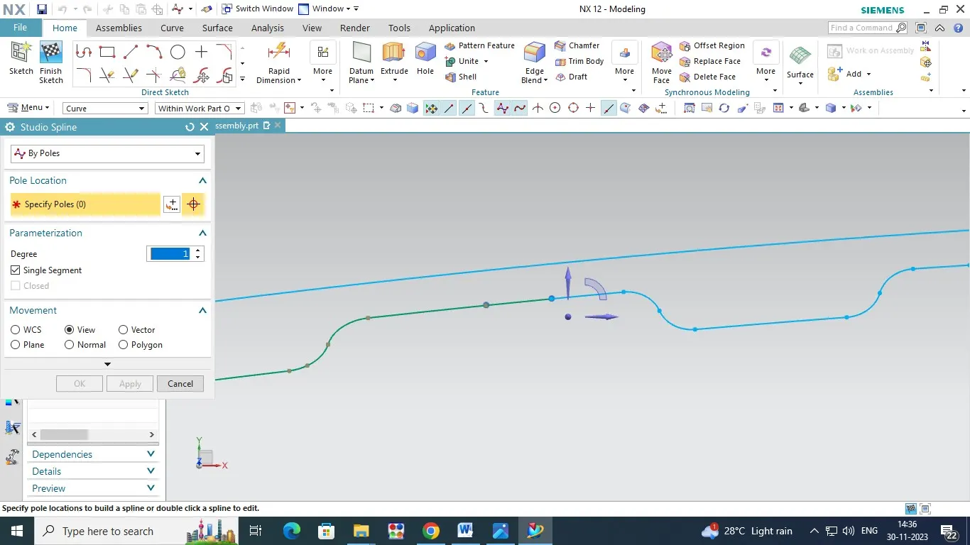
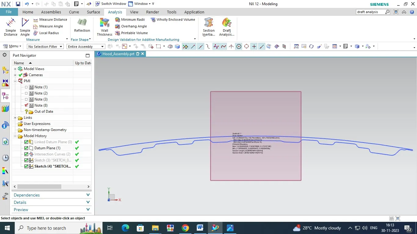
1. Open the Assembly File (Hood Assembly)and activated ,then the create the datum plane (YX Direction ) for center of axis in Hood.And we have to click on Intersection curve for creating the intersection line curve for the hood Assembly (Both Inner and outer Panel Also).
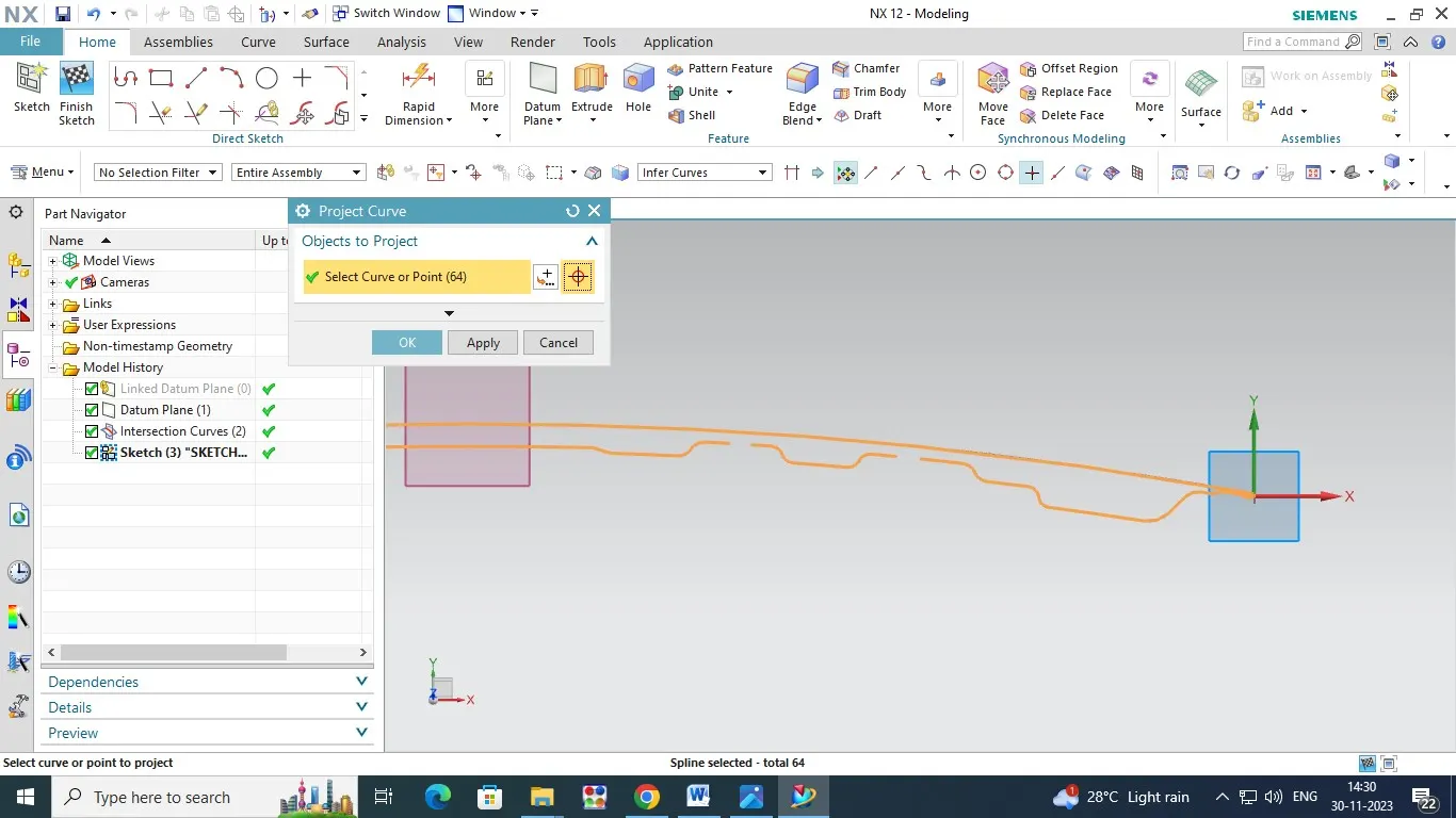
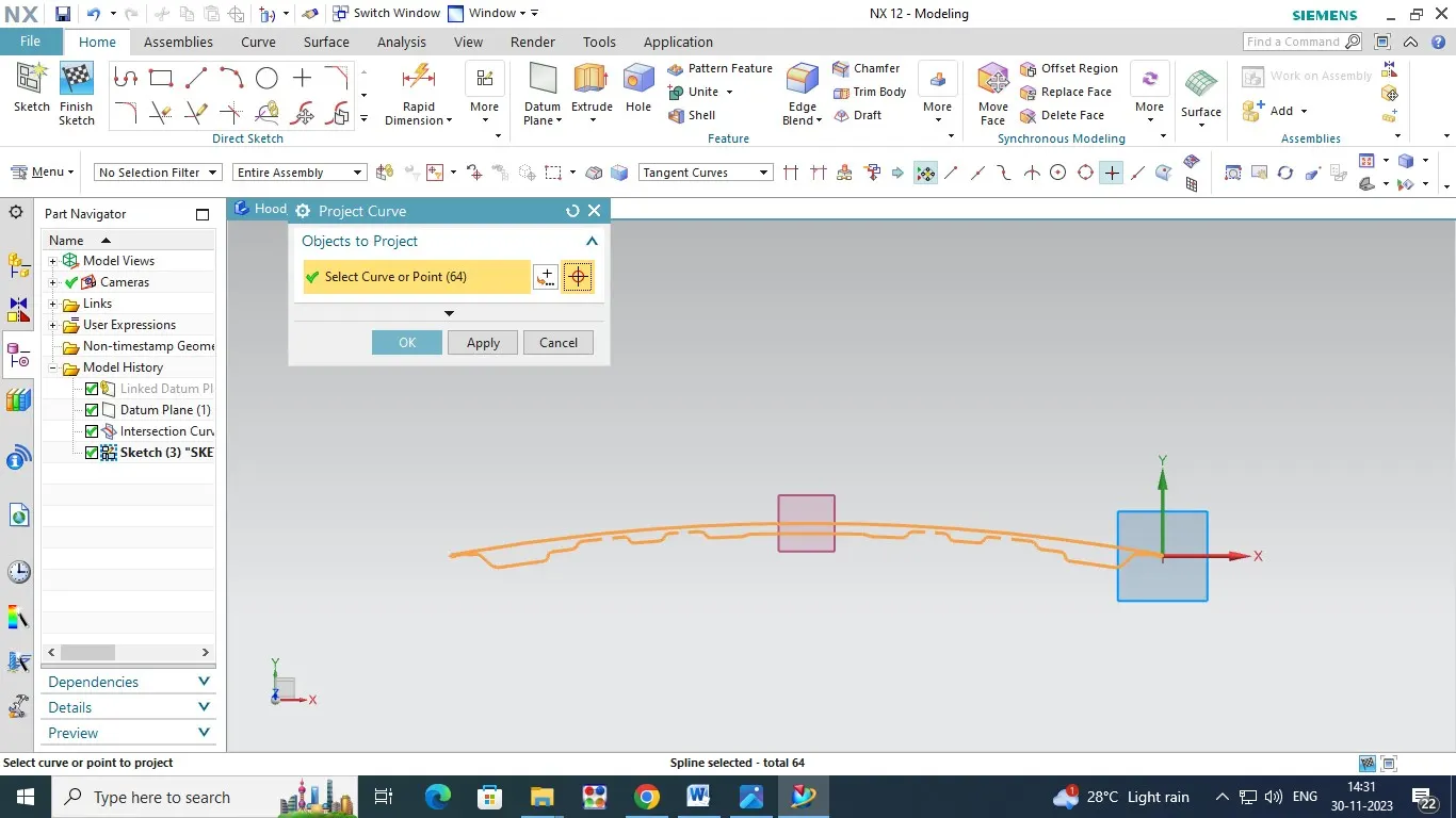
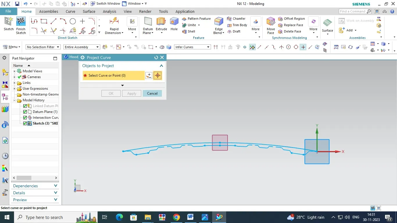
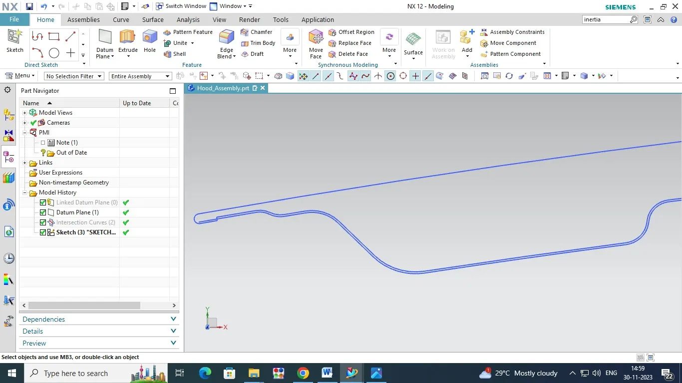
2. After the Intersection line we will convert the projection curve from intersection curve line and change the lines,connected the the irrugular line by using Spline command ,Trim the unwanted line for intersection lines.
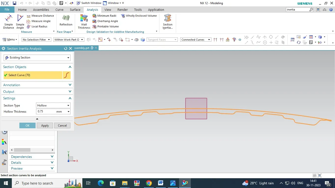
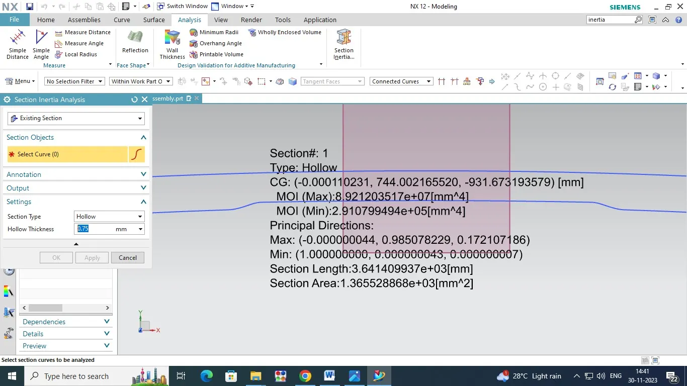
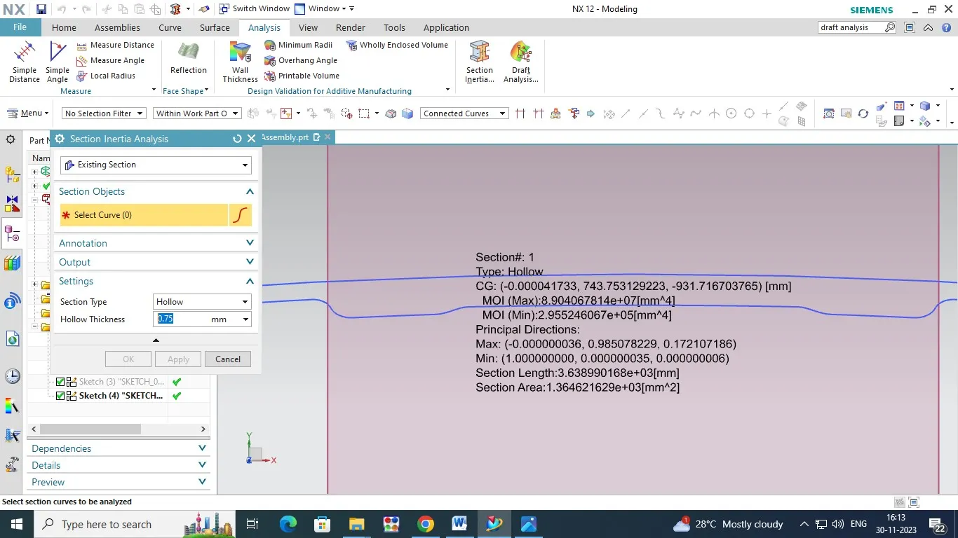
3. Finally we had to select the Section of inertia command ,open the window then change the option (excesting Section and Hood Thickness 0.75mm) and say ok.Then Show of Section modules of Moment of inertia (MOI) Maximum and Minimum , Principle Direction Maximum and Minimum Also.
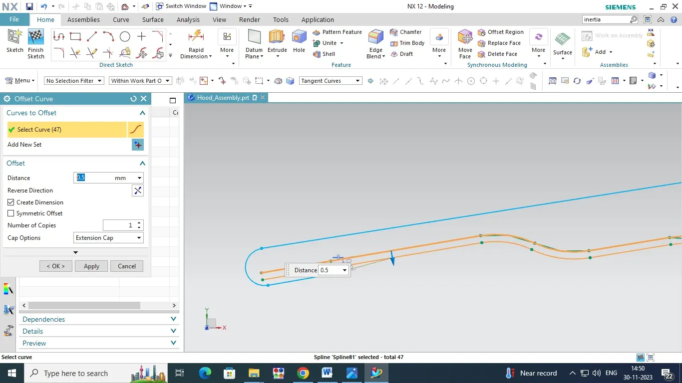
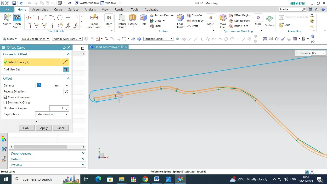
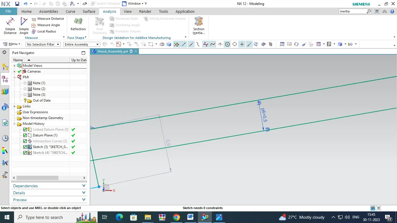
4. Now We have to change on incress distance or Gap from Outer Panel to Inner Panel is 0.5mm . Offset of the inner panel Intersection Curve line in 0.5mm ,and then we will convert the projection curve from intersection curve line and change the lines,connected the the irrugular line by using Spline command ,Trim the unwanted line for intersection curve lines.
5. Finally we had to select the Section of inertia command ,open the window then change the option (excesting Section and Hood Thickness 0.75mm) and say ok.Then Show of Section modules of Moment of inertia (MOI) Maximum and Minimum , Principle Direction Maximum and Minimum Also. This Result or some Different to the previous result.
INCRESS THE GAP FROM OUTER PANEL TO INNER PANEL : 0.5MM
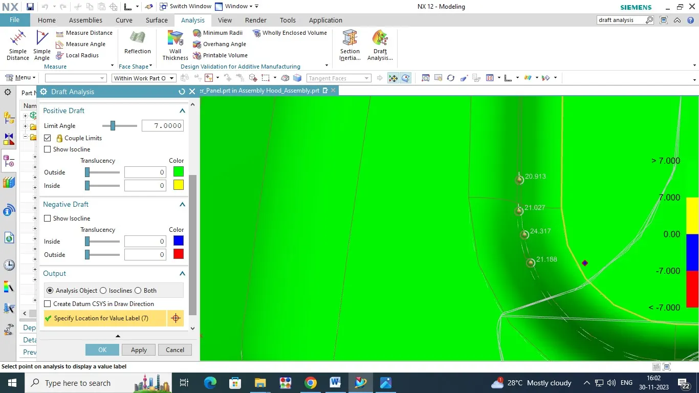
Draft Analysis for Hood Inner Panel :
1. Draft Analysis is most important thing for automotive product desigining,because this method only revil for correct angle of produt dimensions and design constructions.
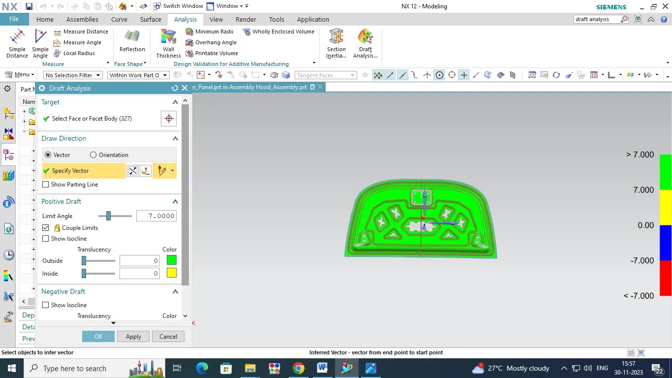
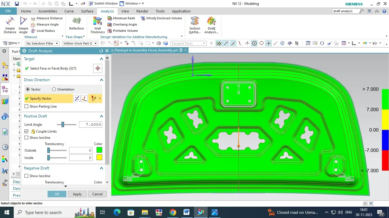
2.Select and consider the hood inner panel click on the draft analysis command open the window and select the face on inner pannel and select the vector .in this product design we have to consider the vector is tooling Axis direction.So select the tooling Axis.Now we have input the Tooling Axis angle value .Every product desiging the minimum tooling axis angle is Minimum 7 deg ,So Enter the 7 deg and say ok.
Some color verition are created in the inner panel product.They are ,
1. 0 to 7 Deg - Yellow color.
2. 7 to >7 Deg - Green Color.
3. 0 to -7 Deg - Blue Color.
4. -7 to < -7 Deg - Red Color.
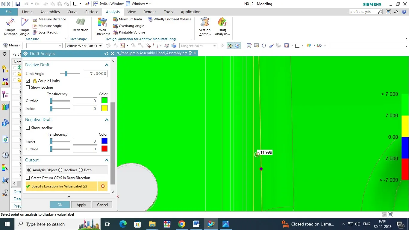
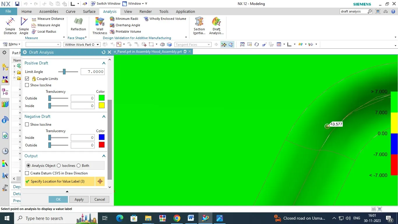
Now the inner Panel have Green Color.So we have identify the Draft angle for Minimum 7 Deg.