Section Modulus calculation and optimization
Title- calculation of section modulus of hood design and also come up with improved section modulus
Introduction
SECTION MODULUS
- Section modulus is the ratio of total moment resisted by the section to the stress in the extreme fibre.
- Section modulus give us idea about how much of load the given structure can take.
- If the section modulus increases the moment of resistance increases and hence its load bearing capacity.
- S=I/Y ,
Formula of section Modulus: It may be defined as the ratio of total moment resisted by the section to the stress in the extreme fibre which is equal to yield stress.
Which is equal to yield stress.
Therefore
S=I/y, Where
S= Section modulus (mm^3)
I = Moment of inertia of the section to the stress in the extreme end of the object (mm^4)
Y= Distance between the neutral axis and extreme end of the object (mm).
Area Moment of Inertia:
The area moment of inertia of a beam cross section area measures the beam ability to resist bending. The larger the moment of inertia less will be the bend.
Where,
M = Bending Moment
I = Area moment of Inertia
E = Young modulus
R = Radius of gyration
Neutral Axis: When beam is subjected to pure bending the top most fibres of the beam are subjected to maximum compression, while the bottom most fibre of the beams are subjected to maximum tension.
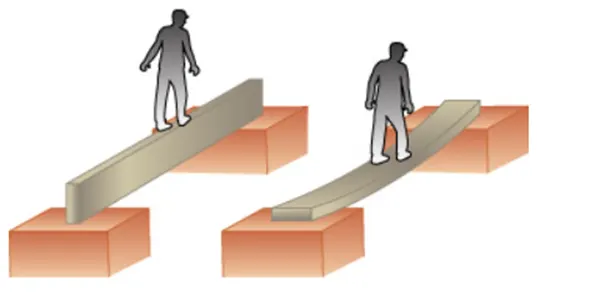
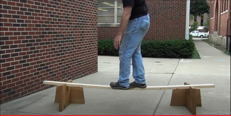
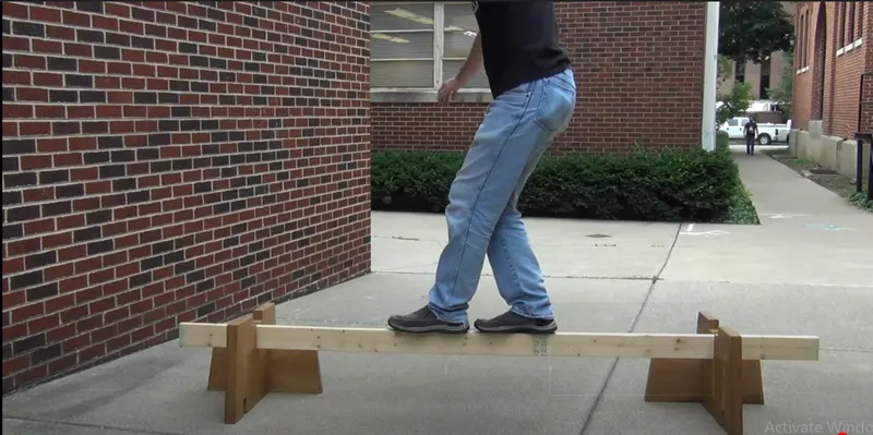
- This picture contains the following scene, Diagram of a beam on its narrow edge supported at both ends. A man is walking on a straight beam. Diagram of a beam resting on its flat side supported at both ends. A man is walking on the straight beam and its bending in the middle.
| Cross-sectional shape | Figure | Equation | Comment |
|---|---|---|---|
| Rectangle |  |
Solid arrow represents neutral axis | |
| doubly symmetric I-section (major axis) | 
|
NA indicates neutral axis | |
| doubly symmetric I-section (minor axis) |  [4] [4] |
NA indicates neutral axis | |
| Circle |  [3] [3] |
Solid arrow represents neutral axis | |
| Circular hollow section |  |
Solid arrow represents neutral axis | |
| Rectangular hollow section |  |
NA indicates neutral axis | |
| Diamond |  |
NA indicates neutral axis | |
| C-channel | |
NA indicates neutral axis |
 ,
,
HOW TO CALCULATE MOMENTOF INERTIA MATHEMATICALLY?
LET US UNDERSTAND MOI BY A GIVEN PROBLEM
calculate moi of given I section to understand how to find moi
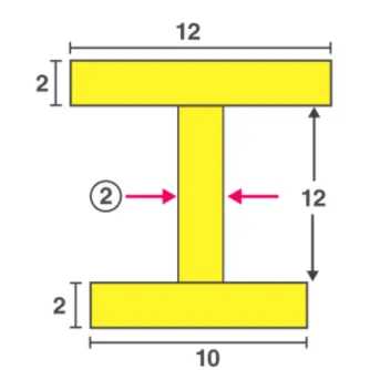 c
c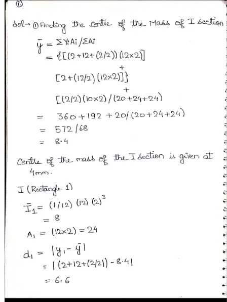
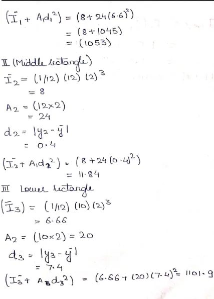
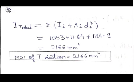
Question-using the section from previous hood design calculate the section modulus and also come up with a new section that has improved the section modulus of the previous section and mention what changes made that increased the length?
Sol-
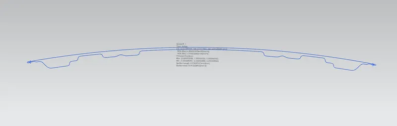
CASE 1
Hood design
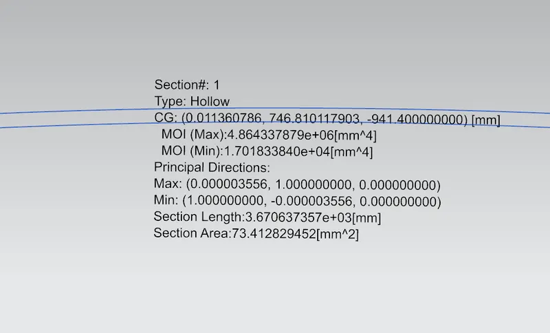
Moment of inertia (max)=4.864337879`*10^4mm^4
Moment of inertia(min)=1.88739⋅104mm4">1.701833840mm41.88739⋅104��4
value of y=440mm
section modulus=moi (min)/y
1.88739⋅104">1.88739⋅1041.88739⋅104/ 440
=38.67mm^3
CASE 2
hood optimised design
by adding +0.6 mm in the depth of hood
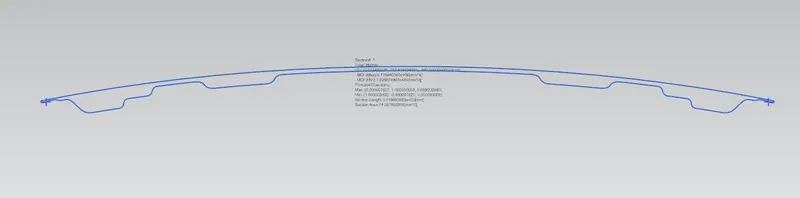
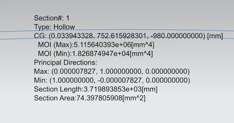
MOI (max) = 5.11560393`*10^4 mm^4
MOI (MIN)= 1.826874947*10^4 mm^4
s=66.89 mm^3
comparing case 1 and 2
percentage increase in optimised one= (66.89-42.89)/42.89
=5.5%
CONCLUSION
- By comparing the values we can clearly say that the section modulus of the optimized hood increases by 5.5%
- moment of inertia increases by increasing depth of hood.
- it seems if we increase the gap between inner and outer panel moi also increases.