Section Modulus calculation and optimization
OPTIMIZATION
AIM :
To calculate the Section modulus for the given hood model for two iterations and analyze which will the better to be considered.
SECTION MODULUS :
Section Modulus is also referred to as the Polar Modulus or the Torsional Sectional Modulus. It is denoted by Zp.
Section Modulus is the geometric property of the given cross-section of any shaft or beam structures. It is the direct measure of the strength of the shaft section or the beam section. Higher the section modulus of a structure, the more the resistive it becomes to bending.
The second moment of area is also known as the moment of inertia of a shape. It is directly related to the area of material in the cross-section and the displacement of that area from the centroid. Once the centroid is located, the more important structural properties of the shape can be calculated. The axis that determines the centroid is also known as the neutral axis (N/A).
The second moment of area is a measure of the 'efficiency' of a shape to resist bending caused by loading. A beam tends to change its shape when loaded. The second moment of area is a measure of a shape's resistance to change.
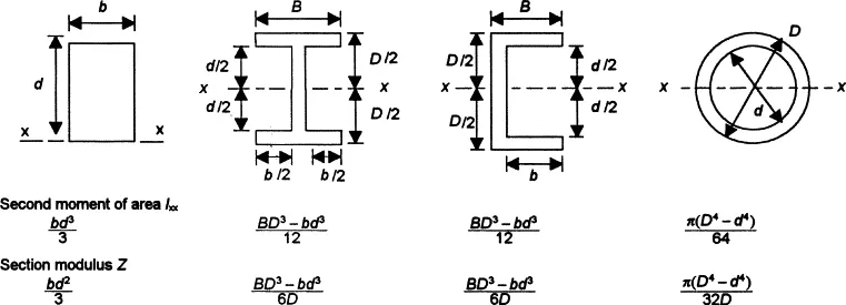
Use the formula: where b = breadth (width) and d = depth (height) to calculate the moment of inertia about the x-x axis for beams A and B using information from the diagram.
Section modulus is defined as the ratio of polar moment of inertia to the radius of the shaft or the distance from the neutral axis to the outer fibres.
For a beam which has been bent, the maximum stress σmax will occur at the maximum distance ymax from the neutral axis.
Thus:
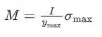
The quantity I/ymax is a purely geometric function and is termed the section modulus Z. Thus we can write:
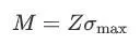
Therefore :
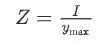
Z = Section modulus.
I = Moment of Inertia.
Ymax = distance between the neutral axis and the extreme end of the object.
PROCEDURE :
So here we are going to calculate the section modulus for the Hood Assembly upto two iterations and can analyze one with more section modulus.
Here we take the section of Hood assembly
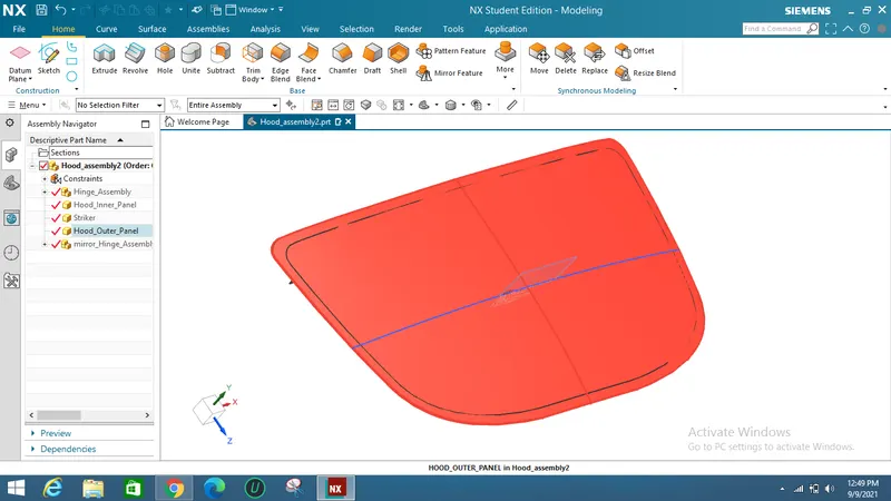
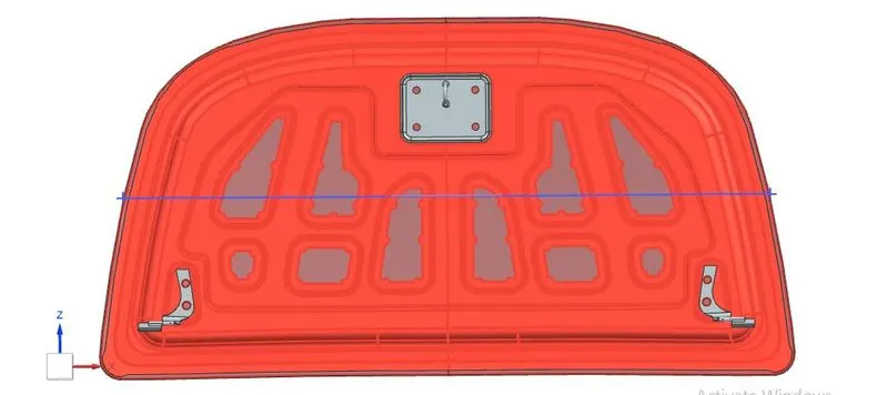
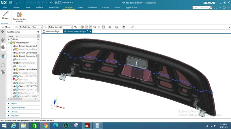
Now we take the intersection curve of the Outer and Inner hood and make a complete single closed curve for the inertia analysis.
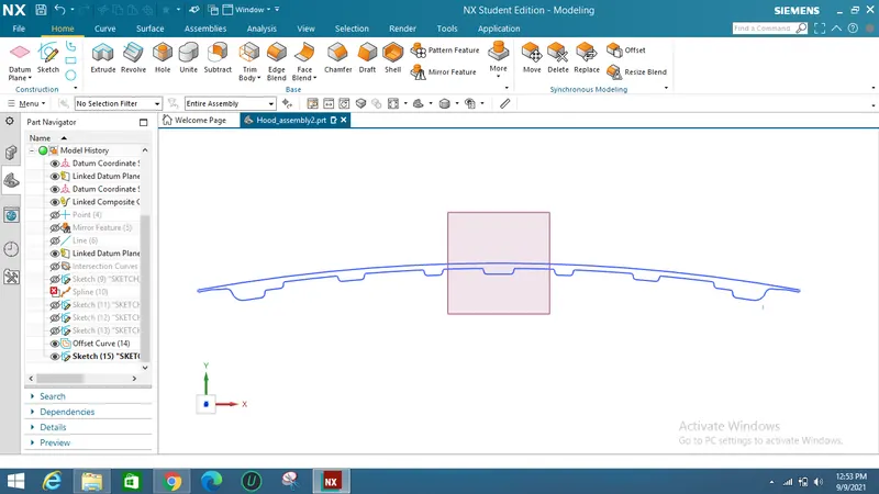
So now to find out the section interia we use a command called Section Inertia Analysis in the Analysis Tab.
1st ITERATION :
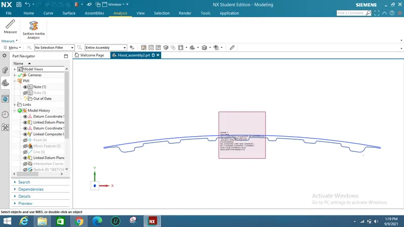
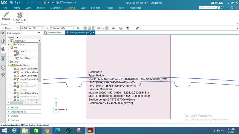
From the above Sectional Analysis the results apperared :
Moment of Inertia (Imin) = 1.457584724×104 mm^4
Moment of Inertia (Imax) = 4.877748399×106 mm^4
The Distance from neutral fibre to extreme fibre is calculated by making two points to the extreme of section and measuring distance between them and half it.
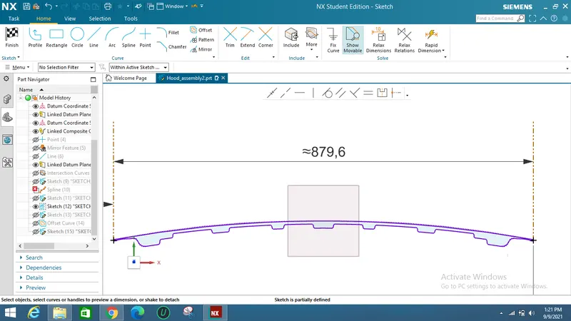
So the distance from neutral fibre is :(Ymax)
Ymax = 879.6/2 mm
Ymax = 439.8 mm
Section modulus :
Z(min) = (1/439.8)*1.457584724×104 mm^4
Z(min) = 0.003314188×104 mm^4
Z(max) = (1/439.8)*4.877748399×106 mm^4
Z(max) = 0.0110908×106 mm^4
2nd ITERATION :
In 2nd Iteration the inner hood panel is offset to 1mm outside so that the section area will be increased as Sectional Inertia is directly proportional to the sectional modulus the value of sectional modulus will increase.
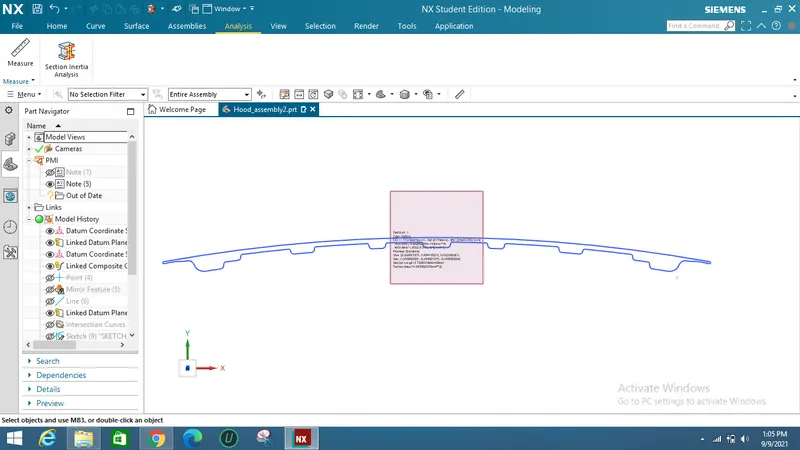
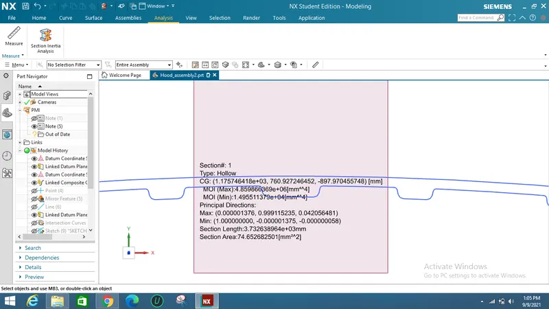
From the above Sectional Analysis the results apperared :
Moment of Inertia (Imin) = 1.495511379×104 mm^4
Moment of Inertia (Imax) = 4.859866369×106 mm^4
The Distance from neutral fibre to extreme fibre is calculated by making two points to the extreme of section and measuring distance between them and half it.
So the distance from neutral fibre is :(Ymax)
Ymax= 879.6/2 mm
Ymax= 439.8 mm
Section modulus :
Z(min) = (1/439.8)*1.495511379×104 mm^4
Z(min) = 0.003400435×104 mm^4
Z(max) = (1/439.8)*4.859866369×106 mm^4
Z(max) = 0.011050×106 mm^4
CONCLUSION :
Therefore the value of section modulus is increased from 0.003314188×104 mm^4 to 0.003400435×104 mm^4 with 1mm offset of the inner panel to outside. By the result of this we can say that increase in the cross sectional area of the section, the minimum load taking capacity of the part will be increased.