Section Modulus calculation and optimization
Title of the project:
To Analyse the section modulus of the hood and perform design optimisation on hood using NX CAD 12.
Section modulus:
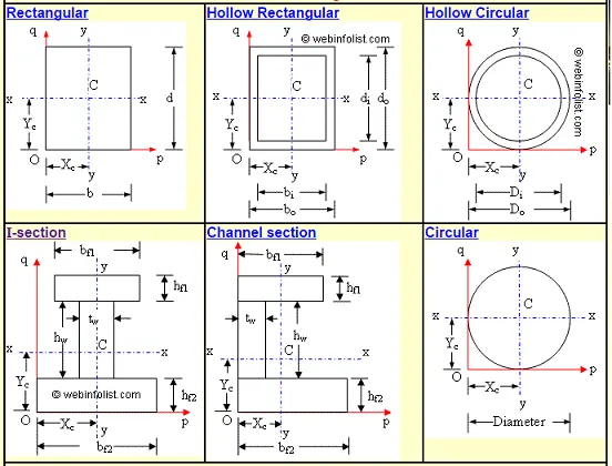
Section modulus is a geometric property for a given cross-section used in the design of beams or flexural members. Other geometric properties used in design include area for tension and shear, radius of gyration for compression, and second moment of area and polar second moment of area for stiffness. Any relationship between these properties is highly dependent on the shape in question. Equations for the section moduli of common shapes are given below. There are two types of section moduli, the elastic section modulus and the plastic section modulus. The section moduli of different profiles can also be found as numerical values for common profiles in tables listing properties of such.

Elastic section modulus
The elastic section modulus is defined as S = I / y, where I is the second moment of area (or area moment of inertia, not to be confused with moment of inertia) and y is the distance from the neutral axis to any given fibre. It is often reported using y = c, where c is the distance from the neutral axis to the most extreme fibre, as seen in the table below. It is also often used to determine the yield moment (My) such that My = S ⋅ σy, where σy is the yield strength of the material.
Plastic section modulus
The plastic section modulus is used for materials where elastic yielding is acceptable and plastic behavior is assumed to be an acceptable limit. Designs generally strive to ultimately remain below the plastic limit to avoid permanent deformations, often comparing the plastic capacity against amplified forces or stresses.
The plastic section modulus depends on the location of the plastic neutral axis (PNA).The PNA is defined as the axis that splits the cross section such that the compression force from the area in compression equals the tension force from the area in tension. So, for sections with constant, and equal compressive and tensile yielding stress, the area above and below the PNA will be equal, but for composite sections, this is not necessarily the case.
The plastic section modulus is the sum of the areas of the cross section on each side of the PNA (which may or may not be equal) multiplied by the distance from the local centroids of the two areas to the PNA:

The Plastic Section Modulus is not the 'First moment of area'. Both relate to the calculation of the centroid, but Plastic Section Modulus is the Sum of all areas on both sides of PNA (Plastic Neutral Axis) and multiplied with the distances from the centroid of the corresponding areas to the centroid of the cross section, while the First moment of area is calculated based on either side of the "considering point" of the cross section and it is different along the cross section and depends on the point of consideration.
The plastic section modulus is used to calculate the plastic moment, Mp, or full capacity of a cross-section. The two terms are related by the yield strength of the material in question, Fy, by Mp = Fy ⋅ Z. Plastic section modulus and elastic section modulus are related by a shape factor which can be denoted by k, used for an indication of capacity beyond elastic limit of material. This could be shown mathematically with the formula :-

Use in structural engineering
Though generally section modulus is calculated for the extreme tensile or compressive fibres in a bending beam, often compression is the most critical case due to onset of flexural torsional (F/T) buckling. Generally (except for brittle materials like concrete) tensile extreme fibres have a higher allowable stress or capacity than compressive fibres.
In the case of T-sections if there are tensile fibres at the bottom of the T they may still be more critical than the compressive fibres at the top due to a generally much larger distance from the neutral axis so despite having a higher allowable stress the elastic section modulus is also lower. In this case F/T buckling must still be assessed as the beam length and restraints may result in reduced compressive member bending allowable stress or capacity.
There may also be a number of different critical cases that require consideration, such as there being different values for orthogonal and principal axes and in the case of unequal angle sections in the principal axes there is a section modulus for each corner.
For a conservative (safe) design, civil structural engineers are often concerned with the combination of the highest load (tensile or compressive) and lowest elastic section modulus for a given section station along a beam, although if the loading is well understood one can take advantage of different section modulus for tension and compression to get more out of the design. For aeronautical and space applications where designs must be much less conservative for weight saving, structural testing is often required to ensure safety as reliance on structural analysis alone is more difficult (and expensive) to justify.
Moment of inertia
The moment of inertia, otherwise known as the mass moment of inertia, angular mass, second moment of mass, or most accurately, rotational inertia, of a rigid body is a quantity that determines the torque needed for a desired angular acceleration about a rotational axis, akin to how mass determines the force needed for a desired acceleration. It depends on the body's mass distribution and the axis chosen, with larger moments requiring more torque to change the body's rate of rotation.
It is an extensive (additive) property: for a point mass the moment of inertia is simply the mass times the square of the perpendicular distance to the axis of rotation. The moment of inertia of a rigid composite system is the sum of the moments of inertia of its component subsystems (all taken about the same axis). Its simplest definition is the second moment of mass with respect to distance from an axis.
For bodies constrained to rotate in a plane, only their moment of inertia about an axis perpendicular to the plane, a scalar value, matters. For bodies free to rotate in three dimensions, their moments can be described by a symmetric 3 × 3 matrix, with a set of mutually perpendicular principal axes for which this matrix is diagonal and torques around the axes act independently of each other
Importance of Section modulus:
- Increase in value of section modulus, leads to decrease in bending of component.
- Section modulus is a valuable factor for both beam and flexural designs.
- It helps in analysing the stresses in component and measure its strength as well.
- Any beam which has larger section
Methodology:
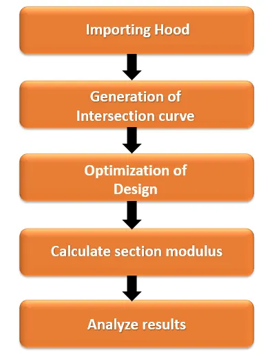
Steps followed in design Process:
- Importing of hood model to the workbench.
- Selecting the midplane of hood and generating the intersection curve.
- Measuring the section modulus of base model intersection curve.
- Modifying the sketch by offsetting the inner panel and measuring the section modulus.
- Modifying the sketch by reducing embosses the inner panel and measuring the section modulus.
- Modifying both reduced embosses and offsetting the inner panel and measuring the section modulus.
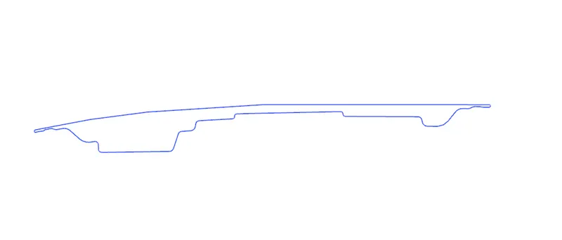
Baseline Hood model:
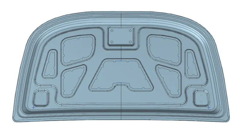
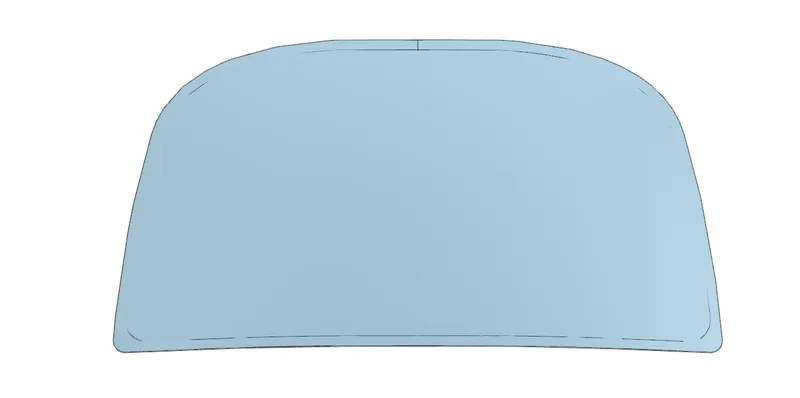
Intersection curve
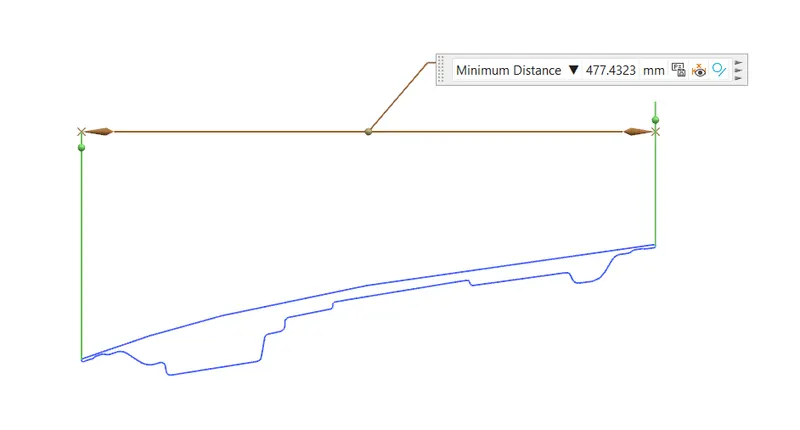
Neutral axis Distance
Optimization of Design:
- Case 1: The section modulus of baseline hood model is measured without any changes.
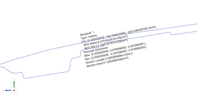
MOI (max) = 8.270164261 x 105 mm4
MOI (min) = 5.700124 ×10³ mm⁴
Y=477.4323/2 = 238.716 mm
S=I/Y mm³
S = 5.700124 ×10³ / 238.716
S = 23.878 mm3
- Case 2: In this case, the hood inner panel is offsetted to 0.5 mm towards outward side in the baseline model, as the design modification and section modulus is measured to analyse.
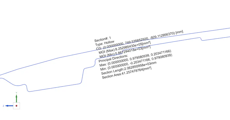
MOI (max) = 8.25299 x 105 mm4
MOI (min) = 5.88729 ×10³ mm⁴
Y=477.4323/2 = 238.716 mm
S=I/Y mm³
S = 5.88729 ×10³ / 238.716
S = 24.6623 mm3
9.Comparing of Results:
|
Cases |
MOI max in mm⁴ |
MOI min in mm⁴ |
Section Modulus |
|
Baseline model |
8.270164261 x 105 mm4 |
5.700124 ×10³ mm⁴ |
23.878 mm3 |
|
0.5mm Offseted |
8.25299 x 105 mm4 |
5.88729 ×10³ mm⁴ |
24.6623 mm3 |
Conclusion:
Based on the requirement the section modulus of the hood is carried out and performed design optimisation on the hood to improve the mechanical properties externally. Different cases of design optimization of hood is performed in order to attain maximum effective hood design .the results shows that case 4,that is reduced embosses with offsetted design modification provides maximum effective section modulus for the hood. The NX CAD helps to make the design accomplishment easier within time constraint