Section Modulus calculation and optimization
Aim:
To Calculate the Section Modulus of the Hood section.
There are two types of section moduli and they are
- Elastic section modulus
- Plastic section modulus.
Elastic section modulus
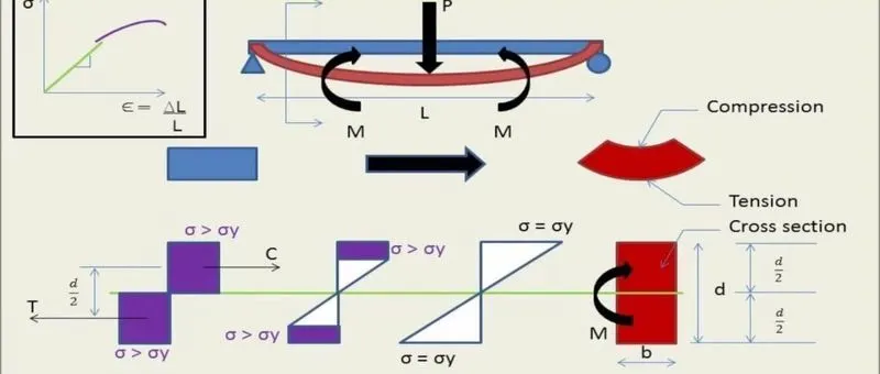
The elastic section modulus is defined as S = I / y, where I is the second moment of area (or area moment of inertia, not to be confused with moment of inertia) and y is the distance from the neutral axis to any given fibre. It is often reported using y = c, where c is the distance from the neutral axis to the most extreme fibre. It is also often used to determine the yield moment (My) such that My = S × σy, where σy is the yield strength of the material. For general design, the elastic section modulus is used, applying up to the yield point for most metals and other common materials.
Image of Elastic section modulus
Plastic section modulus
The plastic section modulus is used for materials where elastic yielding is acceptable and plastic behaviour is assumed to be an acceptable limit. Designs generally strive to ultimately remain below the plastic limit to avoid permanent deformations, often comparing the plastic capacity against amplified forces or stresses.
The plastic section modulus depends on the location of the plastic neutral axis (PNA). The PNA is defined as the axis that splits the cross section such that the compression force from the area in compression equals the tension force from the area in tension. So, for sections with constant yielding stress, the area above and below the PNA will be equal, but for composite sections, this is not necessarily the case.
The plastic section modulus is the sum of the areas of the cross section on each side of the PNA (which may or may not be equal) multiplied by the distance from the local centroids of the two areas to the PNA:
Zp=AcYc + AtYt
The plastic section modulus is used to calculate the plastic moment, Mp, or full capacity of a cross-section. The two terms are related by the yield strength of the material in question, Fy, by Mp=Fy*Z. Plastic section modulus and elastic section modulus are related by a shape factor which can be denoted by 'k', used for an indication of capacity beyond the elastic limit of material.
K= Z/S
Neutral Axis:
- The centermost layer of any section of a component is called the Neutral axis.
- Neutral Axis doesn't get affected by any kind of load that is perpendicular to it which means there is no stress or strain on the neutral axis.
- The range of stress varies with respect to the distance from the neutral axis.
SECTION MODULUS:
Section modulus is defined as the ratio of the moment of inertia of a section about the neutral axis to the distance of the outermost layer from the neutral axis. It is denoted by the symbol S. Hence mathematically section modulus is given by,
- S=I/Y-max
- where
- I=Moment of Inertia about the neutral axis and
- Y-max = Distance of the outermost layer from the neutral axis.
we know Max Bending Moment(M)/ moment of inertia(I) = Stress(σ)/strain(Y)
The stress σ will be maximum when y is maximum. Hence above equation can be written as
- M/ I = (σ-max)/(Y-max)
- M= σ max*(I/Y-max)
But
- I/(Y-max)=Z
- M = σ max * Z
In the above equation, M is the maximum bending moment (or moment of resistance offered by the section). Hence moment of resistance offered by the section is maximum when section modulus Z is maximum. Hence section modulus represents the strength of the section.
Note: Section Modulus varies with respect to the shape of the cross-section.
Factors that influence the section modulus:
- Area - Area is directly proportional to section modulus
- Thickness of sheet metal- Thickness is also directly proportional to the section modulus
- Distance between the outermost layer to the neutral axis called Y. Y is inversely proportional to section modulus.
- Cross-sectional depth of the component - It is directly proportional to the sectional modulus.
Section Modulus Analysis using UGNX:
Procedure for an increase in the area:
Case-1: Increasing the area by offsetting the outermost layer.
At Zero Offset:
- Select the Part body on which we have to do analysis and create a cross-section of the part and make sure that the cross-section sketch is a closed profile.
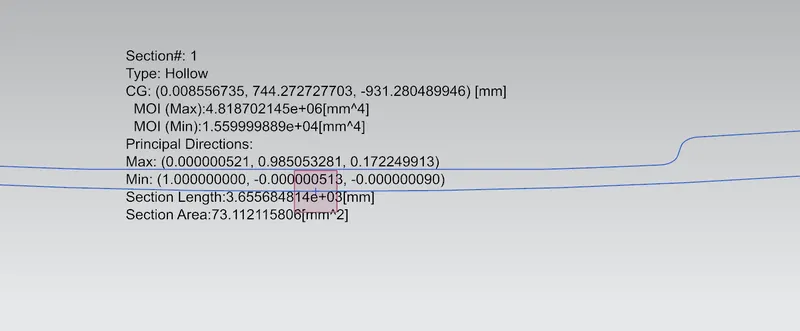
- Perform Section Inertia Analysis over the section that we have created and there we can find the result as shown below
- Create a CG point by using the point command and measure the distance between the point on the outermost layer and the CG point by using the measure command in analysis.
- Here the reason to take Y parallel to the x-axis is if we take the loading condition perpendicular to the x-axis then the Y value also increases as the Area increases but we have to keep one parameter constant for that we took the loading condition parallel to X-axis(this condition can be taken on a side impact).
- The Distance we got here is 879/2=439.5mm
- According to the formula For section modulus
-
S = I/Y
-
Where,
S = Section Modulus
I = Moment of Inertia
y = distance between the neutral axis and the extreme end of the object
- MOI min/Y = (1.559999889x10^4)/439.5 = 35.4948780205mm^3
- MOI max/Y = (4.818702145x10^6)/439.5 = 10964.0549374 mm^3
- Section Modulus at MOI min = 35.4948780205 mm^3
- Section Modulus at MOI max = 239726.396161 mm^3
At 0.5 mm Offset:
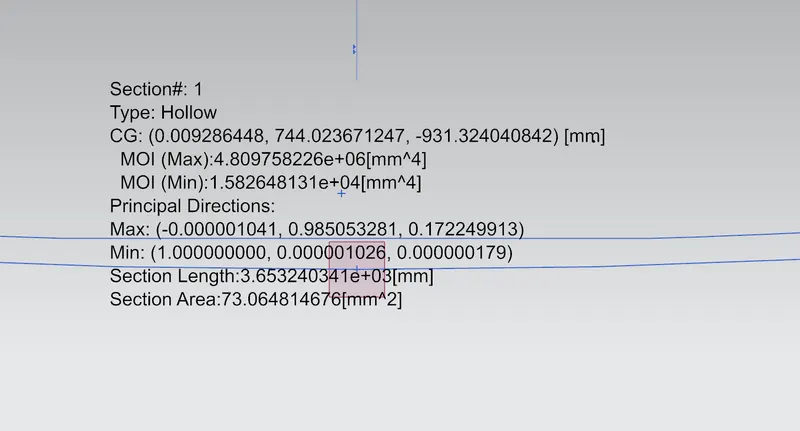
- MOI min/Y = (1.583204158x10^4)/439.5 = 36.0228477361 mm^3
- MOI max/Y = (4.891673592x10^6)/439.5 = 11130.0878089 mm^3
- Section Modulus at MOI min = 36.0228477361 mm^3
- Section Modulus at MOI max = 11130.0878089 mm^3
At 1 mm Offset:
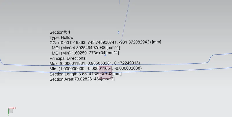
- MOI min/Y = (1.602591273x10^4)/439.5 = 36.463965256 mm^3
- MOI max/Y = (4.802549497x10^6)/439.5 = 10927.3026098mm^3
- Section Modulus at MOI min = 36.463965256 mm^3
- Section Modulus at MOI max = 10927.3026098 mm^3
Result:
From the above analysis we can say that the section modulus increases with an increase in offset value nothing but an increase in Cross-sectional area.