Roof Design
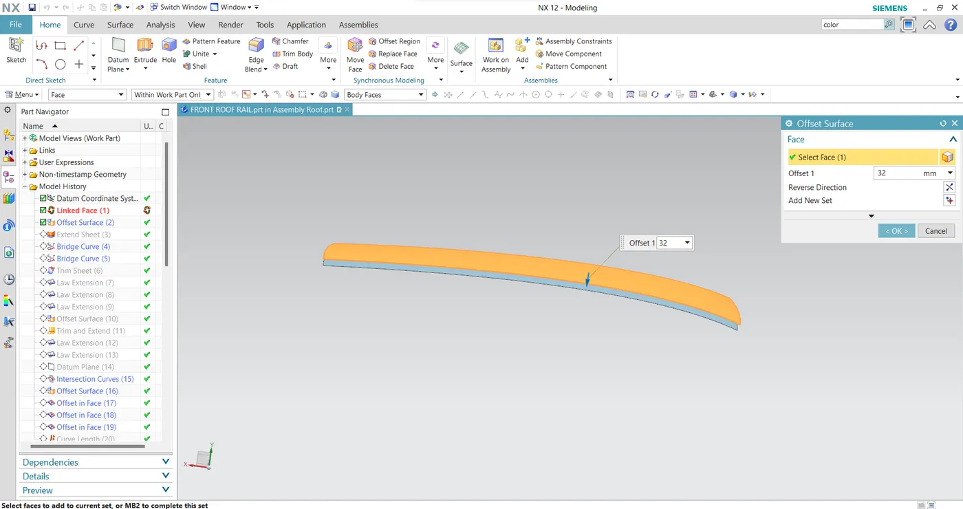
- linken the class A surface using wave geometry linker .
- offset the class A surface for 32 mm using offset surface.
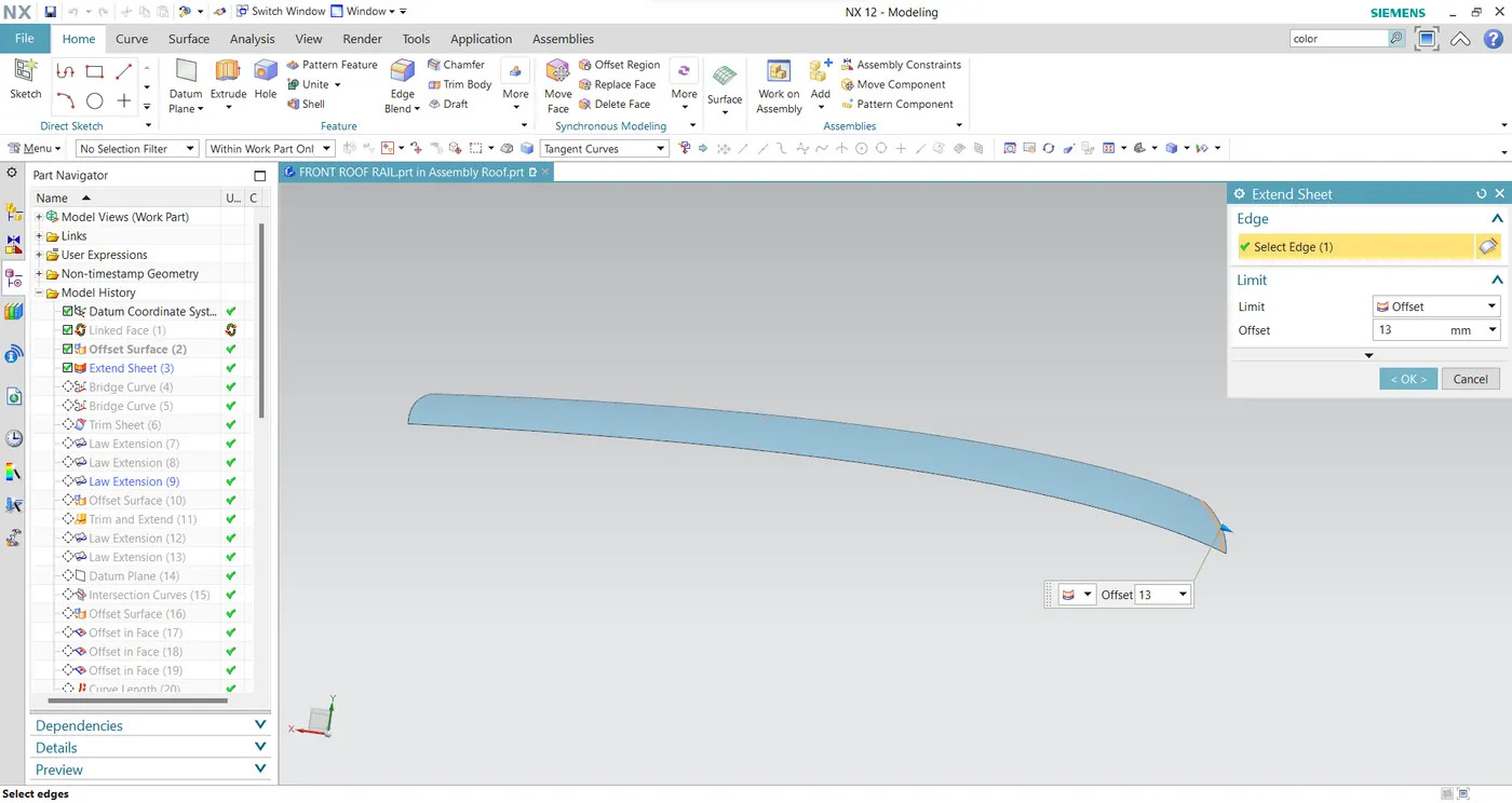
- extend the offset surface for 13mm using extend sheet.
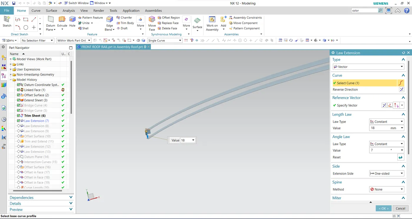
- law extend at the edges of the offset suface and class A surface by using law extension.
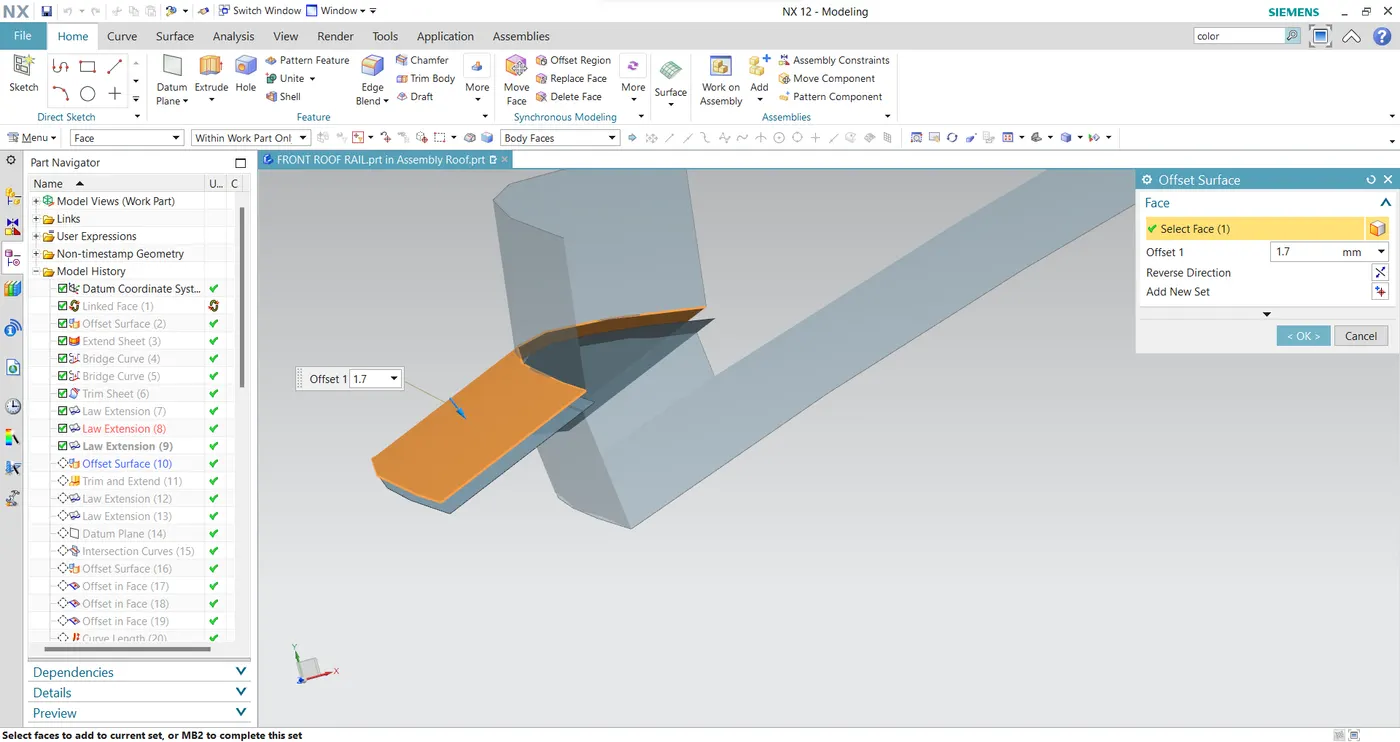
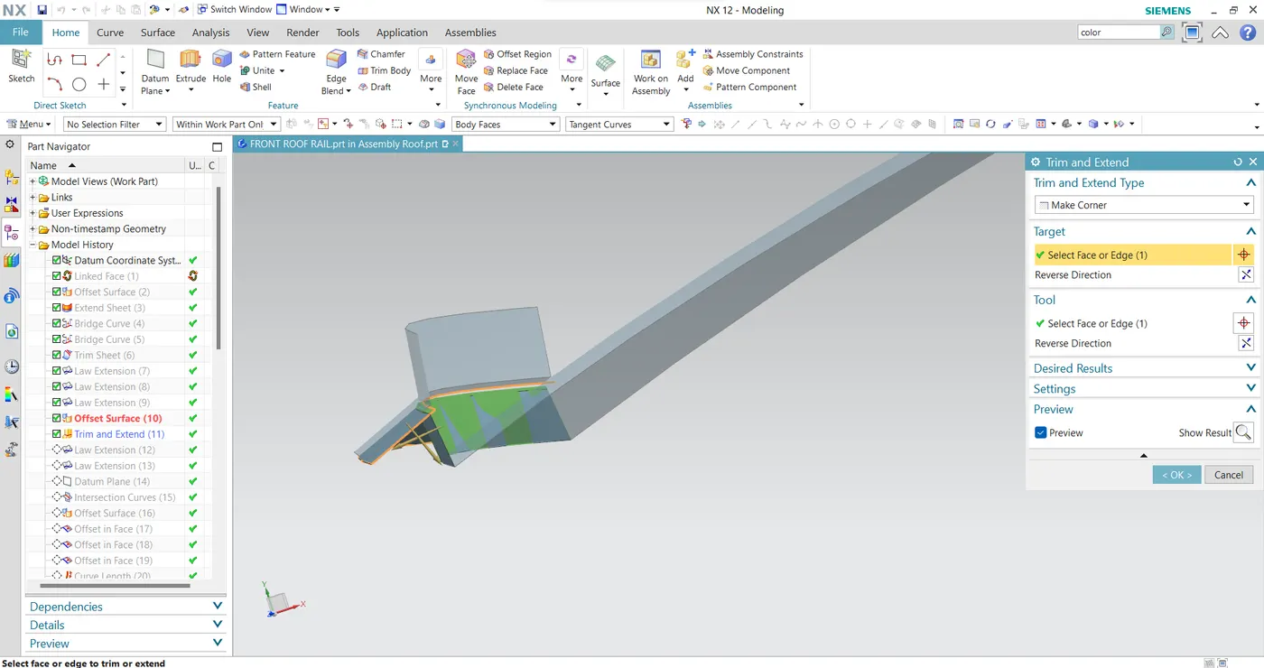
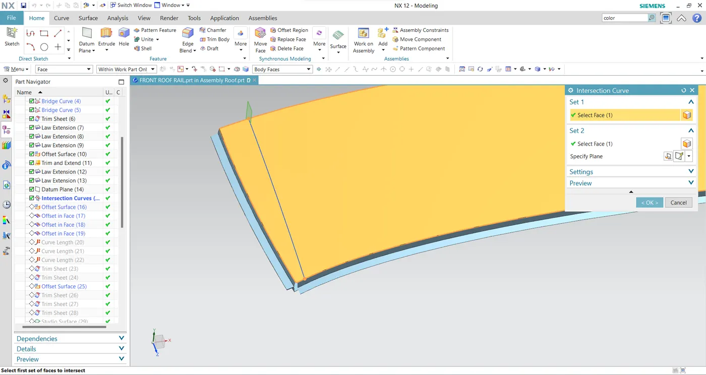
- create datum plane at the edge of the class A surface at the distance of 80mm.
- By using intersection curve create curve at the datum plane.
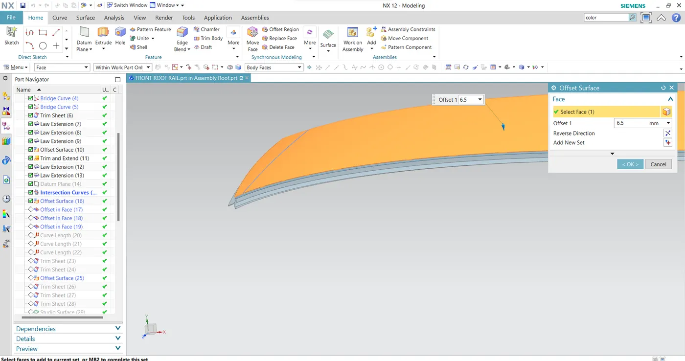
- offset the surface for 6.5mm using offset in surface.
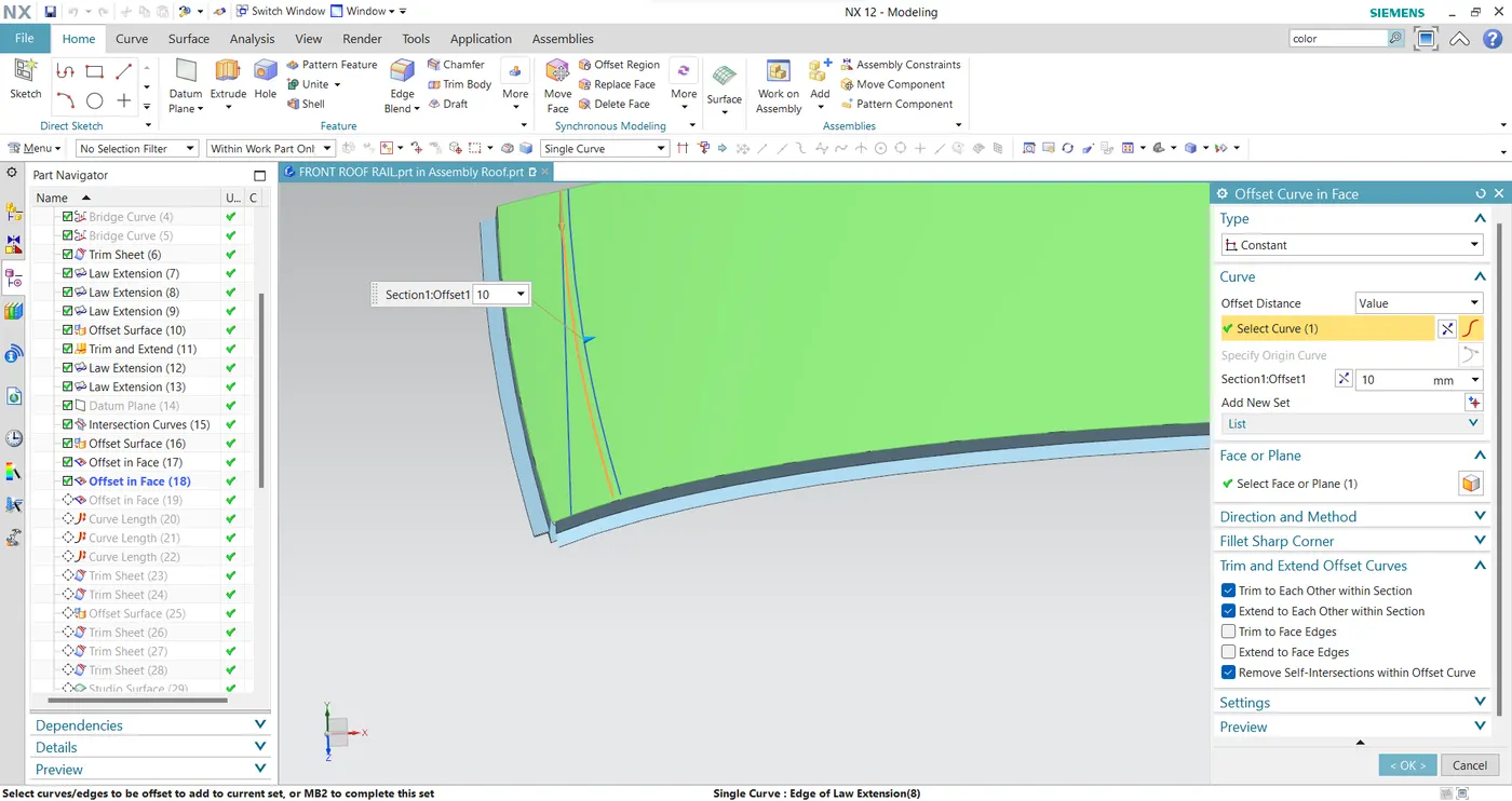
- offset the intersection curve for 10mm using offset curve in face.
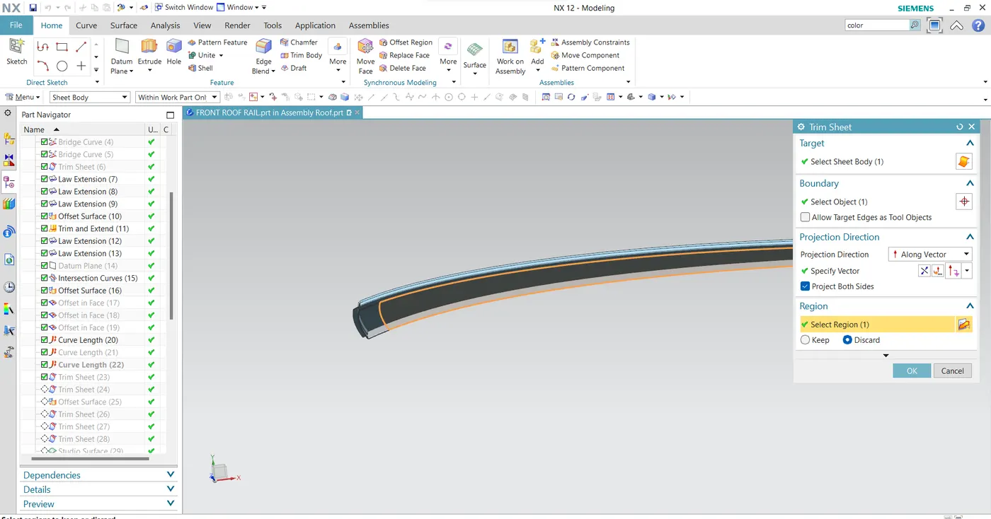
- trim the surface with respect to offset curve in face.
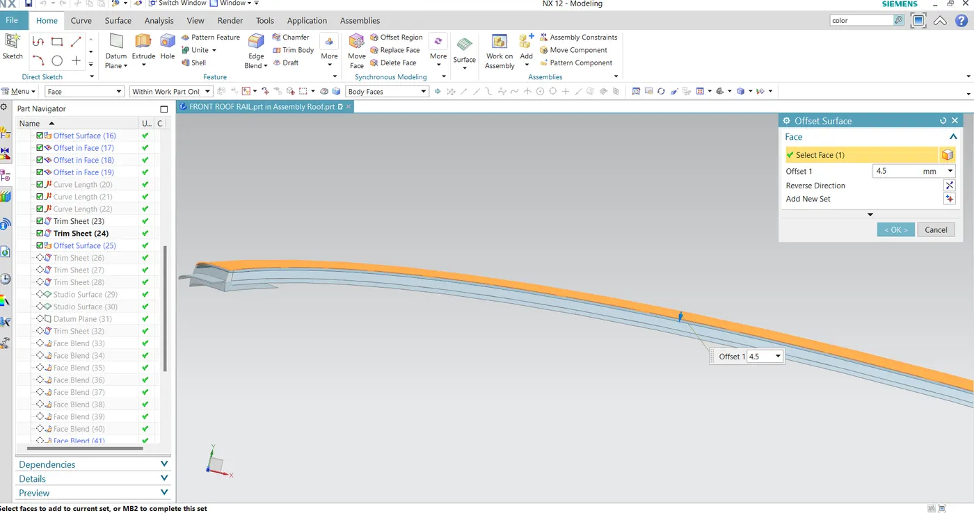
- then offset the surface for 4.5 mm using offset surface.
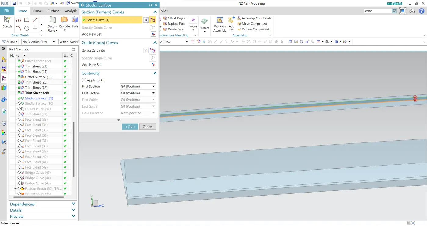
- create the studio surface in between trimed surface as shown in fig.

- create the datum plane on surface and trim the surface with respect to datum plane as shown in fig.
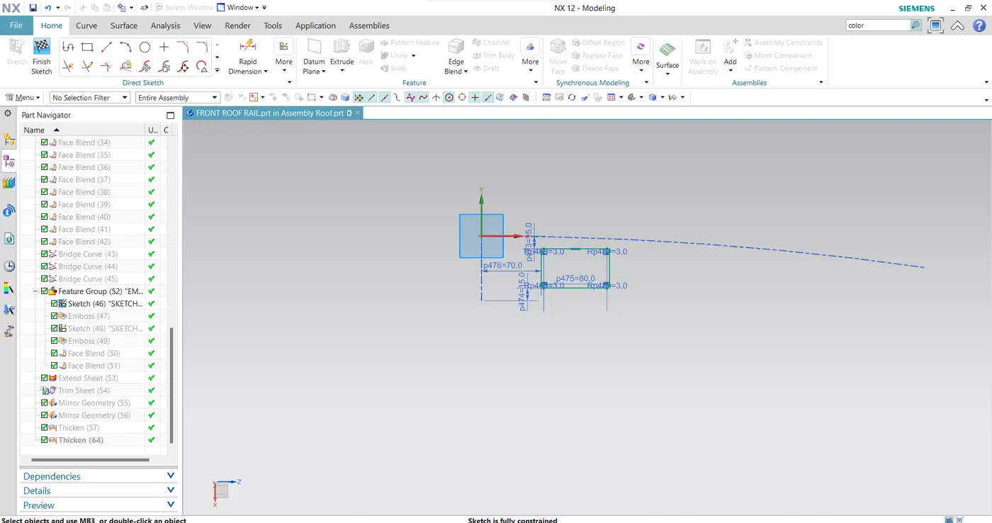
- create a sketch on law extenction os shown in fig .
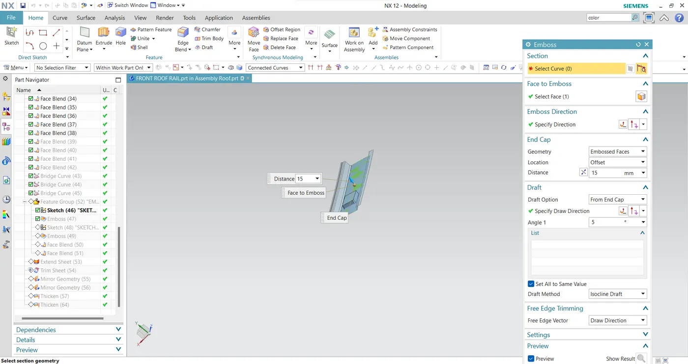
- provide the emboss to the sketch which is drawn on the above sketch as shown.
- after emboss is created ,then blend the edges of emboss and edges of the surface.
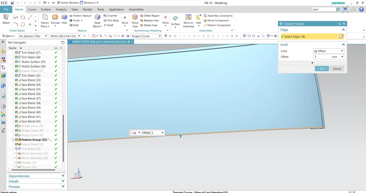
- extend the surface by the using extend sheet as shown in above fig.
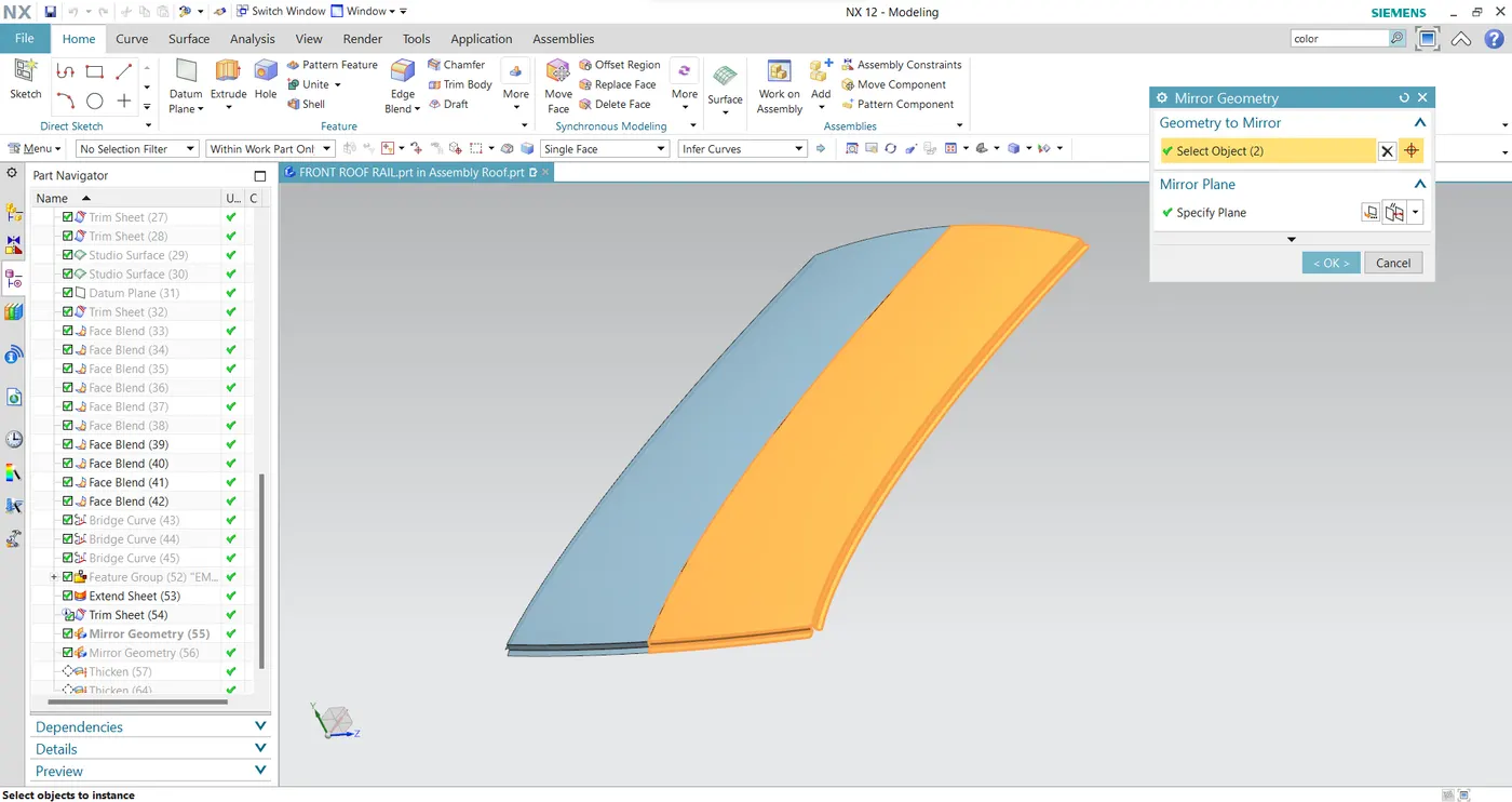
- then mirror the surface using mirror geometory.
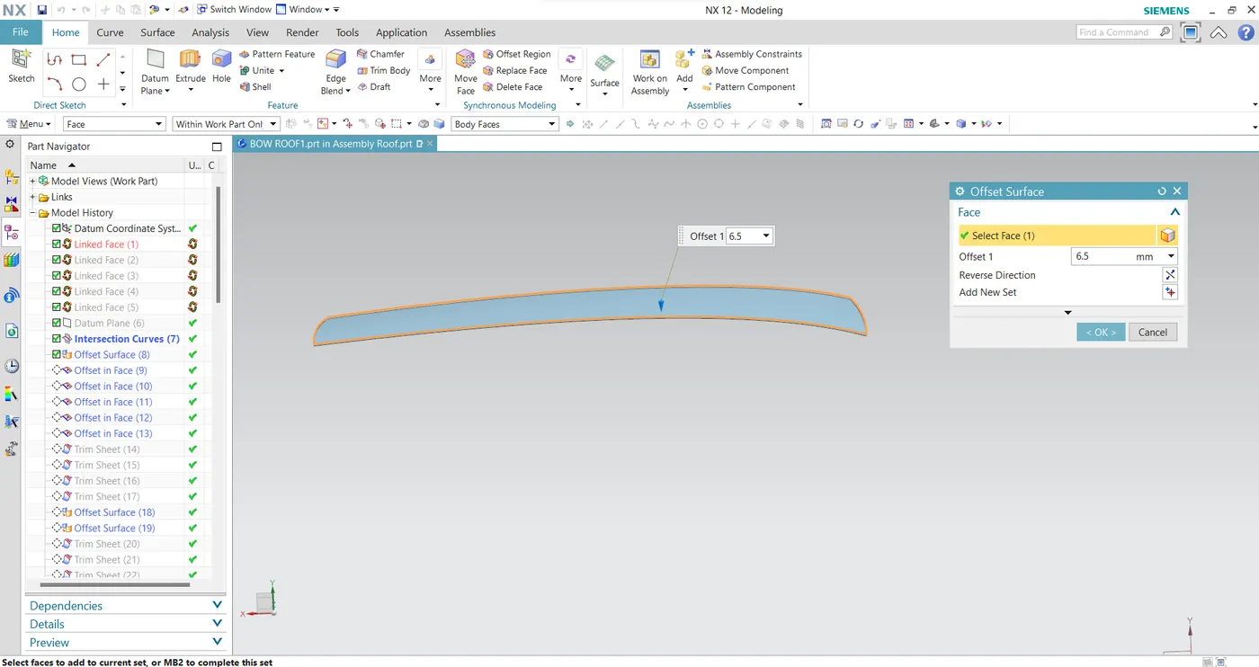
- first offset the class A surface for 6.5 mm,12mm,20mm using offset surface.
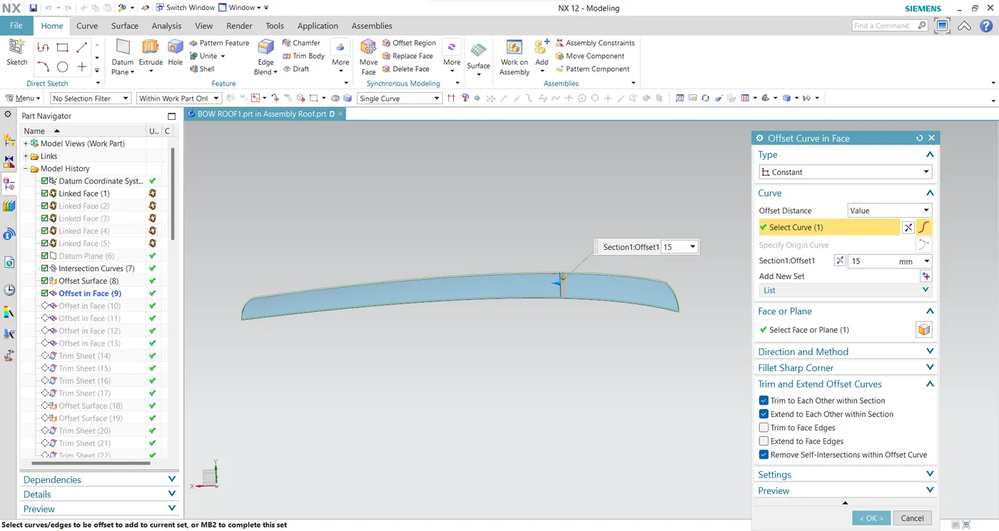
- create the intersection curve on the class A surface and offset the curve 15mm,30mm,40mm,55mm,70mm by using offset in face.
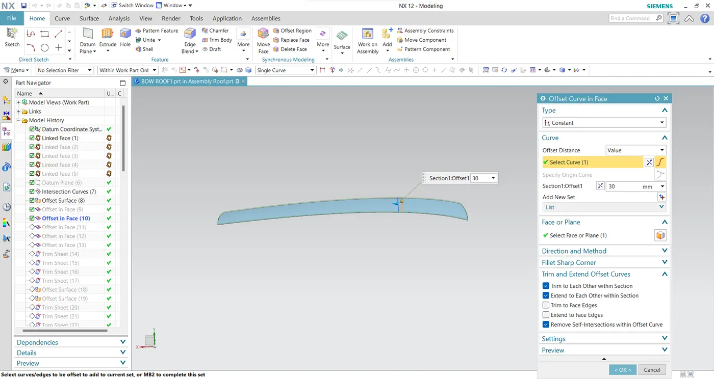
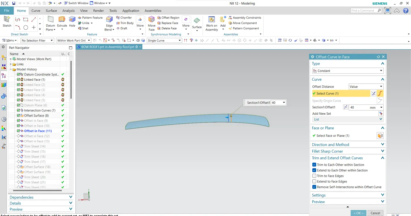
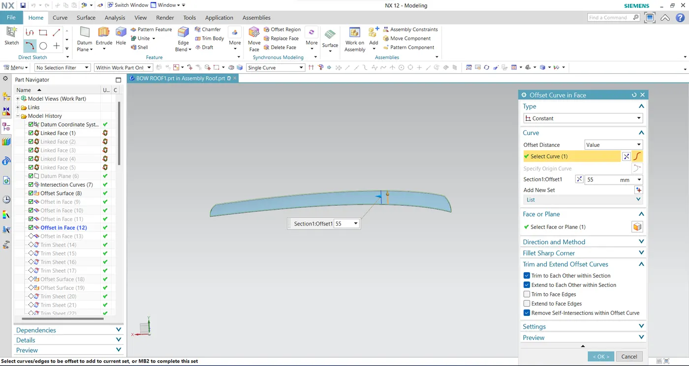
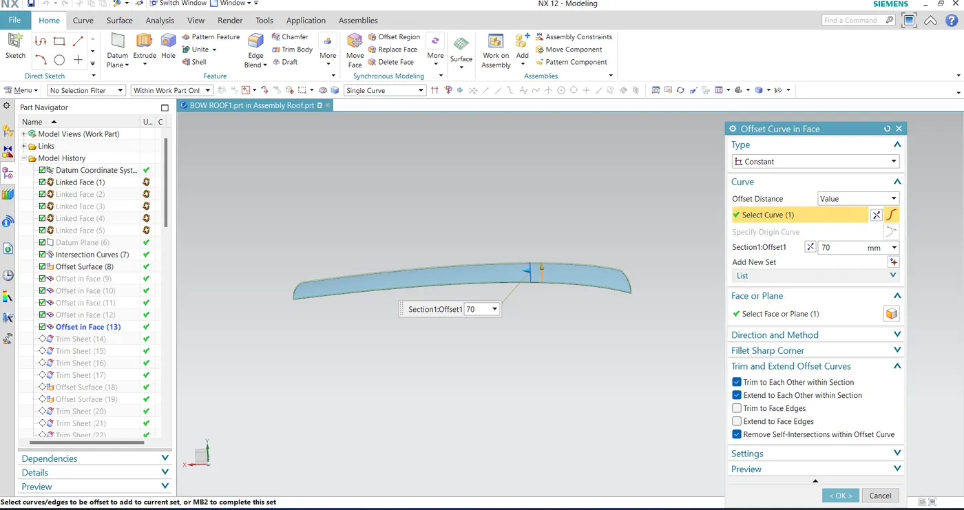
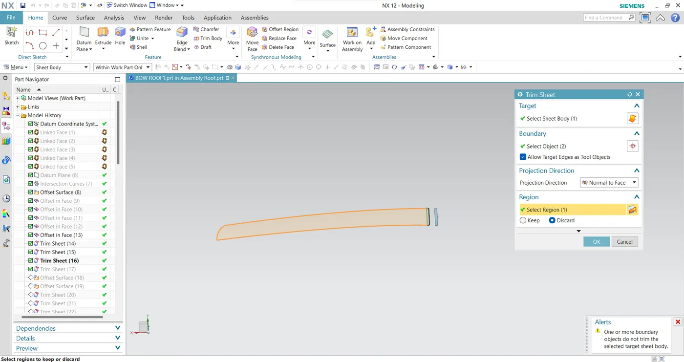
- trim the surface by using curves which as been created from offset in face and intersecting curve.
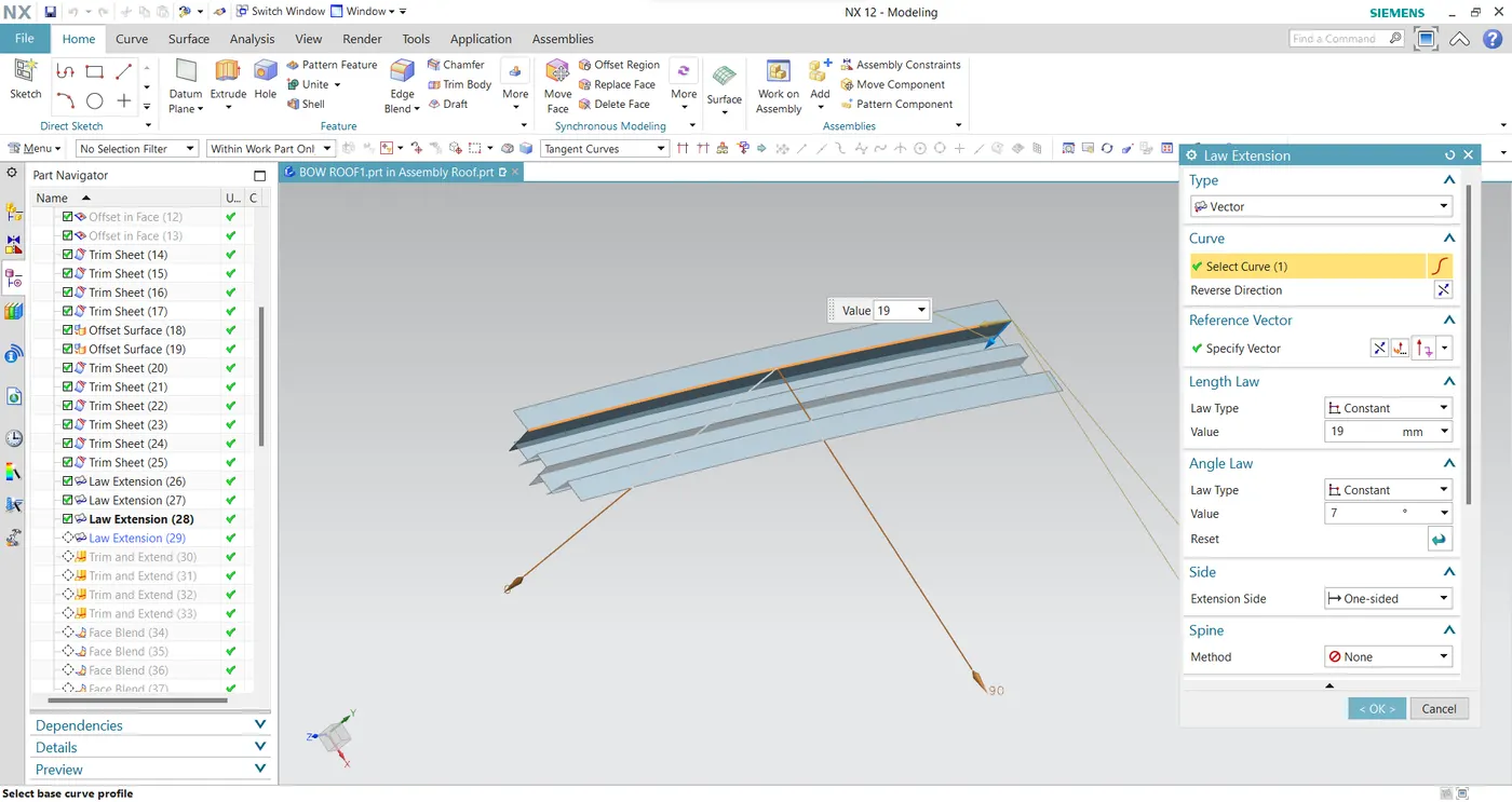
- law extend the surface by using law extension .
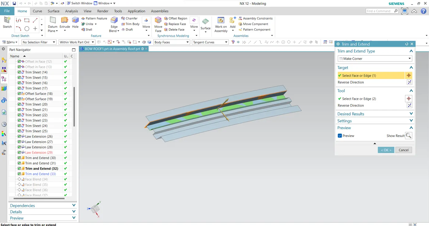
- trim the law extended surface and the timed surface using trim and extend.
- face blend trimed surface using face blend.
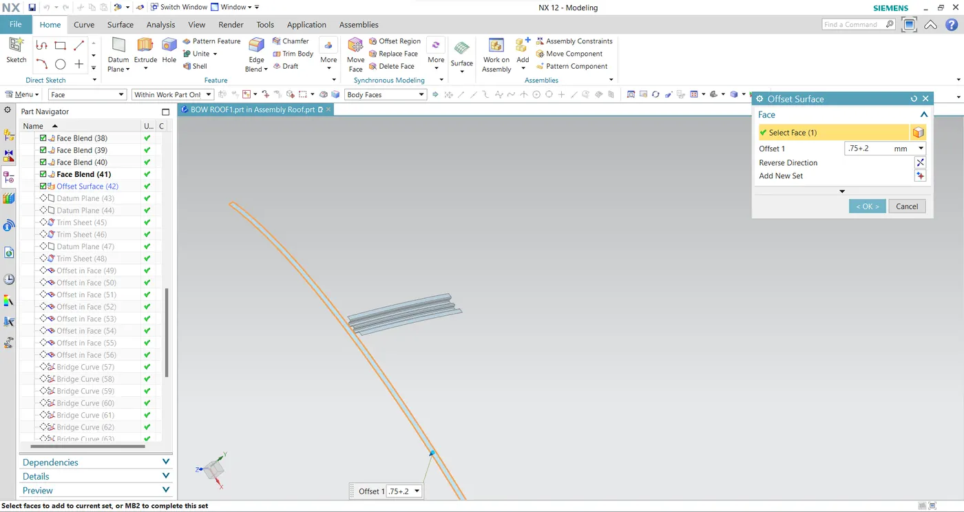
- offset the surface for 0.75+0.2mm using offset surface.
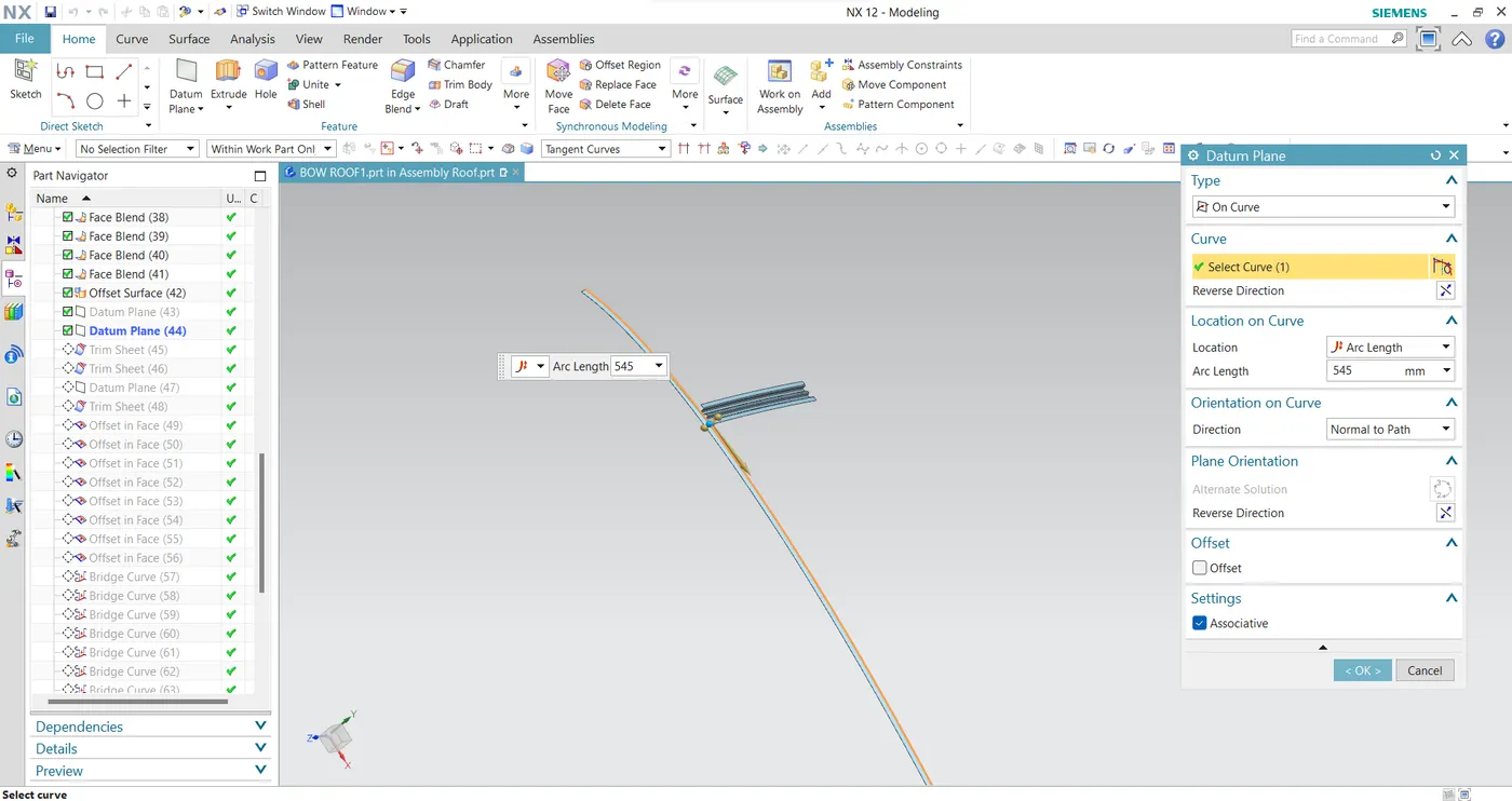
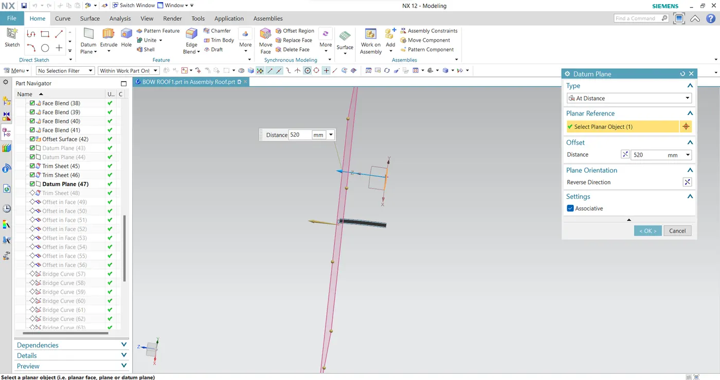
- create the planes at the ends of the surface datum plane.
- trim the offset surface which respect to datum plane using trim sheet.
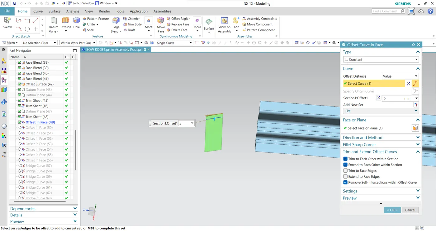
- offset the curve by using offset curve in face.
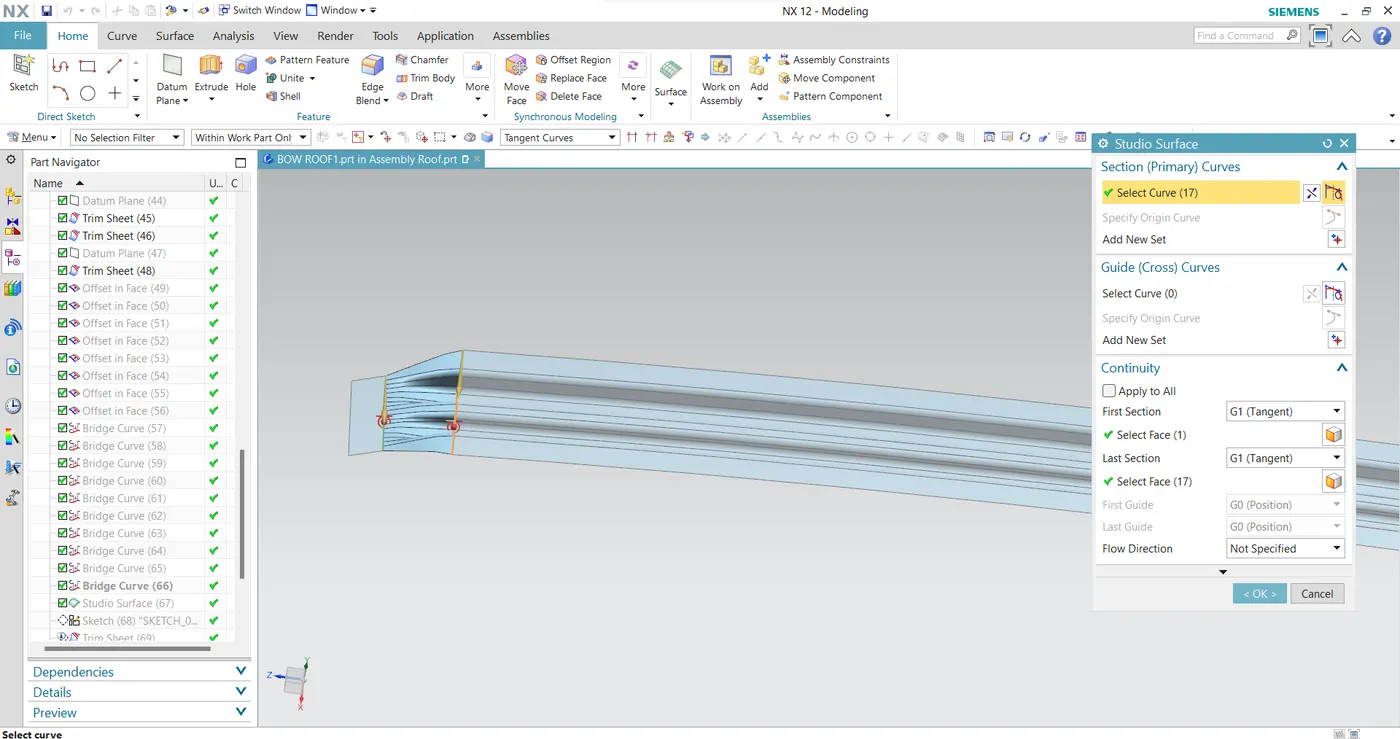
- create the bridge curve from the lower surface to the upper surface.
- create the surface between lower surface to upper surface by using studio surface.
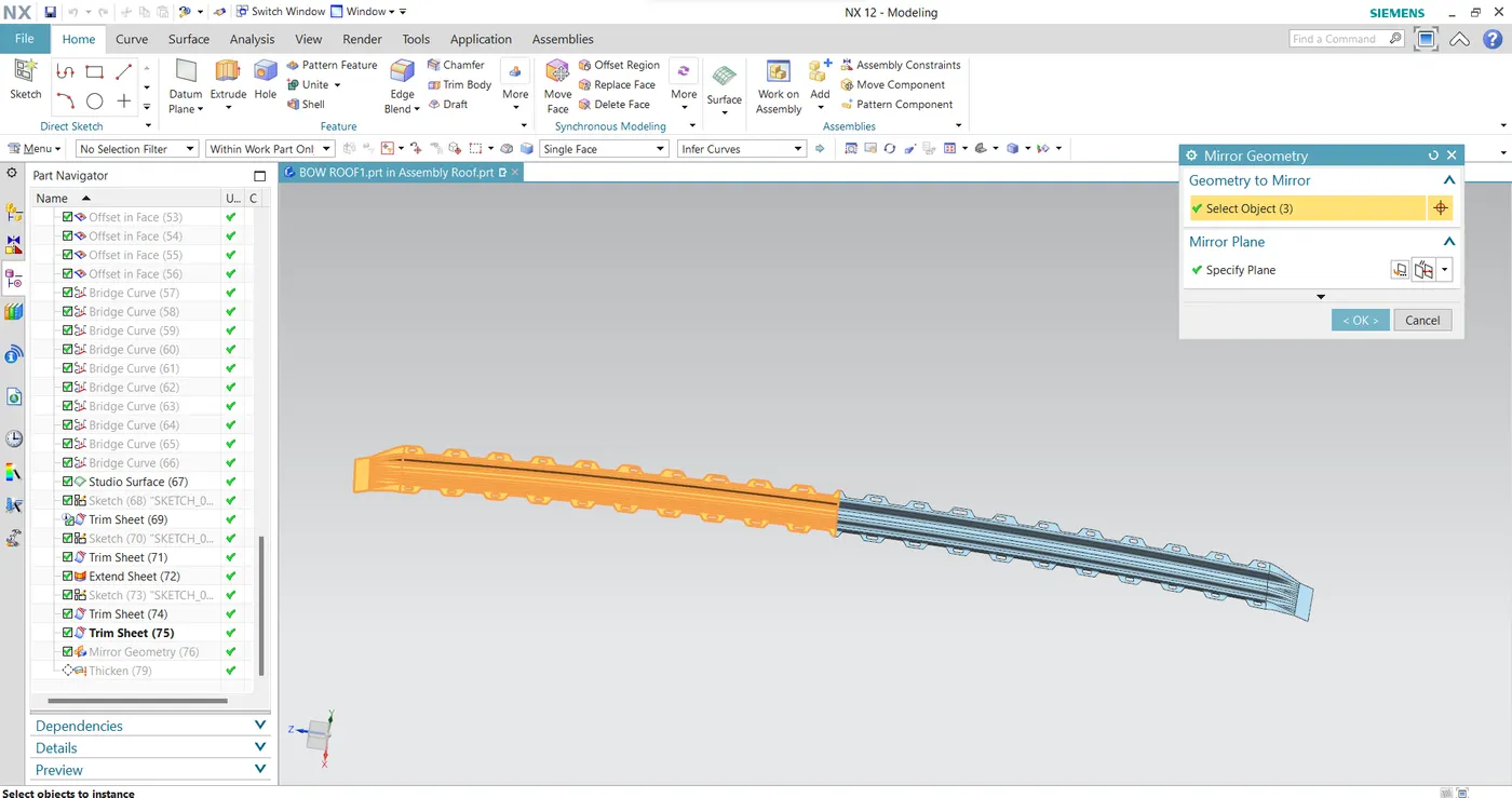
- mirror the final surface using mirror geometry and thicken the mirror surface using thicken .
BOW - ROOF PREDUCTION FORMULA :-
W = [1.73 x 10^(-3) x L] + [1.85 x 10^(-8) x (R^2)/t] + [ 1.10x10^(-3) x l] - 2.68
L = 2033.9065mm
Rx = 200.2917mm
Ry = 201.7366mm
R = 2(Rx*Ry)/(Rx+Ry)
R =2(200.2917* 201.7366)/(200.2917+201.7366)
R = 201.01155
t = 0.75 mm
I = 438.2321mm FRONT ROOF RAIL TO BOW RAIL 1.
I = 352.2896mm BOW RAIL 1 TO CENTER RAIL.
I = 457.2952mm CENTR RAIL TO BOW RAIL 2.
I = 353.7589mm BOW RAIL 2 TO REAR ROOF RAIL.
W = (1.73 10^(-3)*2033.9065)+(1.8510^(-8) *(201.01155^2)/0.75)+(1.10*10^(-3)*438.2321)-2.68
W = 1.3217
BOW RAIL 1 TO CENTER RAIL
W =1.2271
CENTER RAIL TO BOW RAIL 2
W = 1.3429
BOW RAIL 2 TO REAR ROOF RAIL
W = 1.2287
SNOW LOAD PREDUCTION FORMULA :-
Qr = [Iy x t2] / [α x s x [(Rx + Ry)/2]2 x 10-8]
t =0.75mm
LY = 1969.8472 mm
LX1 = 1137.802 mm BETWEEN FRONT ROOF RAIL AND BOW 1.
LX2 = 1089.3106 mm BETWEEN BOW 1 AND CENTER ROOF RAIL.
LX3 = 1062.3723 mm BETWEEN CENTER ROOF RAIL AND BOW 2.
LX4 = 1047.7186 mm BETWEEN BOW 2 AND REAR ROOF RAIL .
Y1= 531.3619mm
Y2 = 961.094mm
Y3 = 1494.3579mm
Y4 = 1969.8479mm
CASE 1
L1 = 531.3619 mm
L2 = 429.7327mm
CASE 2
L1 = 429.7327 mm
L2 =533.2632 mm
CASE 3
L1 =533.2632 mm
L2 =475.4893mm
RY1 = 2761.5317 mm RX1 = 4423.4465 mm
RY2 = 6291.2933 mm RX2 = 3773.6283 mm
RY3 = 11043.5828 mm RX3 = 4272.8359mm
RY4 = 16489.2567mm RX4 = 3989.9338mm
s = L1/2 + L2/2
S1 = 531.3619/2+429.7327/2 =480.5473
S2 = 481.49795
S3 = 504.37625
My = Y(Ly-Y)
MY1 = 531.3619(1969.8472-531.3619)
MY1 = 764356.2821
MY2 = 969506.6480
MY3 = 710551.19182
MY4 = 0
α = My x Lx2 x 10-12
α1 = 764356.2821* 1137.802*1O-12
α1 = 0.0008696861
α2 = 0.0010560939
α3 = 0.0007548699
IY1 = 4.3064
Qr = [Iy x t2] / [α x s x [(Rx + Ry)/2]2 x 10-8]
Qr = [4.3064*0.752] /[0.0008696861*480.5473*[(4423.4465+2761.5317)/2]2 x 10-8]