Roof Design
Objective:
To design car roof with essential flanges and reinforcements like ditch area , front roof rail , bow roofs, central roof rail for the the given styling surface using NX CAD.
To Find moment of inertia and section modulus for Bow roofs , central roof rail . front roof rail and rear roof rail and Perform the draft analysis for each reinforcements.
Introduction:
An automobile roof or car top is the portion of an automobile that sits above the passenger compartment, protecting the vehicle occupants from sun, wind, rain, and other external elements.
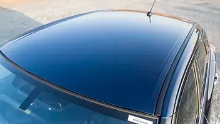
In the past roof was introduced as cover for passenger compartment but later on, it also used as a luggage carrier, sunroof and in recent past years with the introduction of the solar panelled electric vehicle got a major boost in the automotive industry.
Roof has the following functions:
- protects from external damage
- prevents passenger and vehicle from accidents
- luggage carrier
- design of the roof also affects in giving aerodynamic shape to vehicle
- sunroof
- solar panelled roof in EV
Since the roof has numerous functions so the roof has to be stronger enough to withstand the damage experienced by it. To have good strength and stiffness, the roof is made with different components such as front roof rail, rear roof rail, bow roofs, etc.
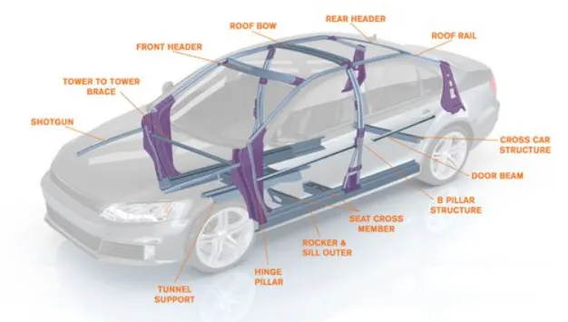
Front Header is the sheet metal part that supports the roof panel at front.
Rear header is the sheet metal part that supports the roof panel at the rear end.
The center roof bow is present around the center part of the roof (not necessarily exact center) and supports the central portion of the roof panel.
Assembly process:
Mastics are introduced between the roof outer panel and the reinforcements for joining . where ever the mastic are introduced there is remarkable improve of the strength.
Spot welding is also introduced to join the reinforcements and the outer panel.
Roof Test Analysis:
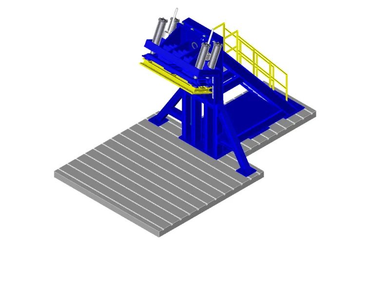
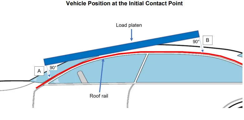
Roof strength evaluations are conducted on a quasi-static test system.
The system consists of an upright assembly and an attached loading head that can be fixed at varying
heights from the ground and at pitch angles ranging from −5 to +5 degrees to accommodate testing on the
driver or passenger side.
The roll angle is permanently fixed at 25 degrees.
Four hydraulic actuators control the movement of the platen along two linear guides.
The entire system is mounted on a T-slot bed plate anchored to the floor of the test facility.
Two I-beams are mounted on the bed plate perpendicular to the longitudinal axis of
the platen. The vehicle, with the attached rocker panel support system, is placed on these beams.
Once the vehicle is positioned correctly, the rocker panel supports are clamped to the two perpendicular Ibeams, and the beams are marked to confirm that the vehicle position is maintained during the test. For
body-on-frame vehicles, the frame is supported to prevent the weight of the chassis from stressing the
body at the body mounts.
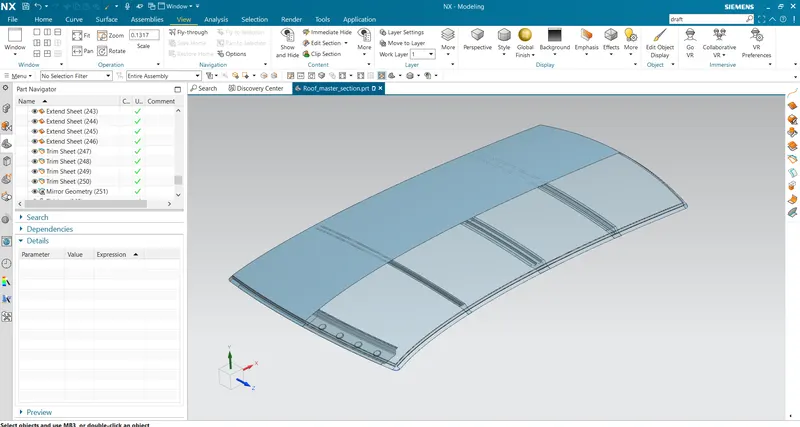
REINFORCEMENTS GIVEN:
Full roof section
Isometric view:
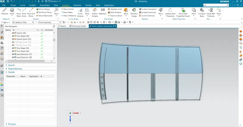
Top view:
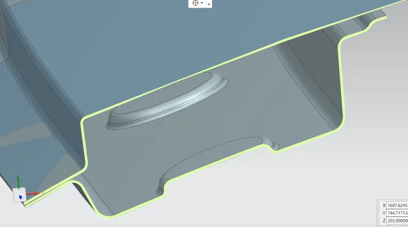
Front Header:
Front roof rail is the one which joins the wind shield glass , body side outer and the inner panel also. Here the front roof rail is designed based up on the master section given.
Front and rear bow:
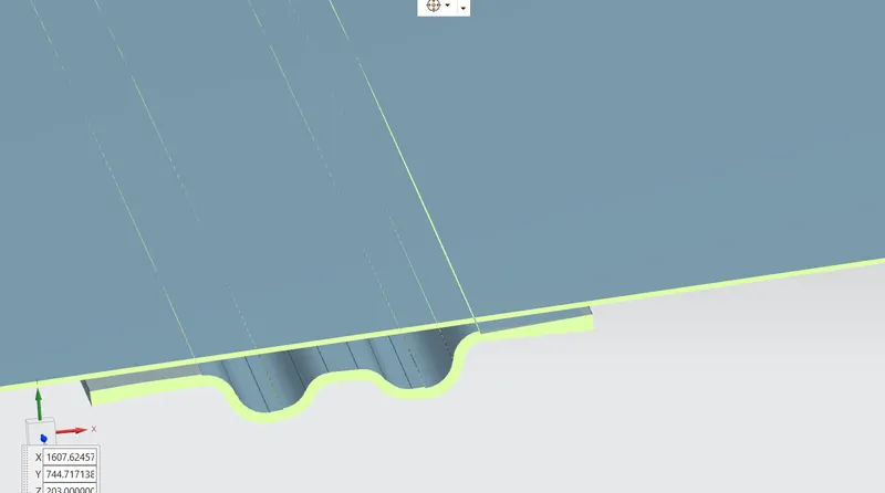
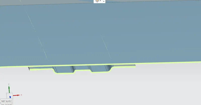
The bow roofs are give to improve the torsional stiffness and load bearing capacity of the roof structure . The number of bow roof present is depends on the overall size of the roof . Presently in this project two bow roofs are added. Both are shown below.
Central bow:
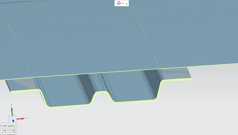
central roof rail helps in providing effectively support to the flat area of the roof as it is more susceptible to failure under the action of load . Generally central roof rail is placed at the center of the roof which is connected to the B-pillar support structure . This central roof rail helps in adding the strength to the roof during the rool over test.
Draft Analysis:
A draft analysis is used to see if the draft of a part is sufficient for the molding process and if the part will separate correctly from the mold. The draft refers to the angle between the face of a part and the direction of pull (refers to direction of the selected plane/face of a part) of each mold side.
The Draft Analysis command enables you to detect if the part you drafted will be easily removed. This type of analysis is performed based on color ranges identifying zones on the analyzed element where the deviation from the draft direction at any point, corresponds to specified values.
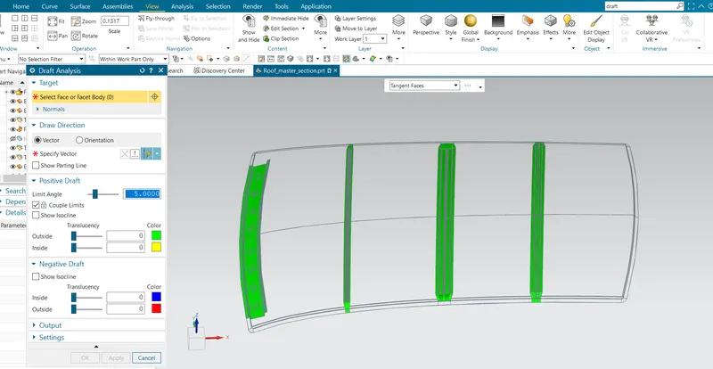
Minimum draft angle of 70 is considered for analysis . green colour infer on the parts that all face along the tooling direction has positive draft angle greater than 70 and passed in analysis
Green color coding in draft analysis resembles that the part will be easiily removed as shown below.
Section Inertia Analysis:
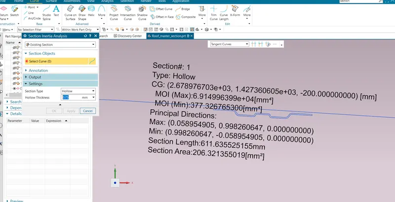
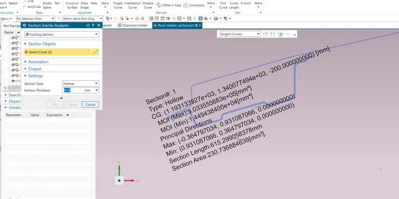
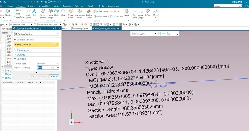
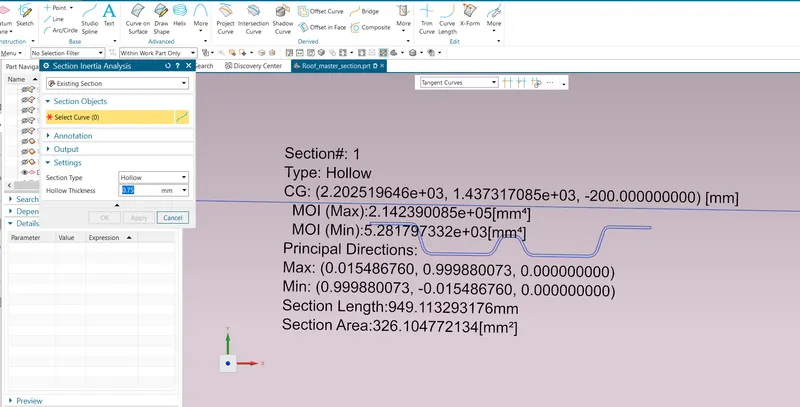
Section moment of inertia is used to predict the amount of deformation and deflection of a part. A higher moment of inertia is preferable as it reduces the amount of deflection for a given force. The thickness of the part and addition of flanges and embosses increase the section inertia of the part. Here the master sections of the roof and roof rails and their section analysis are given.
Hollow thickness : 0.75mm
Front header:
Front bow:
Centre bow:
Rear bow: