Roof Design
ROOF DESIGN
ROOF
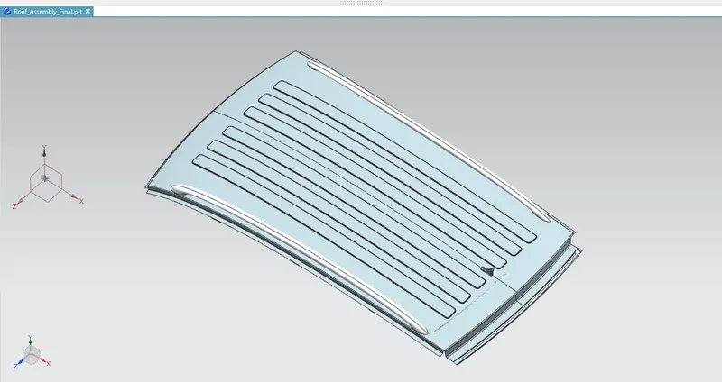
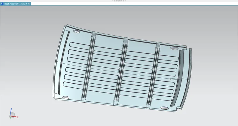
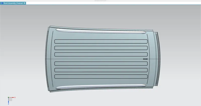
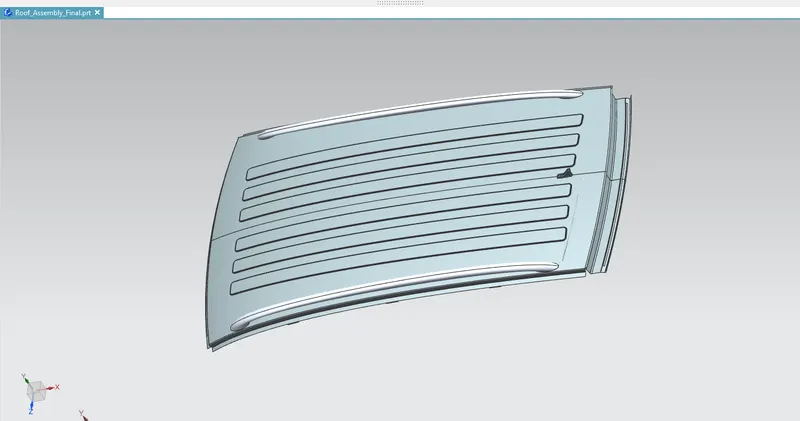
An automobile roof is the portion of an automobile that sits above the passenger compartment, protecting the vehicle occupants from sun, wind, rain, and other external elements. Though it just looks like a styling surface that protects from sun, wind and other elements, various environmental conditions are taken into account for designing of the same. Roof should be provided with proper reinforcements for strengthening. Vehicle roof can be subjected to high heat conditions or load during snowy conditions. To make the roof withstand these conditions, various calculations are done. This ensures the safety of the passengers in the vehicle.
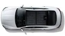
TYPES OF ROOF
- Convertible roofs
- Hardtops
- Sunroofs
- T-tops
- Targa tops
- Vinyl roofs
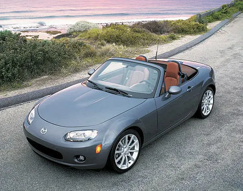
- Convertible roofs
A convertible or cabriolet is a passenger car that can be driven with or without a roof in place. The methods of retracting and storing the roof vary amoung eras and manufacturers.
- Hardtops
A hardtop is a rigid form of automobile roof, which for modem cars is typically constructed from metal. a hardtop roof can be either fixed, detachable for seperate storing or retractable within the vehicle itself.
- Sunroofs
A sunroof is a movable panel that opens to uncover a window in an automobile roof, allowing light and fresh air to enter the passenger compartment. Sunroofs can be manually operated or motor driven, and are available in many shapes, sizes and styles.
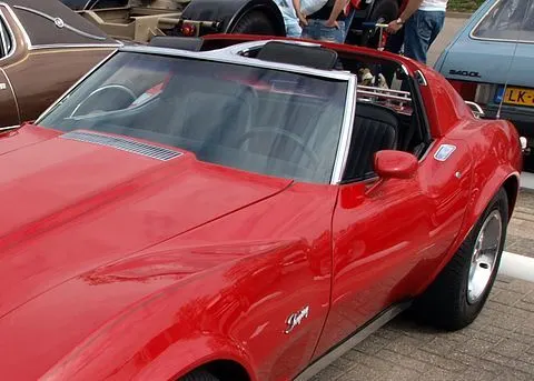
- T-top
A T-top is an automobile roof with a removable panel on each side of a rigid bar running from the center of one structural bar between pillars to the center of the next structural bar. The panels of a traditional T-top are usually made of auto grade safety glass.
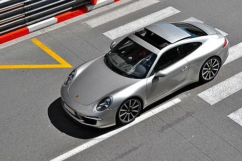
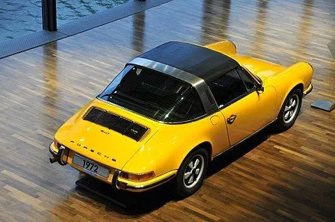
- Targa tops
Targa top, or targa for short, is a semi-convertible car body style with a removable roof section and a full width roll bar behind the seats. The term was first used on the 1966 Porsche 911 Targa, and it remains a registered trademark of PorscheAG.
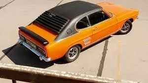
- Vinyl roof
Vinyl roof refers to a vinyl covering for an automobile's top.
DESIGN CONSIDERATIONS FOR A ROOF
- Visibility criteria
- Head clearance
- Curvature study
- Heat distortion and snow load criteria
- Draft analysis
MASTER SECTION
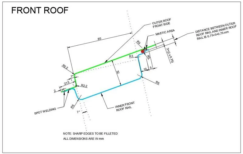
- Front Roof Rail
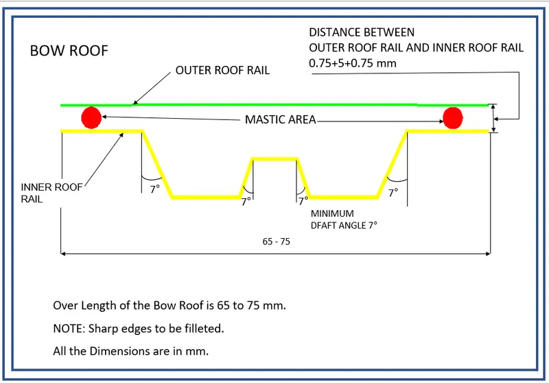
- Bow Roof Rail
- Center Roof Rail
- Rear Roof Rail
COMPONENTS OF ROOF
- Front Roof Rail
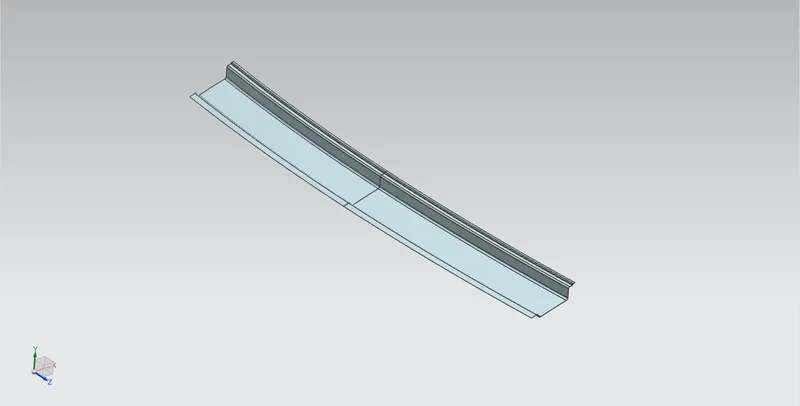
The front roof rail is located on the front of the roof where the wind shield joins with the roof. The visibility criteria and the head room clearance of the passenger are taken into consideration for the bottom flange. One end of the rail is joined using spot welding while the other end is joined with the roof using mastic sealants for increased strength.
- Rear Roof Rail
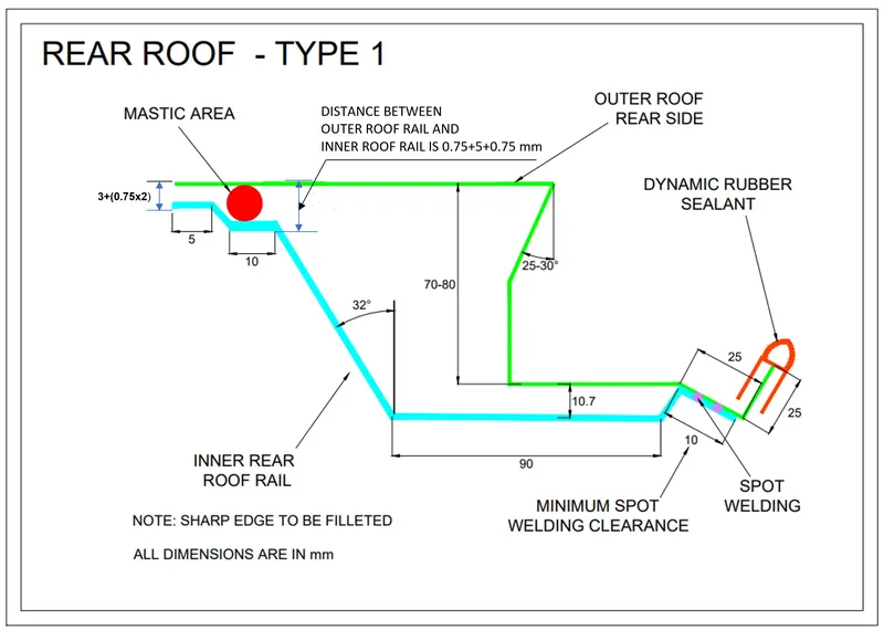
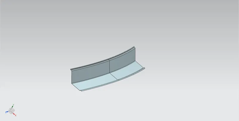
This roof rail joins with the back door and the roof. Inputs from the backdoor are taken into consideration for designing this roof rail. Here one end is joined using spot welding while the other end is joined using mastic sealants.
- Centre Roof Rail
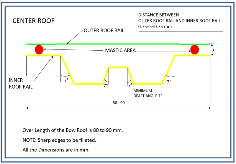
Centre Roof rail or the reinforcement centre is located at the centre of the roof . The cross section of this is more since it needs to provide more strength to the roof. Here both are ends are joined together using mastic sealants.
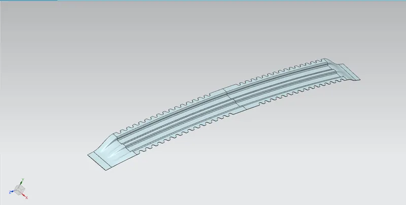
- Bow roof 1
Bow roof is an additional siffening member for the roof to increase the strength and so that it can satisfy the norms. Both the ends are joined together using mastic sealants to increase strenght and also since this would not affect the styling of the roof.
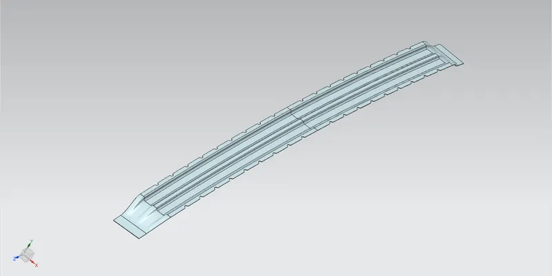
- Bow roof 2
This bow roof also have the same purpose as that of the first one. This one is located between the centre bow roof and rear roof rail.
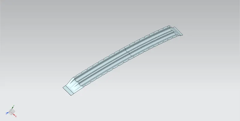
JOINING PROCESS
- Mastics are introduced between the roof outer panel and the reinforcements for joining where ever the mastic are introduced there is remarkable improve of the strength.
- Spot welding is also introduced to join the reinforcements and the outer panel.
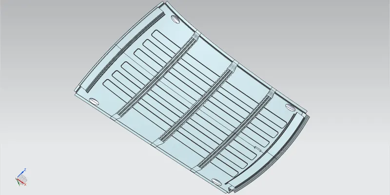
Ditch Area
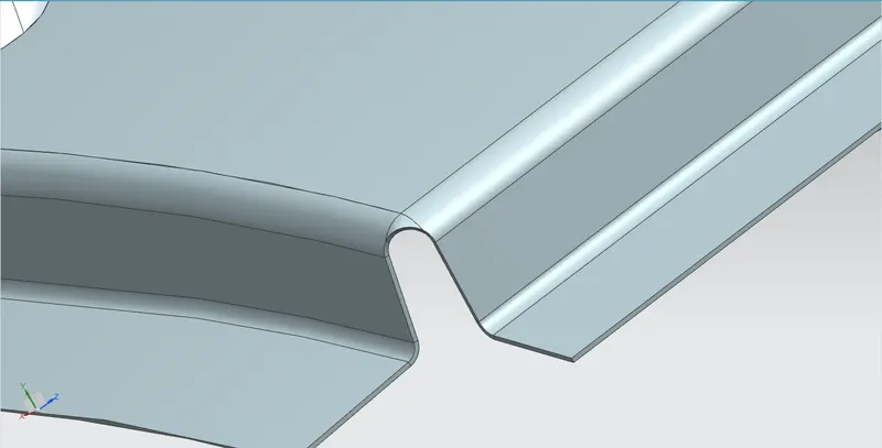
Ditch area is the extended portion of the roof styling surface which is used to mount the reinforcements and also ensures sealing between parts of the roof. Opening angle of ditch is 7 degrees.
ROOF CRUSH TEST
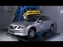
Roof crush test is the design given by the IIHS (Insurance Institute of Highway Safety). After analysing the many accidents IIHS has then fixed some regulations, that how to perform the crush test.
IIHS gives the rating based up on this test. For this they consider two points while giving the rating.
- How fast the car can reform to its original shape after the roll over.
- How deep is the protrusion after the roll over.
Goal of roof crush test :
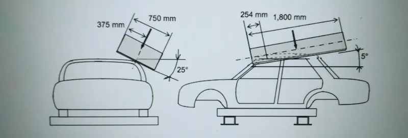
To minimize the protrusion into the occupant compartment, so that the seat belts and air bags can do their job in protecting the occupant.
METHOD OF APPLYING THE FORCE:
The load is applied in such a way that 50 is tilted from the front end to the rear end and the load will be in 1800 mm in length and 750 mm in width. The load is applied at the position of 250 from the flatness of the roof. The load is applied on the roof for almost 120 sec and the crush speed at which the load applied is 13 mm/sec or less than.
ROOF BOW CALCULATION (CURVATURE STUDY)
The Roof bow Calculation is also known as Curvature study. It is an analysis performed to validate and determine weather the bow roofs and the roof rails are positioned correctly in accordance with the curvature and the length of the roof outer panel.
This study is done based on the following criteria:
- Heat Distortion Criteria
- Snow Load criteria
HEAT DISTORTION CRITERIA:
The heat radiating from the sun causes the roof of the car to change in the metallic regions. The heat distortion study plays a major role in sheet metal usage. heat distortion temperature is a temperature limit above which the material cannot be used for the structural applications. This study is used to predict the heat distortion temperature at where the material starts to soften when exposed to a fixed load at elevated temperature. In order to avoid bending or damages on the roof, based on the heat distortion temperature, this study will predict the bow roof position which helps to strengthen the roof.
W = [1.73 x 10(-3) x L] + [1.85 x 10(-8) x (R2)/t] + [ 1.10x10(-3) x l] - 2.68
Where,
L = Roof Length in X-Direction[mm] (Roof dimension in 0-Y)
R = Roof curvature
R = 2(Rx*Ry) / (Rx + Ry)
Rx = X curvature
Ry = Y curvature
t = Roof plate thickness [mm]
l = Bow Roof Span [mm]
Judgment Condition
OK< 2.7
Calculation
- Create a sketch on top roof and drawn a horizontal line at the centre.
- Then offset this line below 300mm and called it as -3Y line.
- From the _3Y line offset 100 mm above and below and convert all these line into reference lines.
- Draw the vertical lines at the middle of the each reinforcements and offset it to 100 mm both sides.
- Intersection point is created where the lines are met.
- Project these points to the outer roof panel.
- Now draw the arc by connecting three points and measure the min radius value.
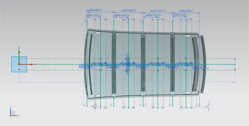
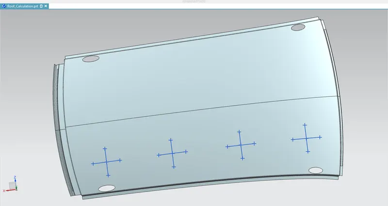
The values are tabulated and 'W' is calculated.
| Roof Rails | Rx (mm) | Ry (mm) | R (mm) | L (mm) | I (mm) | t (mm) | W | RESULT |
| FRR - BR1 | 5741.22 | 2420.84 | 3405.65 | 2033.7 | 380.89 | 0.75 | 1.54 | OK |
| BR1 - CRR | 4972.43 | 6196.88 | 5517.53 | 2033.7 | 433.41 | 0.75 | 2.06 | OK |
| CRR - BR2 | 3984.99 | 10542.86 | 5783.81 | 2033.7 | 436.91 | 0.75 | 1.14 | OK |
| BR2 - RRR | 3248.43 | 14798.58 | 5327.43 | 2033.7 | 346.61 | 0.75 | 1.19 | OK |
SNOW LOAD CRITERIA
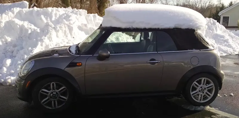
This test is done to know how is the roof behaving when there is a snow over. Normally due to the snow weight the dent will happen. But the roof should be designed in such a way that when the snow is removal the roof should go it its original position. This is the basic requirements for snow load criteria.
Qr = [Iy x t2] / [α x s x [(Rx + Ry)/2]2 x 10-8]
Where,
α = My x Lx2 x 10-12,
My = Y(Ly-Y)
t = Roof plate thickness [mm]
Ly = Distance between the front and rear roof Rails on the Vehicle along with 0Y[mm]
Length of Roof panel with the centre point between Roof rail Front /Rear as the reference point of the front and the rear.
Lx = Distance between the Left and Right end of the roof on the Roof BOW [mm]
Width of the roof panel exposed on the surface.
Y = Distance Front Roof Rail to Roof BOW [mm]
s = Distance for which Roof BOW bears divided load [mm]
s = L1/2 + L2/2
Iy = Geometrical moment of inertia of Roof BOW (Y cross-section) [mm4]
Rx = Lateral direction curvature radius of roof panel Y cross-section on Roof BOW [mm]
Roof panel curvature Radius of the Length Lx in Front view
Ry = Longitudinal Direction curvature radius of the Roof panel X cross-section on Roof BOW [mm]
Roof panel X curvature radius of length s in Side view
Judgement condition
Qr ≥ 3.1
250 ≤ s ≤ 380
Calculation
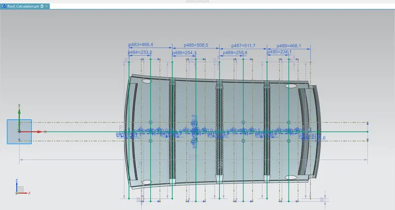
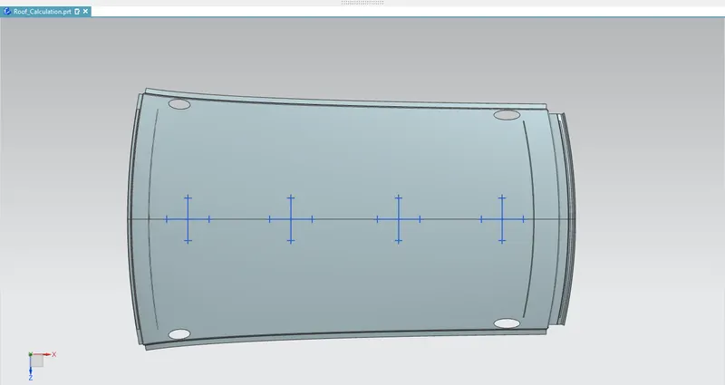
- Create a sketch on top roof and drawn a horizontal line at the centre.
- Offset this line to 100mm on both sides.Convert all these line into reference lines.
- Draw the vertical lines at the middle of the each reinforcements and offset it to 100 mm both sides.
- Intersection point is created where the lines are met.
- Project these points to the outer roof panel.
- Now draw the arc by connecting three points and measure the min radius value.
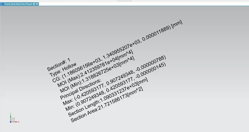
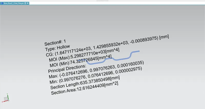
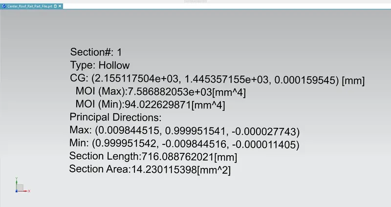
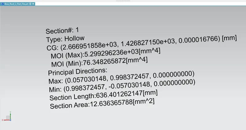
Section Inertia Analysis
- Front Roof Rail
- Bow Roof 1
- Center Roof Rail
- Bow Roof 2
- Rear Roof Rail
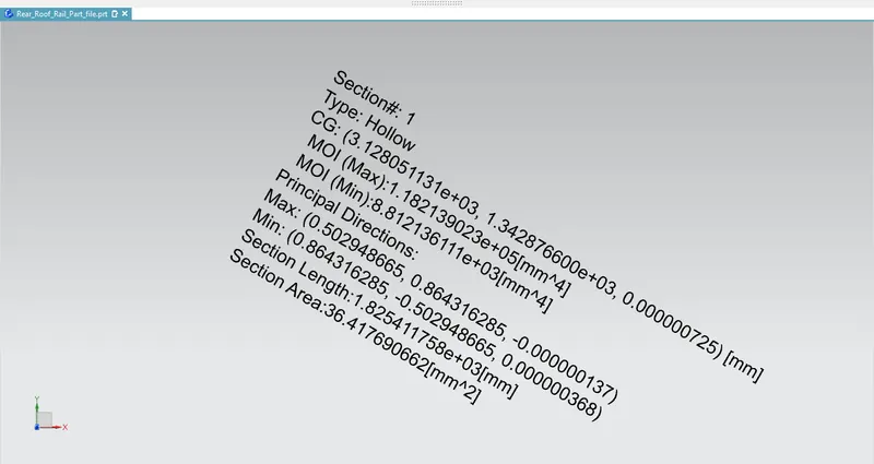
The values are tabulated and 'Qr' is calculated.
| Roof Rails | Iy (mm4) | Lx (mm) | Ly (mm) | Y (mm) | L1 (mm) | L2 (mm) | Rx (mm) | Ry (mm) | t (mm) |
| FRR - BR1 | 8.8121 | 1040 | 2033.7 | 466.4 | 466.4 | 508.5 | 4613.38 | 2486.05 | 0.75 |
| BR1 - CRR | 94.0226 | 1164.29 | 2033.7 | 974.9 | 508.5 | 511.7 | 3764.31 | 6101.39 | 0.75 |
| CRR - BR2 | 74.3257 | 1099.95 | 2033.7 | 1486.6 | 511.7 | 468.1 | 4271.72 | 11028.71 | 0.75 |
| BR2 - RRR | 8.8121 | 1058.8 | 2033.7 | 1954.7 | 468.1 | _ | 3955.14 | 16633.71 | 0.75 |
| Roof Rail | My | α | S | Qr | RESULT |
| FRR - BR1 | 730988.7 | 0.7906373 | 480.8 | 4.021036 | Ok |
| BR1 - CRR | 651577.7 | 0.7896531 | 377.42 | 3.154923 | Ok |
| CRR - BR2 | 813318.9 | 0.9840265 | 352.57 | 4.472219 | Ok |
Modifications
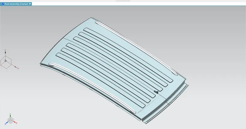
In order to strengthen the roof embosses are provided on the outer roof and the roof rails are adjusted.
Manufacturing technique:
The manufacturing process for car roof parts, comprises the following steps:
- Outer board machining process
Bar shaped assembly, ring-shaped component processing and roof cant rail processing technology, formed respectively.
- Outside plate process
The first step, open straight snips plate: first select applicable cold coiling specification, cold coiling is opened flat. Then according to production material specification, will open cold coiling after flat and be cut into into the iron plate of corresponding size. Finally the iron plate after shear is cleaned to iron filings. The first step, oil pressure, punch press: first iron plate is extended. Secondly to its trimming and punching. Then to its flanging and punching. Finally, after punching completes, it is carried out to the operation of side folding. Completed the making of outside plate.
- Bar shaped assembly and ring-shaped component process
The first step, blanking, stamps out iron plate the outline blank of many roof cant rails, a ring-shaped component and a bar shaped assembly> Second step, carries out annular punching to ring-shaped component. Bar shaped assembly and roof cant rail are carried out to bar shaped punching.
- Car roof anabolic process
The first step, by a plurality of M6 nuts of a side spot welding of ring-shaped component. By two M6 nuts of bar shaped assembly two ends spot welding. Second step, spots weld bar shaped assembly the opposite side of the corresponding nut of ring-shaped component. And circular groups and the punching of bar shaped assembly are aimed at. The 3rd step, is welded to ring-shaped component the inner side of outside plate. The 4th step, spots weld roof cant rail the inner side of outside plate. Finally car roof integral body is carried out to sanding thorn and ending.
DRAFT ANALYSIS
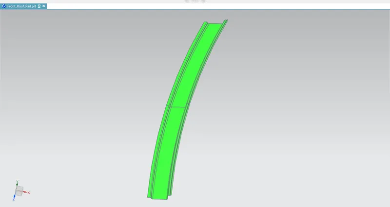
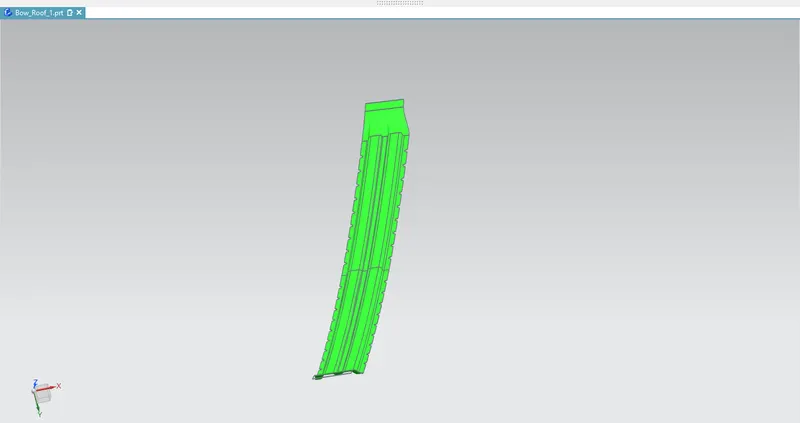
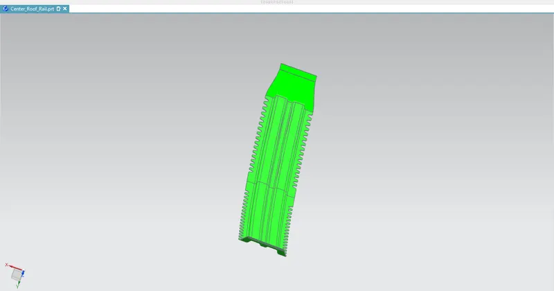
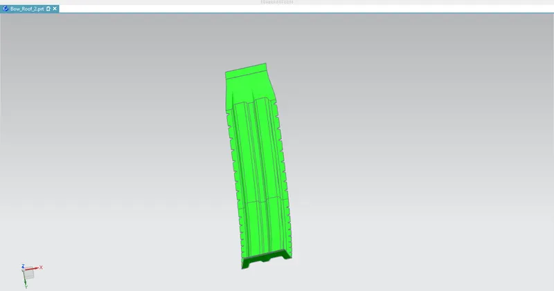
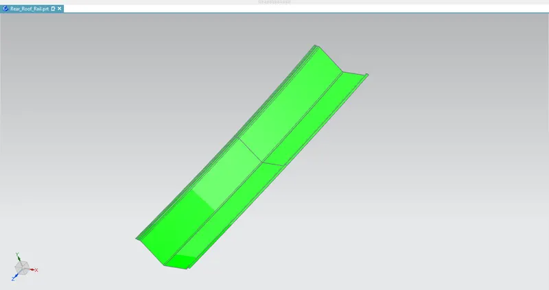
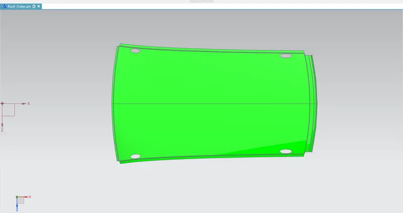
The Draft Analysis command enables you to detect wheather the part model created is manufacturable based on the draft condition applied. This type of analysis is performed based on color ranges identifying zones on the analyzed element where the deviation from the draft direction at any point, corresponds to specified values. Minimum draft angle of 70 is considered for analysis green colour infer on the parts that all face along the tooling direction has positive draft angle greater than 70 and passed in analysis.
- Front Roof Rail
- Bow Roof 1
- Center Roof Rail
- Bow Roof 2
- Rear Roof Rail
- Outer Roof
CONCLUSION
Thus the various sections of the roof were designed according to the master sketch and curvature study was performed to validate the positioning of the bow roofs and the roof rails using Siemens NX CAD.