Roof Design
ROOF Design challange of a Car
so we can start or model in NX CAD, a skin data of roof is given with the question and we add this data to the assembly model and we extract the roof surface for our design purpose. so we extracted the main surface of roof and untrimmed the part which occupies the roof rails and for easy we will be working on the symmetric half portion of the roof face.
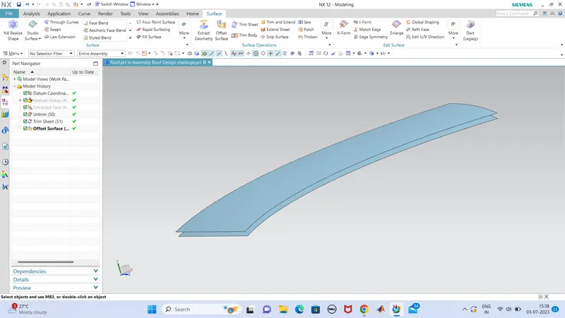
now we can start the designing in front rail portion of roof from the given data.
the front rail contain a inner portion and outer roof section also which occupies the wind shield portion seating. and the gap for mastix are also to be calculated.
so firstv worked on the outer roof part,which i used law extension to extend the sheet with a angle of 25 degree to frontward and of a length of 15 cm (which is aprox), we can change it after .
the a law extension of 21.5 mm which is parallel to the outer roof surface .so the portion of outer roof is completed for the seating of wind shield glass.
and a face extrusion of 32 mm towards downward from the outer roof is also made for the innner roof which is a part of front roof rail.
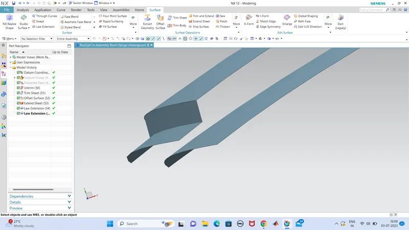
no we can work on the extruded face ,which i extended a little bit towards left side and a law extension is made at that edge at a angle of 65 degree (which i have calculated all the calculations corresponding to the figure) and for a free length.so i can trim after where i want to.and the .75 mm of two thickness plates and a gap of .2mm is made a gap btween these two face so a total of 1.7mm is offsetted from the upper surafce towards down and trimmed the inner panel at the intwersection.
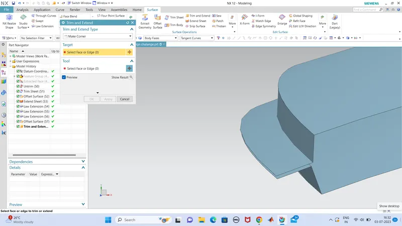
so the left portion of front rail is completed and the right end of the front rail is about a distance of 80mm and is trimmed and maded flanges like the same we have done in the left side as well.with the appropriate angle given. and the reamining portion of the sheet is trimmed off.
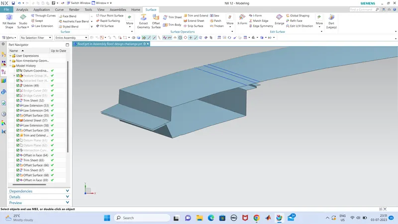
the 80mm is made by the datum plane and made an intersection on the plane and offset the curve of length of flange and made.
so now we can made the blends for the part at a proper dimentions.this is the inner panel portion shown below,
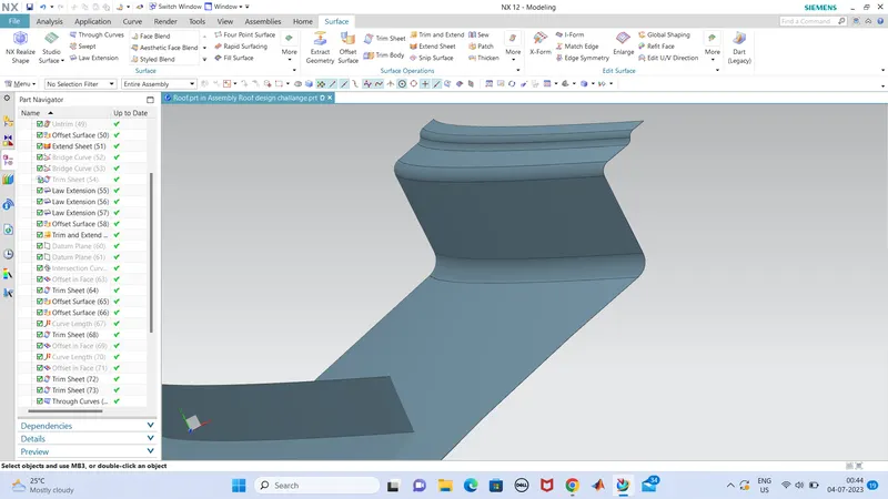
a side flange is made as the same dimentions and angle as equal to the front rail .which covers the inner panel.
anfd the corner is made connected by studio surface
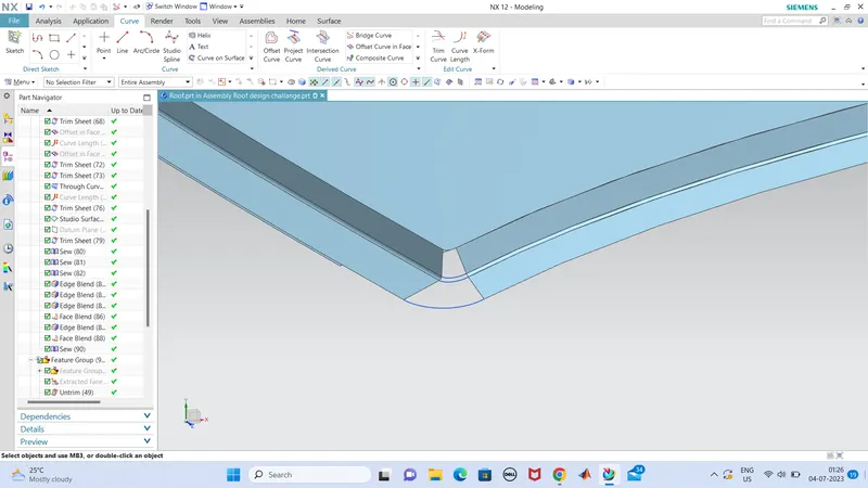
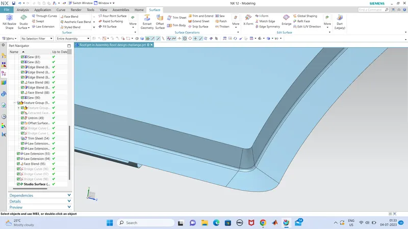
so, next we can do the rear roof rail like same process we have done in the frontal area but at a different dimensions and there is a littlebit challenging part where, the back door end opening towards inward of the rear rail roof so we should provide a clearance and of a opening curved manner.
fo that we do the same operations like extruding the face to a distance which is of a flange and extrude another surface for other flange and hence connecting these flanges at a tooling degree of 7mm and edge blended. here also a integrated part of outer panel and a inner panel. the mastix gap should be provided between these two plates and thickness is porviding last so thickness value also should be taken while making the gaps.
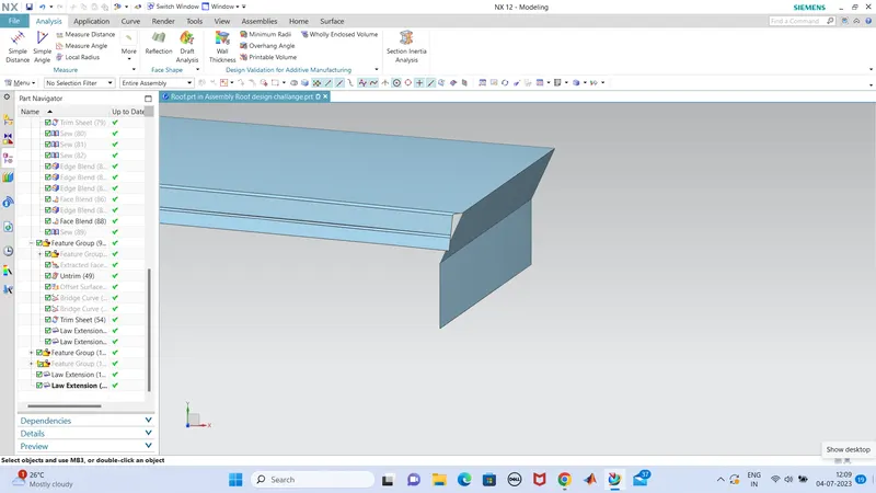
this part is curved inward,bcz while opening the back door the axis of rotation is in this inward curved area, so the clearance for the back door edge should be provided.
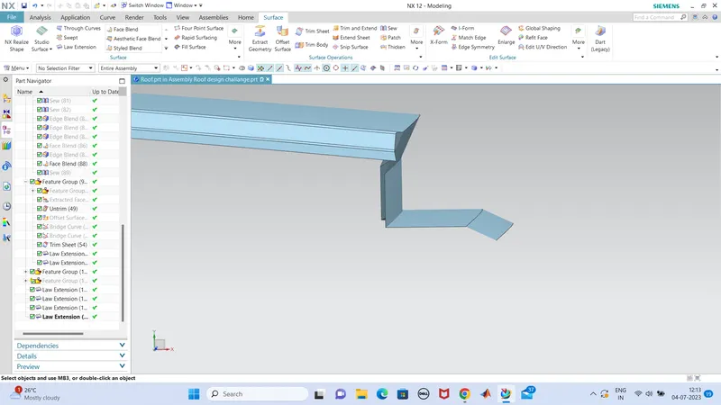
flnages are made as the given dimesions and appropriate angles.
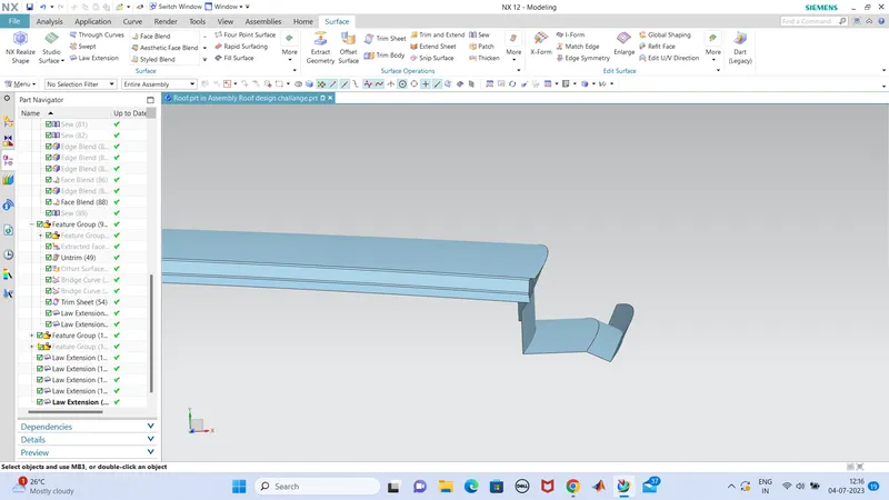
so the integrated outer roof part is done and we can done blends as well.
so now we can do the inner panel of rear roof rail. fro that offset the surfaces for each flanges and gives the proper angles which is given in the reference , so we can done it in the same way that i explained ij the part of front roof rail.
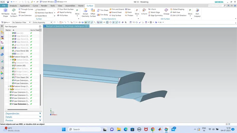
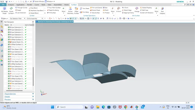
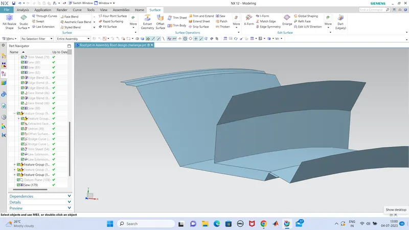
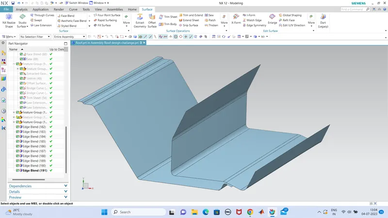
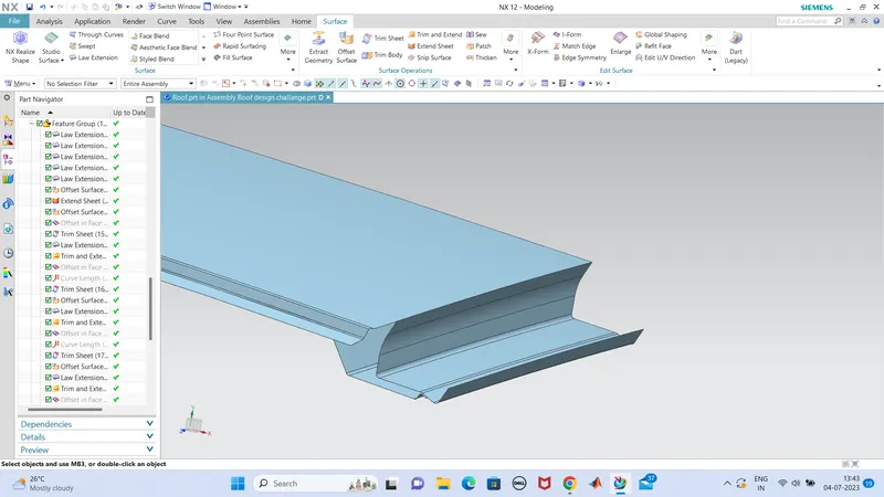
so we can see clearly that the inner and outer part that i had created with the given data.
blends can done for these parts.so the rear roof part is also done.
now we can design the bow parts, so in this roof design , a center roof part and two bow roofs are creating,bcz the roof is small to length and two bow roof is only required and these bows are providing in the flat surface of the roof part. so it gives maximum stability to the roof.
1)Center roof
the datas are given for the design of center roof part,so we calculate the dimentions which satisfy the criteria of dimentions. the center roof is of three steps of flanges wich are connected at a 7degree angle.
so we create a datum plane at a distance which the centre roof is want ro provided.(almost cente of roof).
and offset curves are made as per the flange dimentions and trimmed the each flanges and law extensions made to connect these flanges of centre roof.
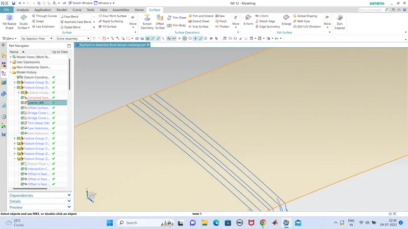
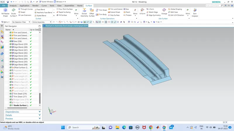
this is the centre roof part which is designed very smoothely and the edge flange is provided to ficx it with the side flangewith mastix gap.
the angle provided in these all flanges are 7degree which is the minimum tooling angle for a smoother tooling direction.
and the width is between 80mm and 90mm, we should devide those flanges appropriately.
now we can move to the bow roof which we are creating two of then in which the proess are same as that the centre roof made.
2)Bow Roof
the process is same as that we have explaine din the centre roof part.
so firstofall create a datum at adistance rom the fornt roof rail point and the width of the bow roof is about 65mm to 75 mm. we provided in between leght. so we can offste the curves at reqired lengths from the datum intersections. and offset surface are made at different offset lengths , this also have the three level of flanges and the distance between the outer roof and inner roof is provided 6.5mm (.75mm+5mm(mastix)+.75mm) and all the flange angles are 7degrees.
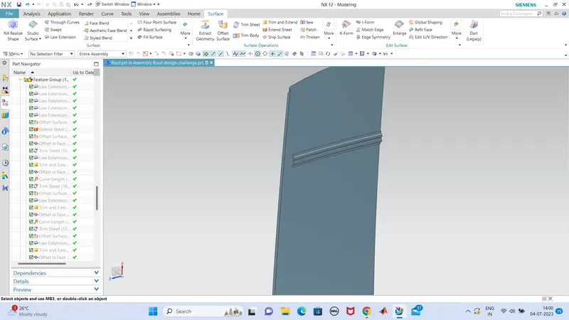
this bow roof is trimmed at the edge as done before in the center roof as well, and then form the end we provide a flange which is to connect to the side flanges and side body.
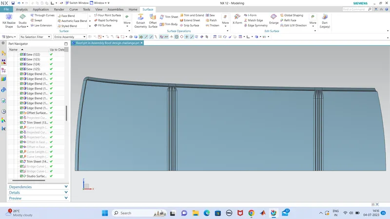
the same is the process done for the second bo roof as well.so im not explaining that again. im providing the both bows in below. the angles,width are all same but the length is small for the secong bow roof ehich is in the rear side bcz, the roof is converging slightly towards the rear end, so the bow in the rear end small in size when compared to the bow in front side. but it doesnot effect the safety feature. saftery is incresed by adding more bow roofs.
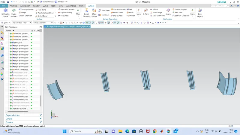
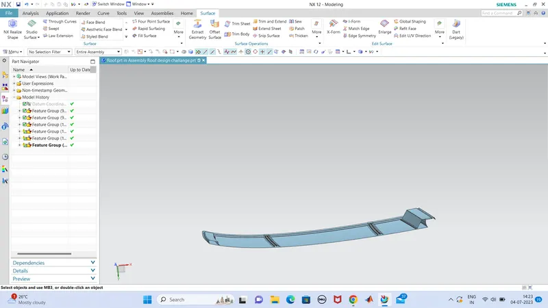
so the all parts are made, and next we can mirror the entire part with the perpendicular exis and the finished part is ready then.
i we have any issue in sewing after mirroring, we should extend the edge of each part for a small geometry and trim the whole corresponding to the
central pependicular plane so after the error would be cleared.
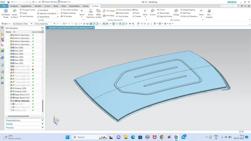
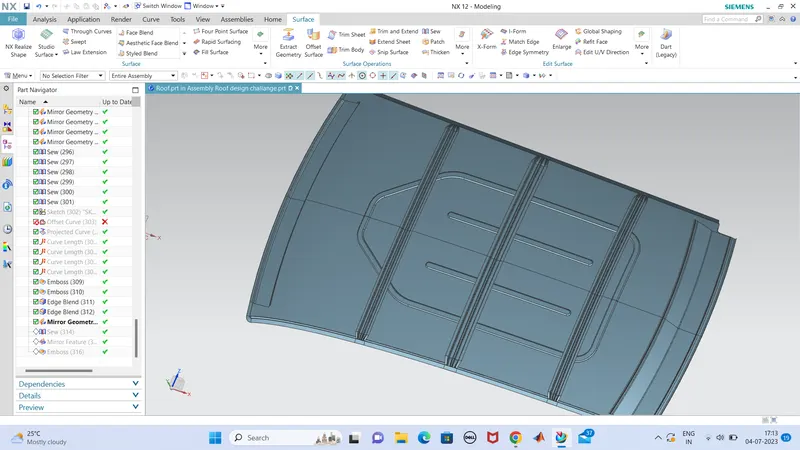
so before mirroring we can make some embosse in the roof face, so we create aketch in the roof datum plane and projected and embosse the sketch as our own design so it will gives a more strenght to the roof. and also a nice look for the vehicle from outer.the embossi created is likely aerodynamicaly in design. not so influenced by the thrust force, im only provide a 5mm of emboss projevtion outward.
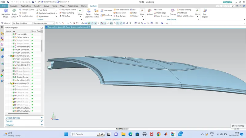
and mirrored the entire part and sewed together as a single part.
Draft Analysis
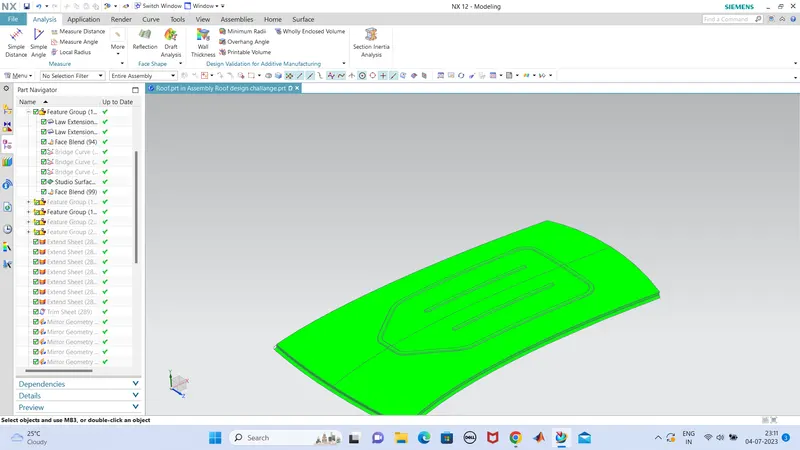
Draft analysis is done which shows part is all good.
Conclution
So the roof design challange is done with the all nececcery parts like bow roofs,center roofs all are well designed and drafted.