Roof Design
ROOF DESIGN AND ANALYSIS OF SNOW LOAD
AND HEAT DISTORTION
Objective:
To design a car roof with its component by following the master section of the front rail (front row, bow roofs, centre roof rail and rear roof rail) with all the design parameter. And also, analysis the snow load and heat distortion. Heat and snow load formulas are gives in industry standard
Master section:
Introduction:
An automobile roof or car top is the portion of an automobile that sits above the passenger compartment, protecting the vehicle occupants from sun, wind, rain, and other external elements. Because the earliest automobiles were designed in an era of horse-drawn carriages, early automobile roofs used similar materials and design
Car roof types:
- Hard top
- Sun roof
- T-top
- Targa top
- Vinyl’s top
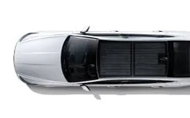
- Hardtop
Hardtop is a rigid form of automobile roof, which for modern cars is typically constructed from metal. A hardtop roof can be either fixed (i.e. not removable), detachable for separate storing or retractable within the vehicle itself.
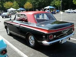
- Sunroof
Sunroof is a movable panel that opens to uncover a window in an automobile roof, allowing light and fresh air to enter the passenger compartment. Sunroofs can be manually operated or motor driven, and are available in many shapes, sizes and styles.
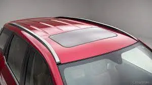
- T top
T-top (UK: T-bar) is an automobile roof with a removable panel on each side of a rigid bar running from the center of one structural bar between pillars to the center of the next structural bar. The panels of a traditional T-top are usually made of auto grade safety glass.
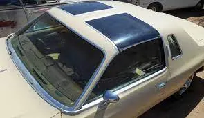
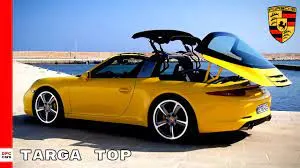
- Targa top
Targa top, or targa for short, is a semi-convertible car body style with a removable roof section and a full width roll bar behind the seats.The rear window is normally fixed, but on some targa models, it is a removable plastic foldable window, making it a convertible-type vehicle.
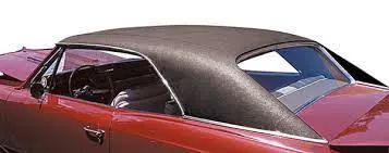
- Vinyls
Vinyl roof refers to a vinyl covering for an automobile's top.This covering was originally designed to give the appearance of a convertible to models with a fixed roof and eventually evolved into a styling statement in its own right.
Procedure:
Roof assembly the conditioner task of the roof panel is the top component shielding passenger production at connection of the body sites front and roof cross members in case of rollover component integrity is provided by the compartment frame while the roof target is only to avoid the injection of passenger providing protection against hard local contact and it’s also with stand snow load and heat distortion and also protecting wind passages. The roof is decent bye aerodynamics to pay Passing through the wind direction. Roof assembly parts are given below,
- Ditch area
- front roof rail
- rear roof rail
- bow roof rail (1&2)
- reinforcement
Roof Outer Panel:
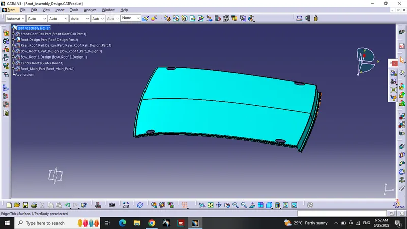
By taking the input styling surface of roof panel then first created the flanges or the ditch area at the four sides with the required open angle of 3 degree. At the front end of the roof panel, we have given the flange length of 10mm to provide the enough clearance for the windshield and its associated components like rubber sealant. The rear end also created the flanges with the required length and opening angle to allow the joining for the backdoor. Additional beads created on the top of roof panel to increase the strength of the panel. See the below image of Roof panel which is developed from the styling data.
Front Roof Rail:
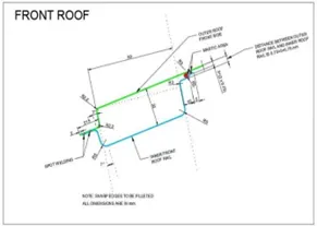
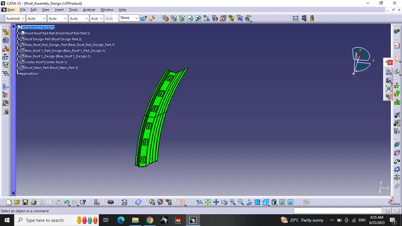
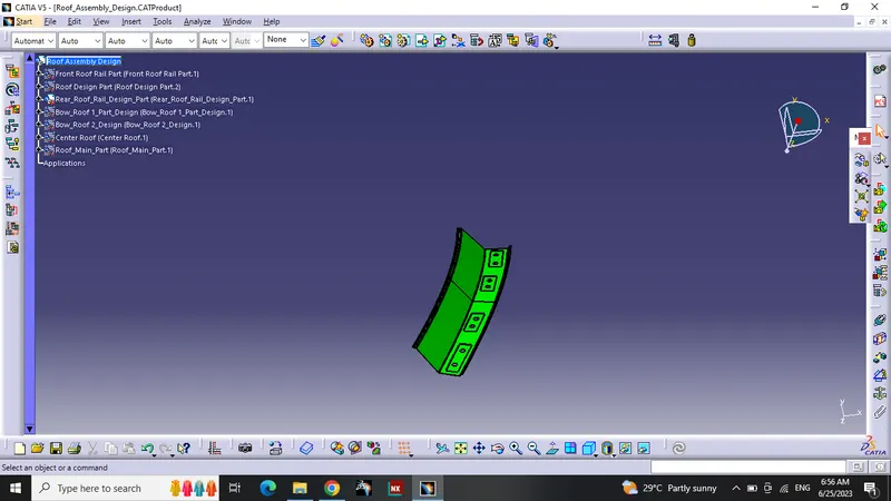
Front Roof rail is the reinforcement for the roof outer panel and as well as it joins the Roof panel with the Windshield glass and body side panel and also supports the bracket map lamp and room lamp mounting. Front roof rail created based on the master section which is developed with above mentioned functional requirements of tool opening angle, required clearance for to join with the windshield glass, visibility criteria, the deepness based on the head room clearances and the clearance mastic joining. See the below master section used for the Front Roof Rail and the Front roof rail design based on the master section.
Rear Roof Rail:
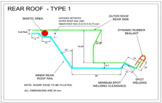
Rear Roof rail is also the reinforcement for the outer panel and it joins the backdoor and the body side outer. For designing the Rear roof rail also, we have developed a master section based on the functional requirements which are Rear visibility criteria, Rear head room clearance, Tool opening and mastic clearance. See the below image of Rear Roof rail design.
Bow Roof Rails , Front and Rear:
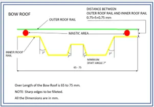
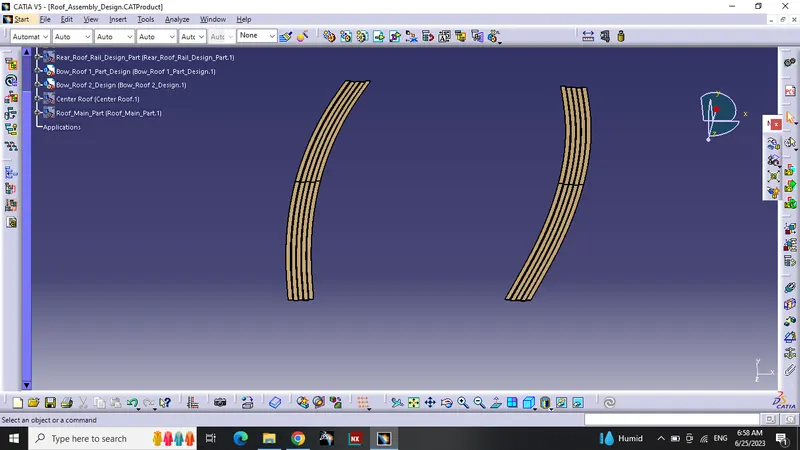
Bow Roof Rails are also the reinforcements of outer panel and are used to strengthen the roof panel and these joins to the Roof panel with the help of mastic sealant to the roof panel and connects to the body side using the spot-welding technique. These are designed based on the developed master sections developed using the criteria of Visibility and the head room clearance. And the position of these Bow roofs is mostly recommended to place at the flat portions of the Roof outer panel
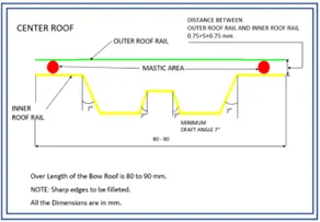
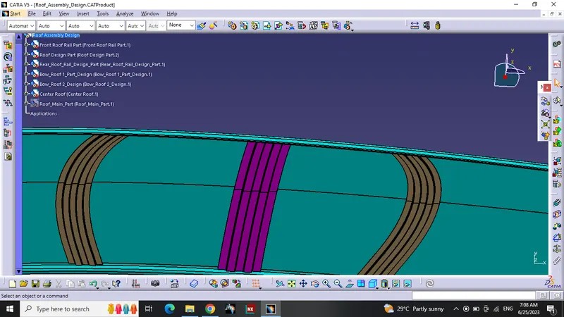
CenterRoof Rails:-Center roof rali are also rainforcement of the outer panel and are used to srenghten the roof panel and this joint to the roof panel to the help of mastic sealent to the roof panel and connect to the body using the spot welding.
Calculation:
In the assembly we’re going to calculate heat distortion criteria and snow load criteria. Heat distribution criteria is the calculation of how the roof will stand the heat capacity. And also measure the draft analysis after roof assembly. In snow load criteria we’re going to calculate snow load with stand capacity of roof. In the foreign countries in the rainy season there is a snowfall in that kind of situation roof must withstand the snow load that is why we calculate this
Heat Distortion Criteria:
Predicting heat distortion for the roof is important since it is exposed to the heat for a long time and high temperature will affect the roof structure if the designing does not confirm with the heat distortion criteria. the study helps to determine the position of roof to provide strength to the route to avoid bending and deflection of the roof due to heat. bow curvature study you see following formula will help best check whether the boardroom potion important required strength of roof.
Bow–Roof Prediction Formula,
W = [1.73 x 10^ (-3) x L] + [1.85 x 10^ (-8) x (R^2)/t] + [ 1.10x10^ (-3) x l] - 2.68
Were,
L = Roof Length in X-Direction[mm](Roof dimension in 0-Y)
R = Roof curvature
R = 2(Rx*Ry)/(Rx+Ry)
Rx = X curvature
Ry = Y curvature
t = Roof plate thickness [mm]
l = Bow Roof Span [mm]
Judgment Condition
OK< 2.7
Snow load prediction formula:
This evolution is performed in cold regions where snow a occurs. roof design must pass through the calculation to ensure that it has sufficient stiffness to withstand the load due to the accumulation of snow over the roof.
Qr = [Iyxt2] / [α x s x [(Rx + Ry)/2]2 x 10-8]
Were,
α = My x Lx2 x 10-12, My = Y(Ly-Y)
Judgement condition = Qr ≥ 3.1
250 ≤ s ≤ 380
(S varies depends on the Input)
t = Roof plate thickness [mm]
Ly= Distance between the Front and rear roof Rails on the Vehicle along 0Y [mm]
Length of Roof panel with the centre point between Roof rails Front /Rear as the reference point of the front and the rear.
Lx= Distance between the Left and Right end of the roof on the Roof BOW [mm]
Width of the roof panel exposed on the surface.
Y = Distance front Roof Rail to Roof BOW [mm]
s= Distance for which Roof BOW bears divided load [mm] s = L1/2 + L2/2
Iy = Geometrical moment of inertia of Roof BOW (Y cross section) [mm4]
Rx = Lateral direction curvature radius of roof panel Y cross section on Roof BOW [mm]
Roof panel curvature Radius of the Length Lx in Front view
Ry = Longitudinal Direction curvature radius of the Roof panel X cross section on Roof BOW [mm]
Roof panel X curvature radius of length s in Side view
Section moment of inertia:
moment of inertia, in physics, quantitative measure of the rotational inertia of a body—i.e., the opposition that the body exhibits to having its speed of rotation about an axis altered by the application of a torque (turning force). The axis may be internal or external and may or may not be fixed.
Formula
I=L/w
|
I = |
|||||
|
L = |
|||||
|
w = |
|||||
Draft analysis:
Draft analysis is the command enable you to detect if the part you draft will be easily removed. This type of analysis performs based on colour rains identification zones on the analysis element where the deviation from draft direction at any point corresponding to the specific value. This value is from both negative from positive direction. When the negative value represents good rating and positive value more than 5 will be risk high. That represent the smoothness of the part. In parts smoother more good design. In our design we going to perform this analysis to roof, front rail, rear rail, bow rails and centre rail. And check whether the roof is smoother and less in rating
Roof draft analysis:
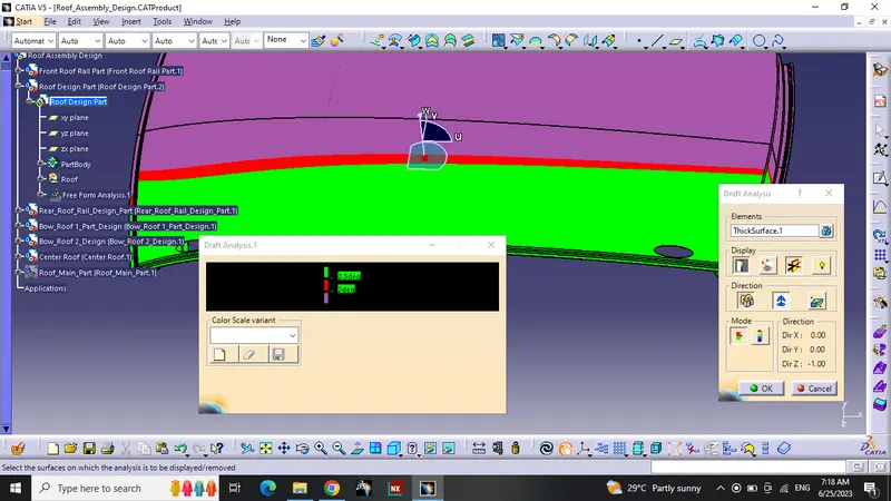
In this roof analysis most of the part showing green that mean the roof surface is smoother and it draft analysis value is less then 7.
Front and rear roof analysis:
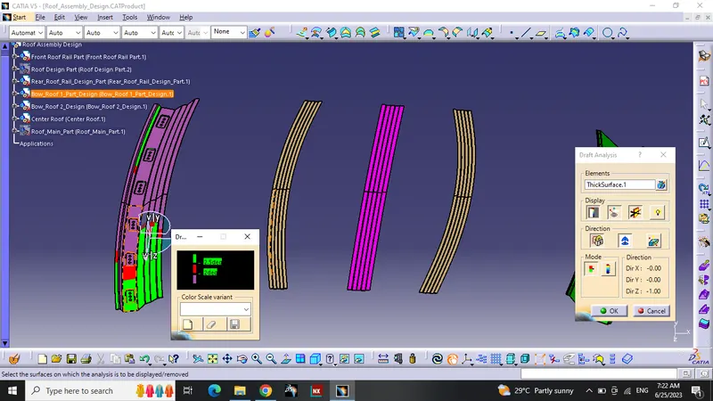
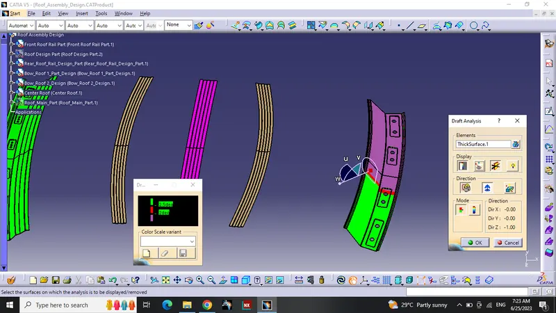
In this front and rear analysis most of the part showing green that mean the roof surface is smoother and it draft analysis value is less then 7.
Bow and centre rail:
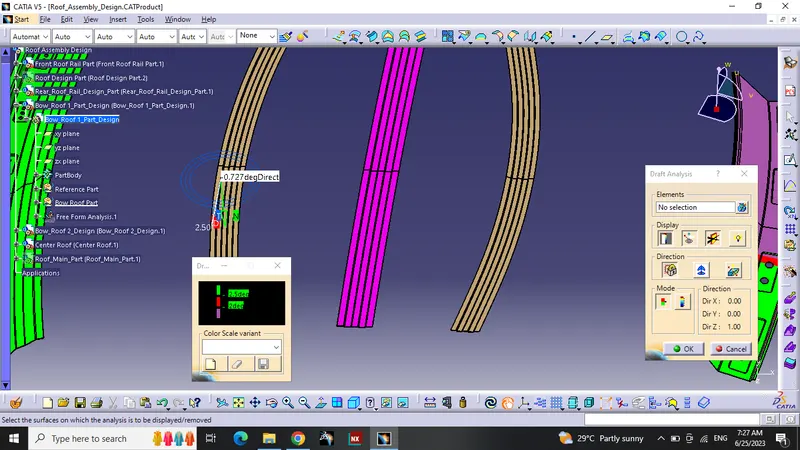
In this bow and centre rail analysis most of the part showing green that mean the roof surface is smoother and it draft analysis value is less then 7.
CONCLUSION:
Hence finally the roof design and analysis of the snow load and heat distortion complete. In the heat distortion calculated and part are pass the industry standard. In the snow load calculation are done and there is only one part not pass the stand. This project was done by Catia V5 software.