Roof Design
Roof Design:
What is roof of a car?
Roof of a car is an important element in a car from different aspects. It plays an important role in passenger safety. It protects the passenger from different external agents like dust, debris, high velocity stream of air, water, etc. It is also an important structural element of a car. It is designed in such a way that it can resist different types of loading, most importantly compressive and bending loads. The roof is supported by the car’s other structural elements such as A pillar, B pillar and C and/or D pillar. The systematic assembly of these elements reduces the risk of life to the passenger by great extent during a situation of crash.
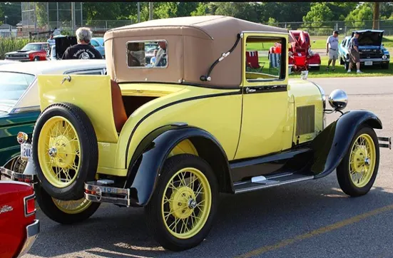
In the 1900s to 1920s cars didn’t used to have roofs. Most of the cars used to have a roof made of fabric or vinyl. In the 1970s, popularity of these roof began to fall, because of 3 reasons, safety, security and faster pace of life. In 1970 the National Highway Traffic Safety Administration issued a regulation for the roofs as there were cases of varying degree of roof crumpling in 25% of the rollover accidents.
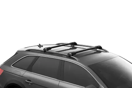

Components in a roof:
A car roof is a complex assembly of different element helping it achieve the safety requirements established by various automotive regulatory bodies around the world. Roof consists of structural members such as:
- Outer roof panel
- Front roof rail
- Rear roof rail
- Centre roof reinforcement
- Bow roof rails
These components add to the structural safety of the car in a situation of impact from above. They are arranged in a form of ladder which helps in reducing the deflection in the roof outer panel hence reducing the bending loads.
Outer roof panel:
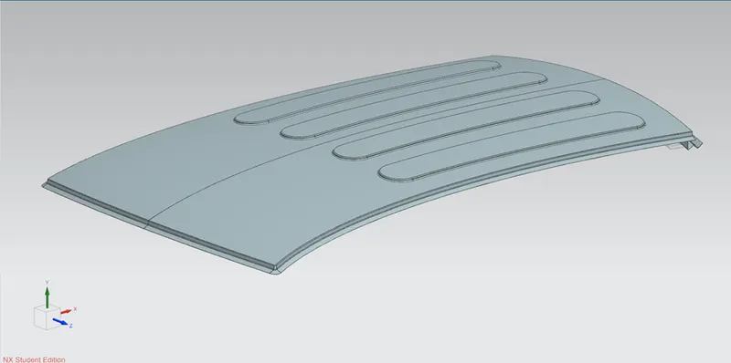
- The outer roof panel is the outer surface of the car. It is the member which first comes in the contact with the load in case of a rollover crash.
- It is made up of same automotive sheet metal which is used in BiW of the rest of the car.
- The front and the rear of the panel consists of flanges of around 21mm as per the master-section provided.
- It is used to mount other car parts like car’s windshield and rear glass panel.
- It is used to perform spot welding to join the front roof rail and rear roof rail.
- The flange runs around the front and the side part of the car. To join the front and the side flange, we need to trim the corners using bridge curve and use studio curve by creating guide curves.
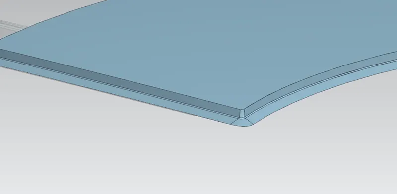
- There is a discontinuity in the flange at the rear for mounting of the C or D pillar and covering the gap.
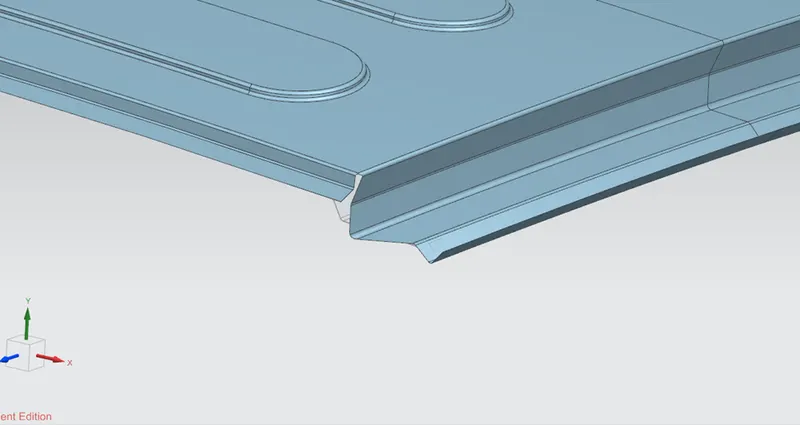
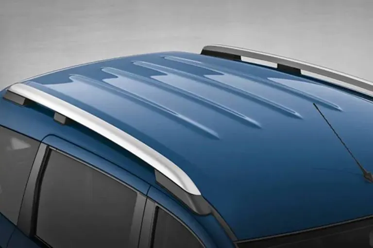
- Embosses are created on the top to enhance the strength of the panel.
Front roof rail:
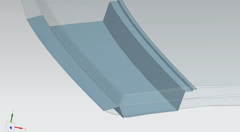
- The front roof rail is a structure which is used to join the roof outer panel and the car’s A pillar. The width of it is larger than other structural members other than the rear roof rail.
- While designing we should keep in mind the visibility criteria from front such that it doesn’t hinder the view of the driver. Also, we need to give enough clearance for the inner roof line.

- The flanges and the base surface must be created as shown below using offset surface and through curve commands and trimming it to the length specified in the master-section.
Design process:
- First, we have to copy the outer surface using wave geometry linker and offset the outer panel to 32 mm downwards.
- Using a datum plane, offset it to 80 mm. Use intersection curve draw a line passing through the plane on the outer panel.
- Offset the curve using through point and trim the offset surface by projecting the offset curve on the offset surface using vector direction.
- Following the above steps create the other flanges of 10 mm and 5 mm width respectively. Using through curve, join the edges with position continuity.
- Before adding fillets, extend the sheet on the side which is going to be mirrored then trim it with the x-y plane. Sew all the edges and perform edge fillet with given radius.
- To add strength to the component, use dart at sufficient gap intervals. Use embosses to further increase the strength of the flat portion of the rail.
Rear roof rail:
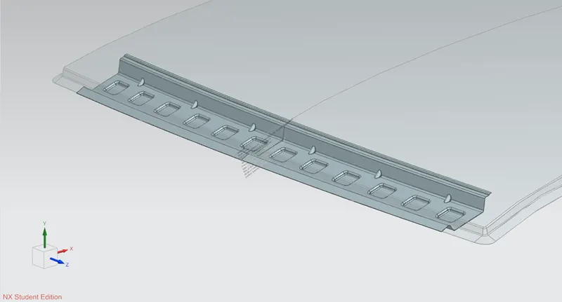
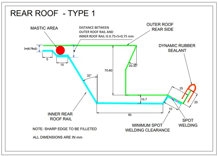
- The rear roof rail is a structure which is used to join the roof outer panel and the car’s C and/or D pillar. The width of it is larger than other structural members.
- Similar to the front roof rail, we have to create the basic structure of the rear roof rail as per the master-section given.
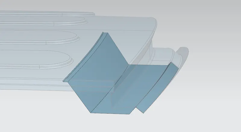
Design process:
- Similar to the front roof rail, we have to offset the outer surface to 90.7 mm. Then the other 2 surfaces to 6.5 and 4.5 mm respectively.
- Calculate the individual width of the flange if the drafting angle is 32o. accordingly perform the offset curve and trim the offset sheets. Join them using through curve with position continuity.
- Extend the sheets and trim them with x-y plane for proper mirroring. Sew them all and apply edge fillets according to the master-section.
- Mirror them with x-y plane. Use darts at sufficient gaps and add embosses to increase the strength.
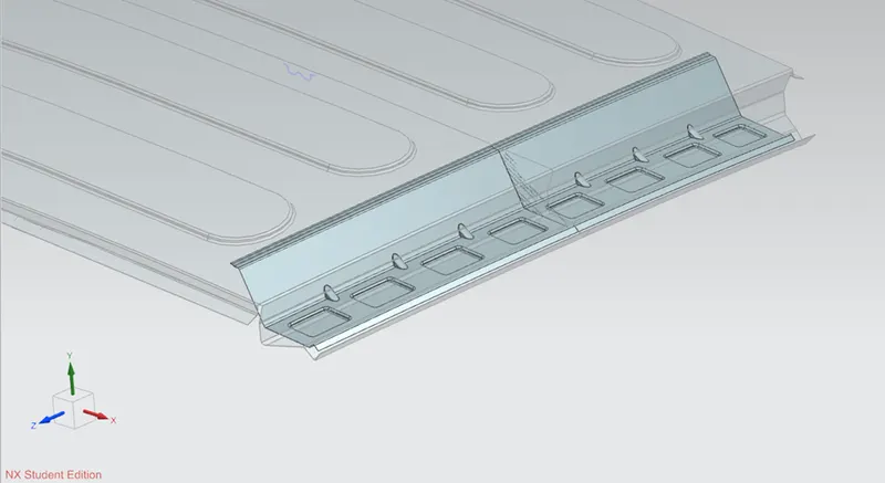
Centre roof reinforcement:
- The centre roof reinforcement (centre roof rail), as the name suggests that it is located at the middle of the roof, almost at half the length of the roof along the x axis.
- It is one of the main load bearing elements of the roof. Thus, the width of it is larger than the other bow roofs in the assembly.
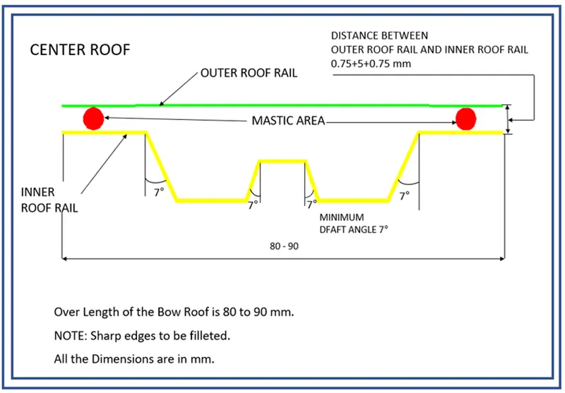
Design process:
- Here, we have to offset the outer surface in 3 levels. 1st surface at 6.5 mm. The subsequent surfaces offset at 5 mm from each other. Trim each sheet at the given distance. Make sure that the overall width lies within 90 mm.
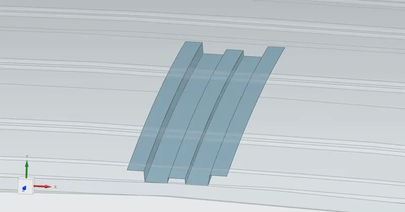
- Extend and trim the sheet for proper mirroring of the sheet. Then apply edge blend with appropriate radius and use mirror geometry to mirror component and sew them.
- Using wave geometry linker extract the side flange and trim it such that it has at least 20-30 mm gap between the edges of each of the flange. Trim the sheet.
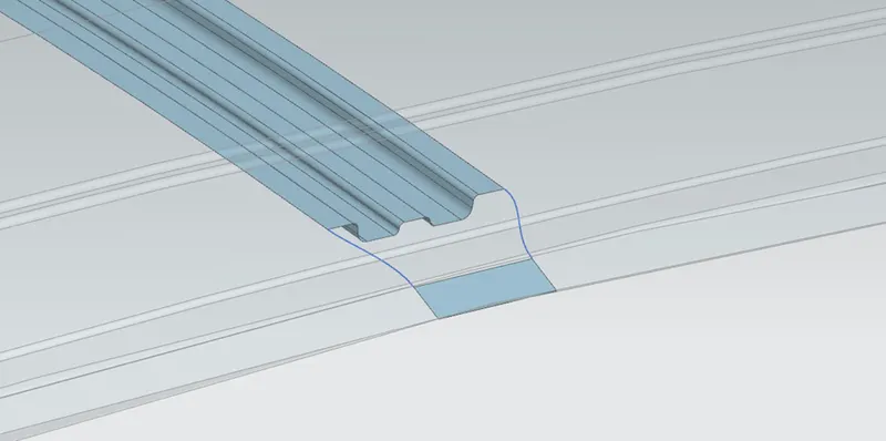
- Using through curve mesh, join both sheets with tangent continuity. Using bridge curves on the flange trim off the sharp edges with appropriate radius.
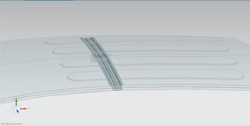
Bow roof rail:
- Bow roof rails provide support to the roof outer panel between the centre roof reinforcement and the end roof rails (front and rear).
- The width of the bow roof is less than that of centre roof reinforcement. But, the shape of the cross-section remains the same.
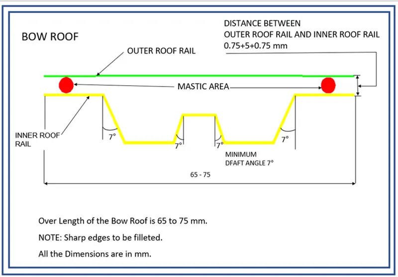
- The design process remains the same as that of the centre reinforcement rail. The main difference lies in the width. It must not exceed 75 mm.
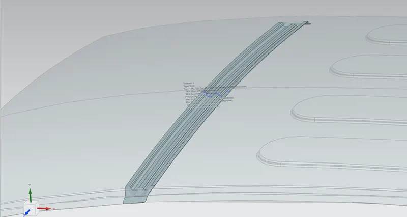
Roof crush test:
It is one of the important carried out to test the strength of the roof. It is also called as rollover test. This test is conducted according to the guidelines prescribed by Institute of Highway Safety. These rules came into being after analysing a number of different crashes occurred on highways.
In this test roof undergoes loading on the roof and then load is removed and checked if the roof regains its shape and how long does it take. Also, the roof is crushed as shown below and checked the health of the dummy inside the car. The standards are mentioned in the figure below.
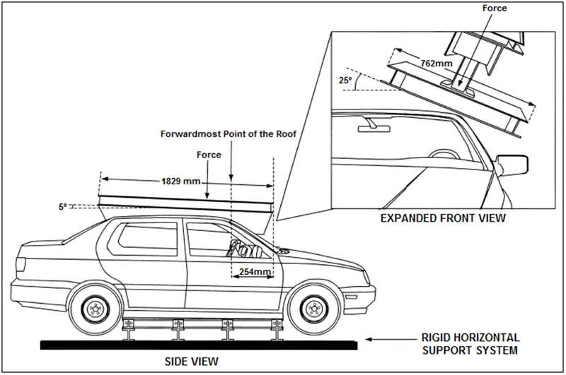
The load applied should displace the assembly not greater than 127 mm when a load of 1.5 times the empty vehicle or 22,240 N whichever is smaller is applied. This test is conducted for 120 s at crushing speed of 13 mm/s.
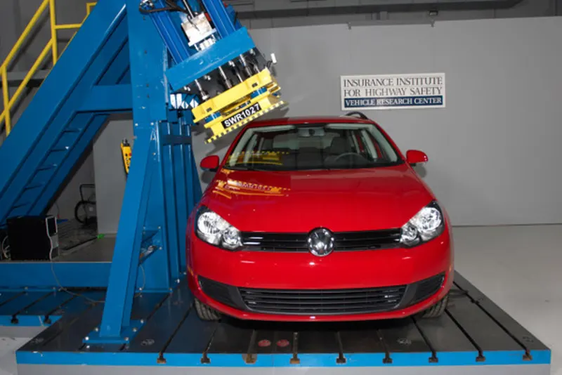
Conditions:
- The doors and windows of the vehicle should be closed.
- The vehicle must be empty from inside, except the dummy.
After the conduction of the rollover test, load vs displacement graph is plotted. A safe line is drawn, above which the vehicle roof is considered to be safe.
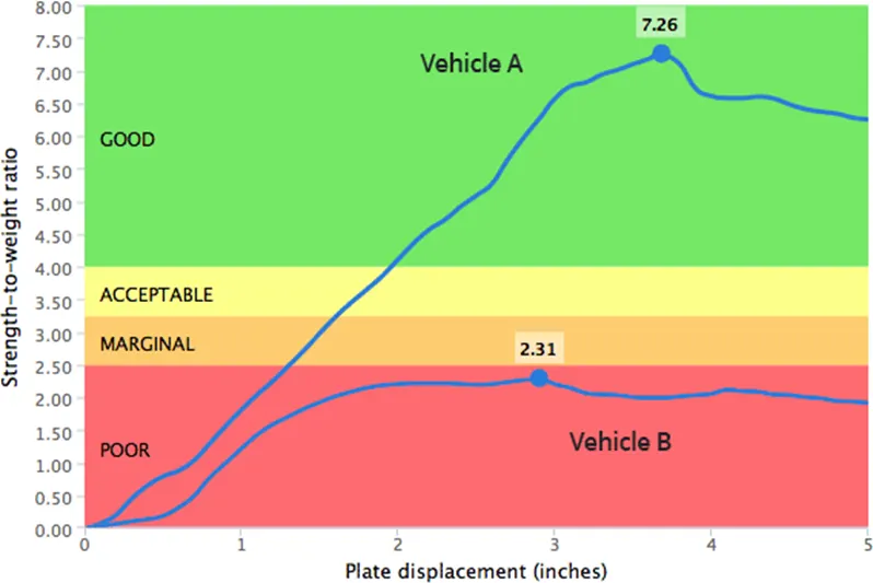
While designing the roof, it must satisfy a few geometrical conditions. It will further help in reduction of impact and deflection when these tests are conducted. These conditions are:
- Heat distortion condition
- Snow load condition
Heat distortion condition:
- Car’s roof is highly susceptible to higher temperature as they are the first members to come in contact with sun’s heat. Upon heating, the metal tends to deform due to thermal expansion when applied with a specific load.
- High tensile steel sheets are used in manufacturing of car bodies. It is used in order to improve the vehicle performance and reduce its fuel consumption.
- They are thinner than the conventional sheet metal. It is used to make roof outer panel, door panels, etc. It makes the car body lighter and its performance better.
- It comes with its own limitations. These panels showed the tendency to bend due to thermal stress during the processes of painting drying.
- It happens when body is put through the drying process after electrocoating. When thermal distortion happens, it requires reworking and a lot of checks. This can take up a lot of labour time.
Surface formation and calculation:
- First, we have to draw a sketch on z-x plane. Before that, make sure that the necessary faces are extracted.
- Draw a line 300 mm away from parallel to the x axis. This is called as 3Y line. Offset this line at 100 mm in both side of the 3Y line.
- Project the ends of the extracted faces. Create a mid-point in between the edges of front roof rail and its adjacent bow roof rail. Repeat this process with bow roof 1 – centre reinforcement rail, centre reinforcement rail – bow roof 2 and bow roof 2 – rear roof rail.
- Draw a line in y direction through those mid-points. Offset these lines for 100 mm in both directions. You get a grid like structure as shown below:
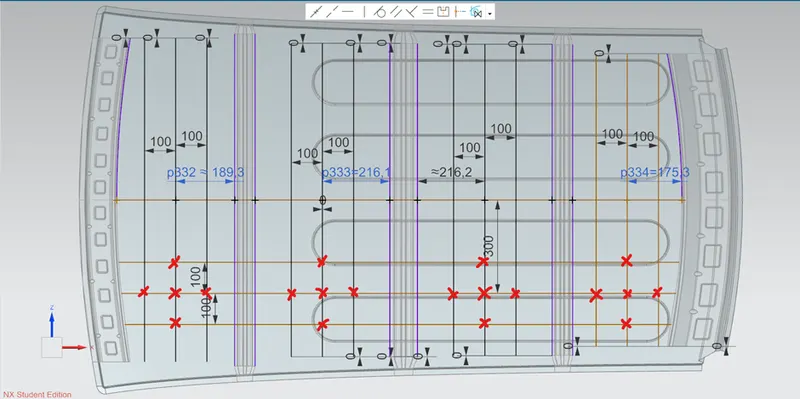
- Project these curves on the outer panel and create points on the red cross using point at intersection of 2 curves.
- Draw 3-point arcs joining as shown. Calculate the radius using local radius analysis and tabulate. The longitudinal arcs are Ry with respect to y axis and the lateral ones are Rx.
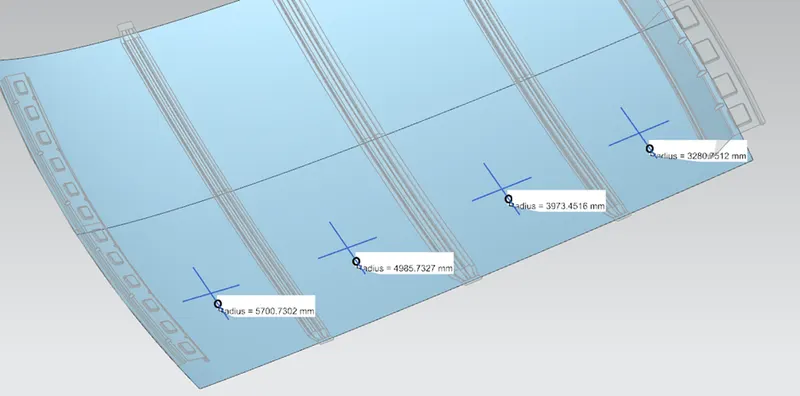
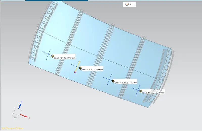
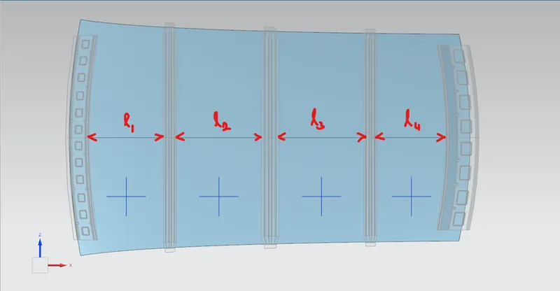
- The Bow roof span is determined as follows:
The heat distortion condition is calculated using the following relation:
W = [1.73L x 10-3] + [1.85 x 10⁻⁸ x (R2/t)] + [1.1 x 10⁻³ x l] – 2.68
Where,
L = Roof length along x axis i.e., 0Y line
R = Roof curvature
= [2 x (Rx x Ry)] / (Rx + Ry)
Rx = Curvature along x axis
Ry = Curvature along y axis
t = Roof plate thickness.
l = Bow roof span.
Upon calculating, we get the following data:
|
section |
Rx (mm) |
Ry (mm) |
N = Rx X Ry |
D = Rx + Ry |
R=2 X N/D |
L (mm) |
l (mm) |
t (mm) |
W |
result |
|
FRR |
2525.31 |
5700.73 |
14396110.48 |
8226.04 |
3500.13141 |
2039 |
304.241 |
0.75 |
1.484 |
ok |
|
BRR 1 |
6202.121 |
4985.732 |
30922113.14 |
11187.853 |
5527.80111 |
2039 |
432.711 |
0.75 |
2.076 |
ok |
|
CRR |
10662.354 |
3973.452 |
42366351.83 |
14635.806 |
5789.41151 |
2039 |
432.23 |
0.75 |
2.148 |
ok |
|
BRR 2 |
14027.021 |
3280.751 |
46019163.17 |
17307.772 |
5317.74548 |
2039 |
337.7 |
0.75 |
1.915 |
ok |
Snow load condition:
- This criterion holds importance in the non-tropical parts of the world like Europe, Canada, Russia, etc., where average temperature falls below 0oC in the winters. Due to this, in the months of December and January snowfall is a daily affair.
- Thus, due to snowfall the roof accumulates a lot of snow which can weigh up to 500kgs. This has the ability to deform the roof.
- Snow load condition checks if the roof has the ability to regain its shape once the load (snow) is removed.
- The roof must be designed in such a way that the roof can have sufficient stiffness so that it can withstand the load on the roof.
- This criterion can also help in deciding the weight of the cargo which can be kept on the roof.
Surface formation and calculation:
- Similar to the heat distortion condition, we need to create a sketch on x-y plane. Draw a line which is coincident with the y axis. This is the 0Y line.
- Offset this line for 100 mm on both sides. Project all the edges of the roof rails. Create mid points with respect to these lines’ end points on the y axis.
- Similar to the heat distortion condition, draw lines perpendicular to y axis such that it passes through the mid-points between each of the adjacent rails.
- Offset these lines for 100 mm on both sides. You will obtain a grid structure shown below. Project these curves on the outer panel.
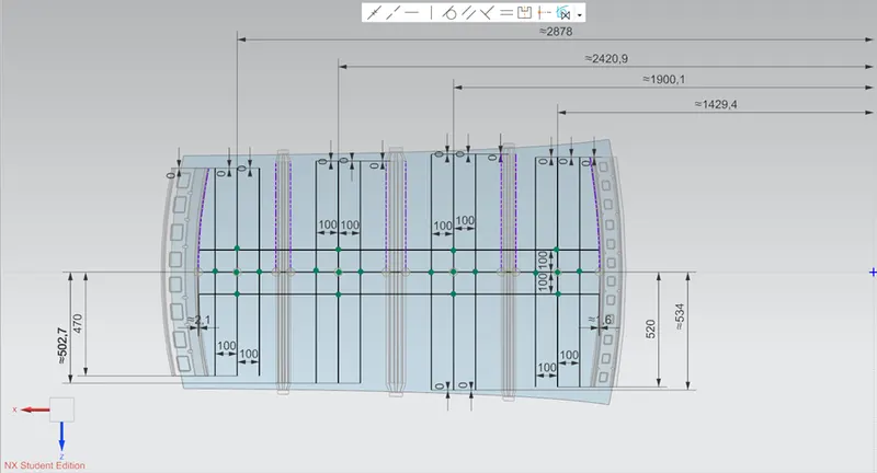
- Project these curves on the outer panel and create points on the red cross using point at intersection of 2 curves.
- Draw 3-point arcs joining as shown. Calculate the radius using local radius analysis and tabulate. The longitudinal arcs are Ry with respect to y axis and the lateral ones are Rx.
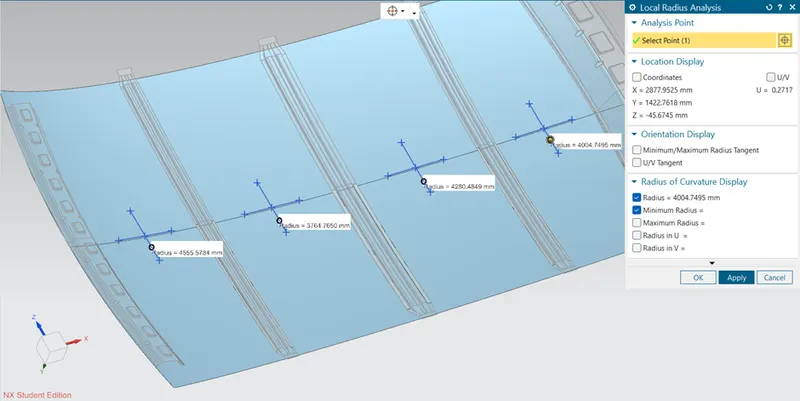
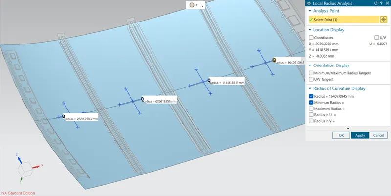
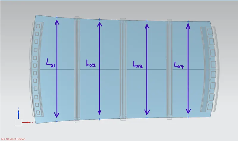
- Project the side curves of the roof. Use the mid points we created on the surface for the calculation of the arc. Draw lines perpendicular to y axis passing through the mid points, whose end points lie within the side curves.
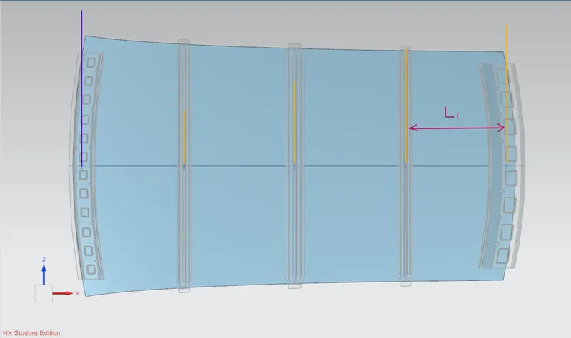
- Mark the points and project them on the outer panel. Measure the distance between their respective opposite points. It will be the Lx for each case.
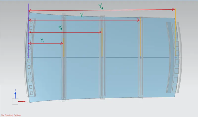
- Determine mid points of each roof rail along its width. Measure the distance of each mid-point with respect to the mid-point on the front roof rail. It gives the value of Y for each case.
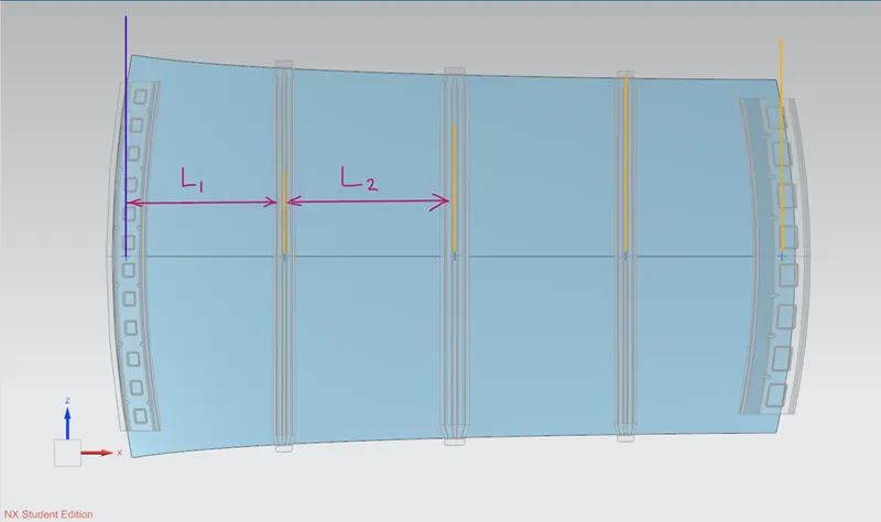
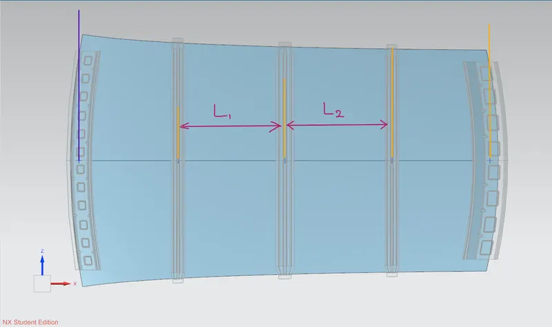
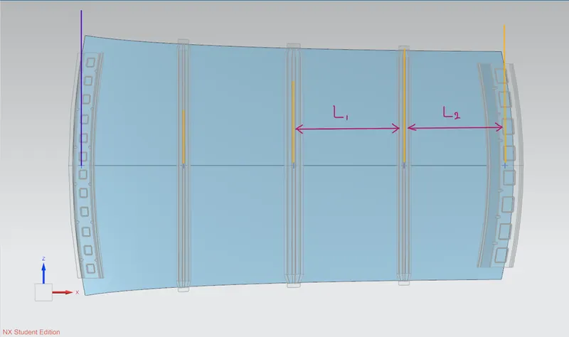
- L1 and L2 for each case:
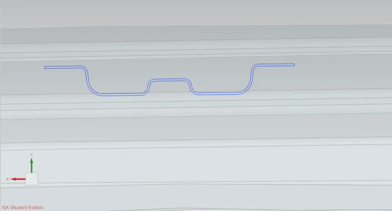
- To calculate the moment of inertia, we need a closed cross section of the member. To obtain it, use intersection curve and use inputs as the thickened part and the x-y plane.
- In the similar plane, project the intersection curve and finish the sketch. Use the section inertia analysis to obtain data on the cross section.
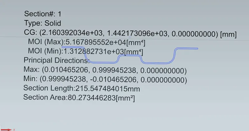
- Use the minimum moment of inertia for the calculation.
The snow load condition is calculated using the following relation:
Qr = [Iy x t2] / [α x s x [(Rx + Ry) / 2]2 x 10⁻⁸] and α = My x Lx2 x 10-12
where, My = Y x (Ly - Y)
t = roof plate thickness (mm)
Ly = Distance between the front and rear roof rails along y axis (mm)
Lx = Distance between the left and right end of the roof outer panel (mm)
Y = Distance of front roof rail from the bow (mm)
s = Distance for which the bow roof bears the divided load (mm)
= (L1 / 2) + (L2 / 2)
Iy = Geometric moment of inertia of the element (mm4)
Rx = Curvature along x axis
Ry = Curvature along y axis
Upon calculating, we get the following data:
|
SECTION BETWEEN |
Iy |
Lx |
Ly |
L1 |
L2 |
Rx |
Ry |
|||||||
|
FRR - BRR1 |
931.74 |
1148.603 |
1970.378 |
477.438 |
509.306 |
2588.28 |
4555.578 |
|||||||
|
BRR1 - CRR |
1312.882 |
1097.52 |
1970.378 |
509.306 |
509.783 |
6097.955 |
3764.765 |
|||||||
|
CRR - BRR2 |
966.882 |
1068.71 |
1970.378 |
509.783 |
468.51 |
11145.551 |
4280.484 |
|||||||
|
BRR2 - RRR |
(-) |
1054.768 |
1970.378 |
468.51 |
0 |
16407.094 |
4004.75 |
|||||||
|
t |
Y |
s |
My |
[(Rx+Ry)/2]^2 |
α |
Qr |
||||||||
|
0.75 |
477.438 |
493.372 |
712786.3 |
12758676.78 |
0.940371 |
8.853967105 |
||||||||
|
0.75 |
984.6 |
509.5445 |
970597 |
24318311.45 |
1.169133 |
5.097636305 |
||||||||
|
0.75 |
1491.683 |
489.1465 |
714061.2 |
59490638.96 |
0.815559 |
2.291676126 |
||||||||
|
0.75 |
1957.629 |
234.255 |
24957.81 |
104160843.9 |
0.027766 |
0 |
||||||||
Draft analysis of each part:
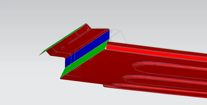
Roof outer panel:
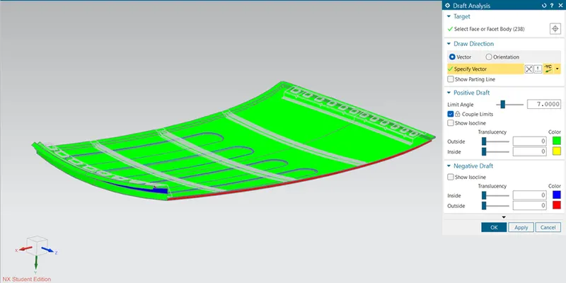
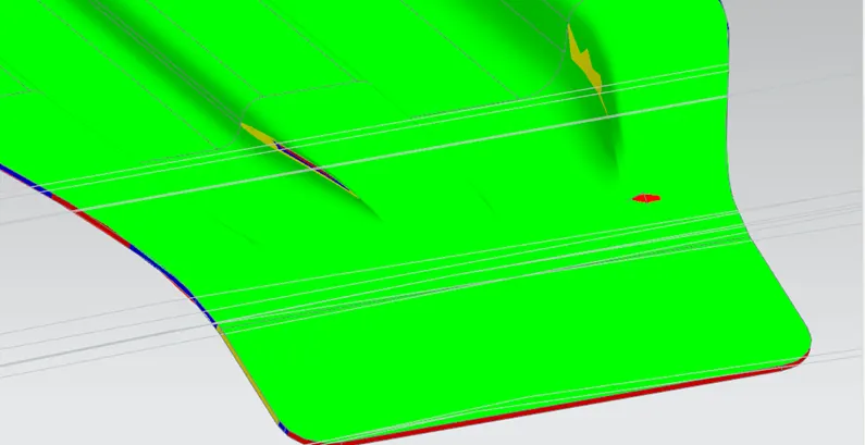
Roof outer’s 90% sheet can be tooled. But the rear part, where the rear roof rail is to be mounted is difficult to tool. Hence it needs some special mechanism to tool it out.
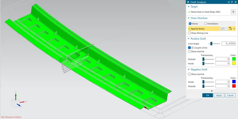
Front roof rail:
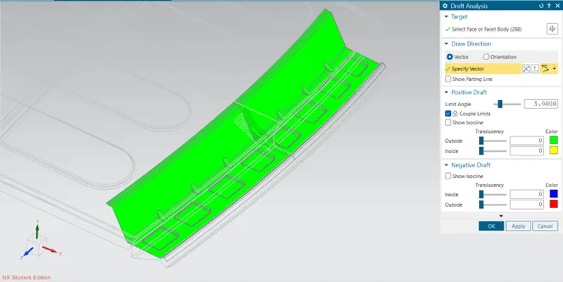
Rear roof rail:
Centre reinforcement rail:
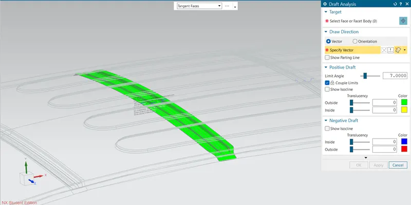
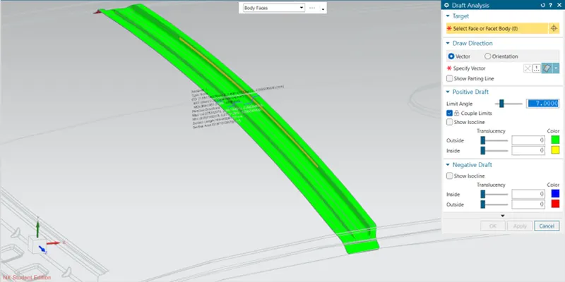
At certain parts, due to improper surface generation, we have 0o draft which might create hurdle to tool the part out.
Bow roof rail:
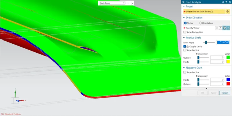
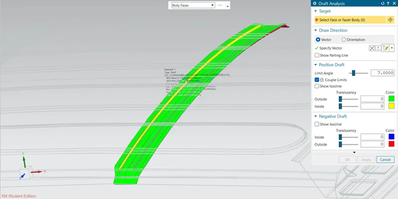
Same is the condition with other bow roof rails.
Bow roof 2:
Conclusion:
To pass the heat distortion condition, W < 2.7 and to pass the snow load condition, Q > 3.1. Failing to meet these requirements symbolise that the roof doesn’t has adequate strength to withstand thermal and physical load and hence may lead to permanent deformation.
From the above data we can see that the roof, however qualifies the heat distortion condition, but fails to qualify the snow load condition. Thus, it is suitable for tropical regions but cannot cater to the non-tropical regions. To increase the strength of the roof outer panel, create large embosses on it. It increases the rigidity of the roof outer panel. It not only helps in improving in structural properties, but sometimes also help in improvement in aerodynamic performance of the car.
Documents attached:
Part files.zip
images.zip
Roof Design.docx