Roof Design
The roof of a car is an integral part of its overall structure, providing protection, support, and aerodynamic performance. It serves as a protective barrier against external elements such as rain, sun, wind, and debris. The design and construction of car roofs vary depending on the type and purpose of the vehicle, ranging from sedans and SUVs to sports cars and convertibles.
Materials: Car roofs are typically made from various materials, including steel, aluminum, carbon fiber, or composite materials. The choice of material depends on factors such as cost, weight, structural integrity, and manufacturing capabilities. Steel is commonly used for its strength and affordability, while aluminum offers a lightweight alternative that can enhance fuel efficiency. Carbon fiber and composite materials are utilized in high-performance vehicles to reduce weight and increase rigidity, but they are more expensive.
Materials: Car roofs are typically made from various materials, including steel, aluminum, carbon fiber, or composite materials. The choice of material depends on factors such as cost, weight, structural integrity, and manufacturing capabilities. Steel is commonly used for its strength and affordability, while aluminum offers a lightweight alternative that can enhance fuel efficiency. Carbon fiber and composite materials are utilized in high-performance vehicles to reduce weight and increase rigidity, but they are more expensive.
Types of Roofs:
-
Hardtop Roof: Most conventional cars have a hardtop roof, which consists of a solid, fixed structure that covers the passenger compartment entirely. This type of roof provides maximum protection, insulation, and structural integrity. Hardtop roofs can be either fixed or retractable (in the case of sunroofs), allowing for ventilation and natural light.
-
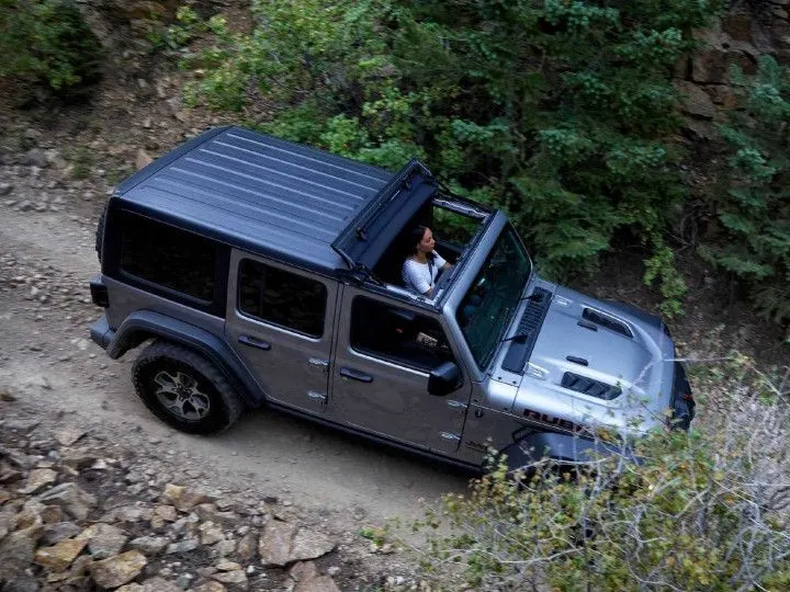
Soft-top Roof: Soft-top roofs are commonly found in convertible cars. They are made of flexible materials like vinyl, canvas, or cloth, and can be folded or retracted to expose the passenger compartment to open air. Soft-top roofs provide an open-air driving experience and can be manually or electronically operated. They typically feature additional reinforcement to maintain structural integrity when the roof is up.
-
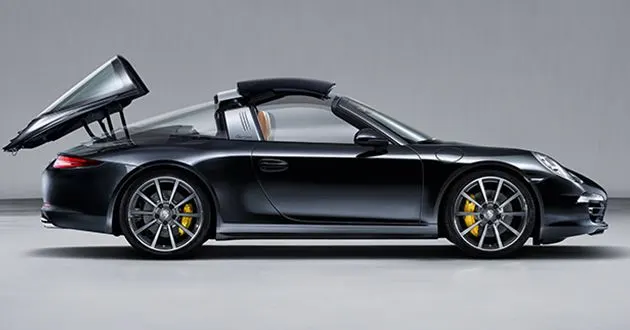
Targa Roof: The targa roof is a hybrid design that combines elements of both hardtop and convertible roofs. It consists of a removable or retractable panel above the front seats, allowing for an open-air experience while maintaining a fixed rear section. Targa roofs are commonly found in sports cars, offering a compromise between the security of a hardtop and the exhilaration of a convertible.
-
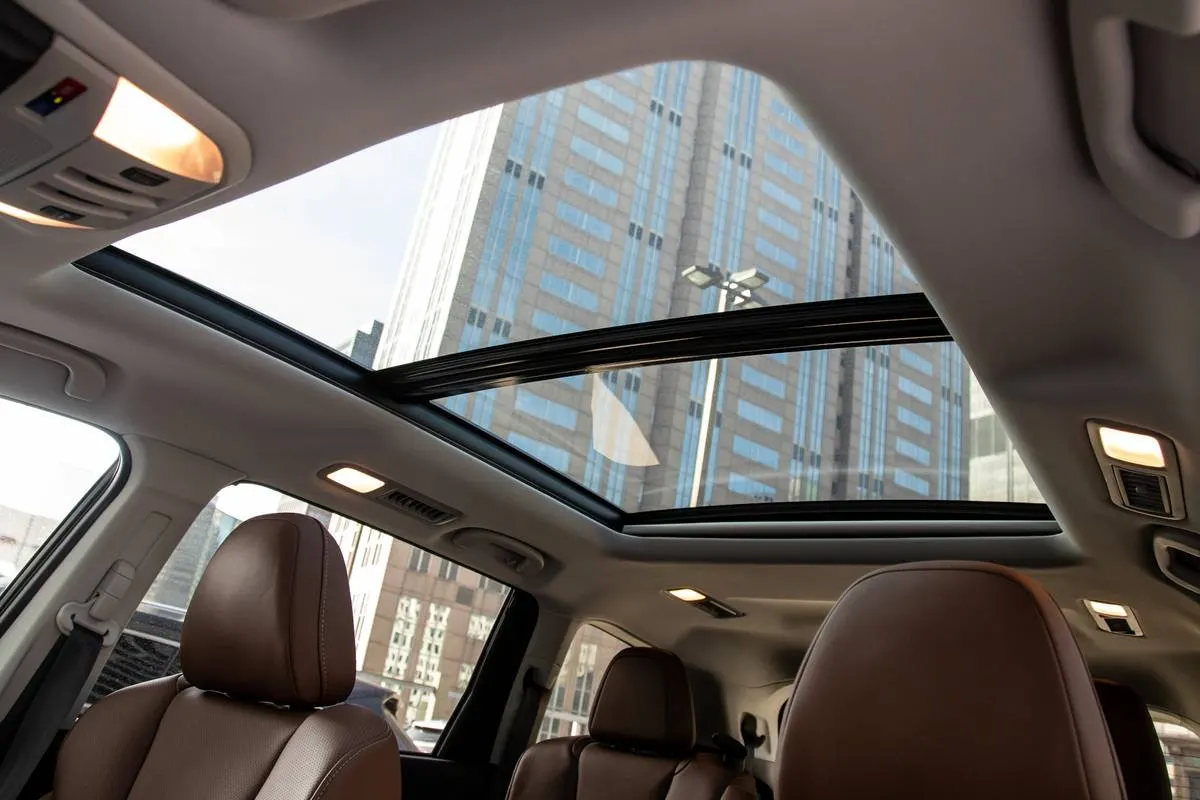
Panoramic Roof: Panoramic roofs are a relatively recent addition to car designs. They are large glass panels that cover a significant portion of the roof, extending from the front windshield to the rear window. Panoramic roofs provide an expansive view of the sky, increasing the sense of space and openness inside the car. They can be fixed or feature a sliding or tilting mechanism for ventilation.
Manufacturing:
Car roof manufacturing involves the production of sheet metal components using various processes such as forming, drawing, trimming, and more. These processes are crucial in shaping and assembling the roof structure of a car. Let's explore each step in more detail:
-
Material Selection: Car roofs are commonly made of sheet metal, such as steel or aluminum. The choice of material depends on factors like cost, weight, strength, and design requirements.
-
Sheet Metal Forming: Forming is the initial step where the flat sheet metal is shaped into a three-dimensional structure resembling the roof. There are different techniques used in forming, including:
-
Stamping: Stamping involves pressing the sheet metal against a die using a stamping press. The die has the desired shape of the roof, and the force applied by the press helps deform the metal into the required shape.
-
Hydroforming: In hydroforming, the sheet metal is placed in a die and subjected to high-pressure fluid, typically water or oil. The pressure forces the metal to conform to the shape of the die.
-
Roll Forming: Roll forming is a continuous process where the sheet metal passes through a series of rollers to gradually shape it into the desired profile.
-
-
Drawing: Drawing is a forming process used to create deeper and more complex features, such as recesses or flanges, on the sheet metal. It involves pulling the sheet metal into a die cavity using a punch. Drawing can be performed in multiple stages to achieve the desired shape.
-
Trimming: After the forming and drawing processes, the excess material or flash around the edges of the roof component needs to be removed. Trimming involves cutting or shearing the sheet metal to its final size and shape.
-
Bending and Folding: Bending and folding processes are employed to create specific angles, curves, or folds in the sheet metal. These techniques help shape the roof component precisely according to design specifications.
-
Joining: Once the individual roof components are formed, they need to be joined together. Various joining methods can be employed, including welding, adhesive bonding, riveting, or clinching, depending on the material and design requirements.
Design Methodology:
- Understanding the input class-A skin data and the corresponding master section data
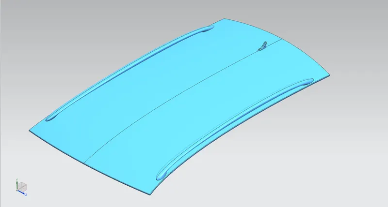
- Once the input data is imported into the workbench, it is important to use them as reference surfaces rather than consuming them in boolean operations. For this case, extract geometry & offset surface with 0mm offset can be utilized to make copies for the working surface. This eases utilizing parent surfaces down the deisgning path whenever required.
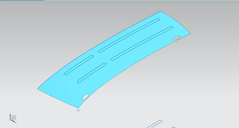
- Based on the master section. the flange on the outer panel is developed w.r.t the fron rail roof as well as the side flanges.
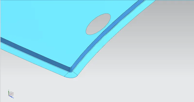
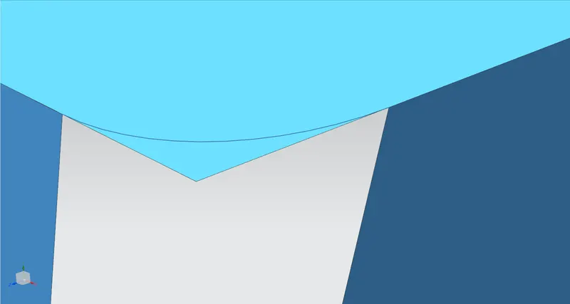
- In general, all sharp corners have to be made smooth aiding in stress concentration elimination
Front Rail Roof:
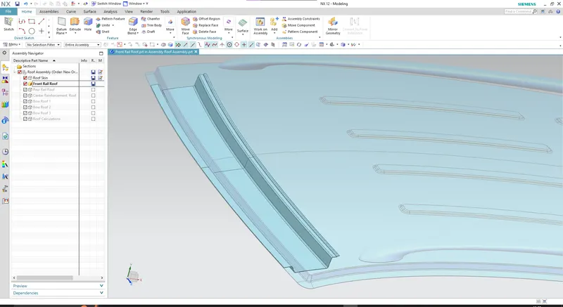
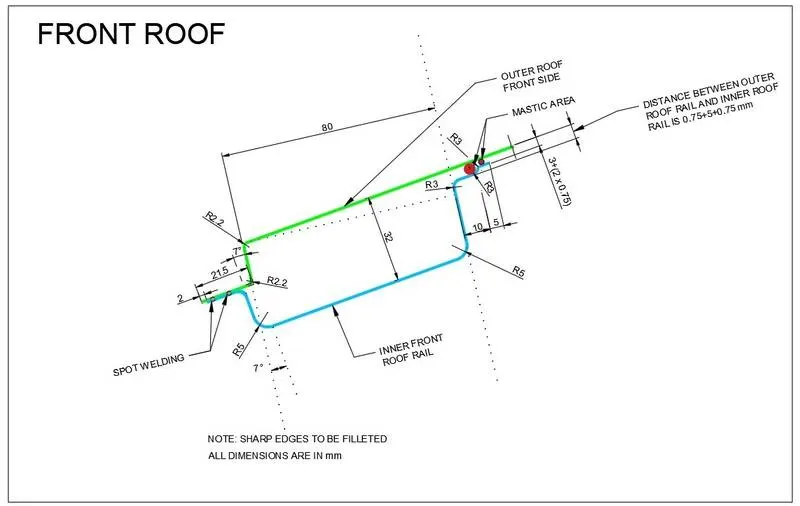
- Based on the master section, the front rail roof is designed with the non-dimensionated members assumed with appropriate dimensions
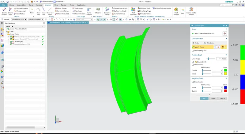
Draft Analysis: (w.r.t Y-axis)
Rear Rail Roof:
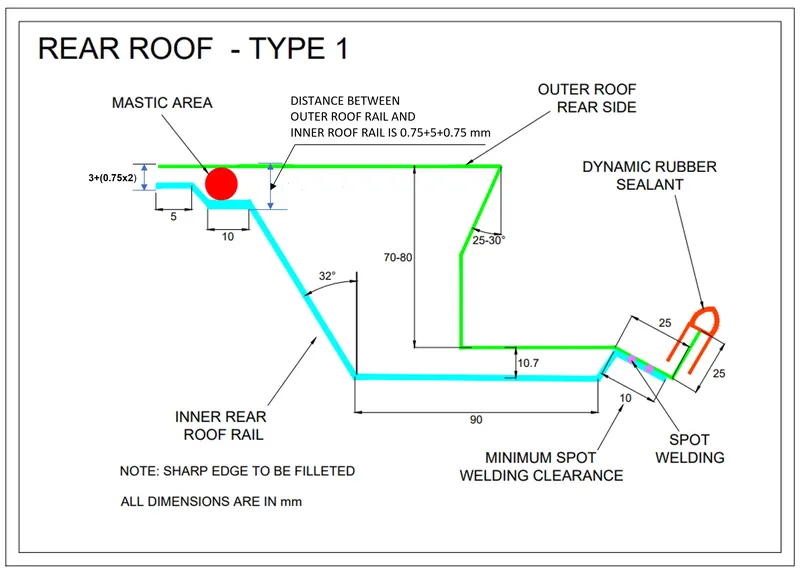
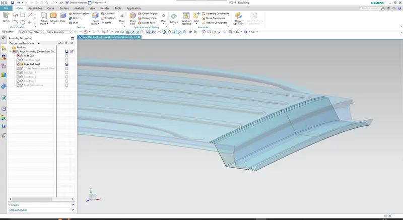
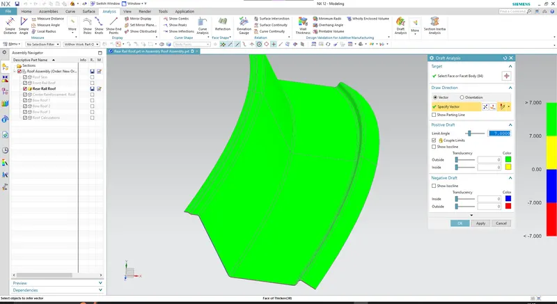
- The master section for this part differs from the front rail roof in that it has an element that its correspondent outer panel flange has negative draft w.r.t tooling axis (Y- major). This ensures the accomodation for the backdoor rotation about its hinge.
Draft Analysis:
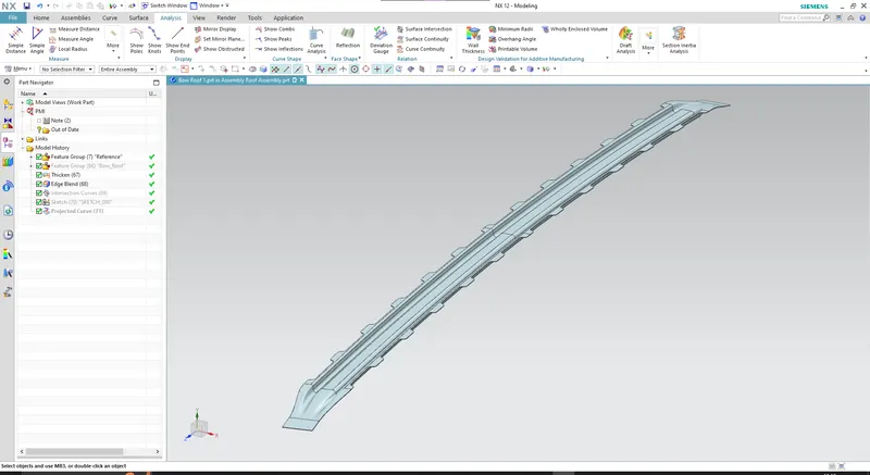
Bow Roof :
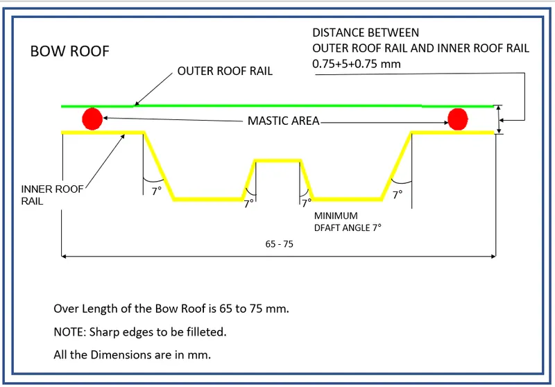
#1
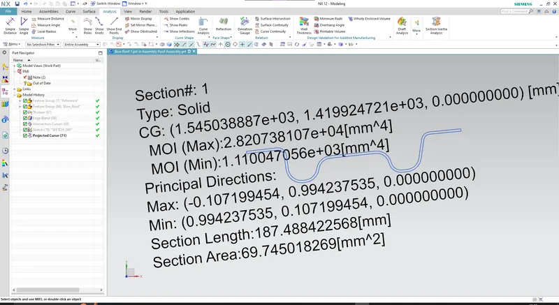
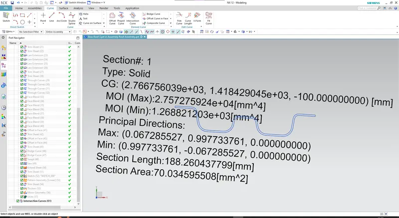
Section inertia analysis
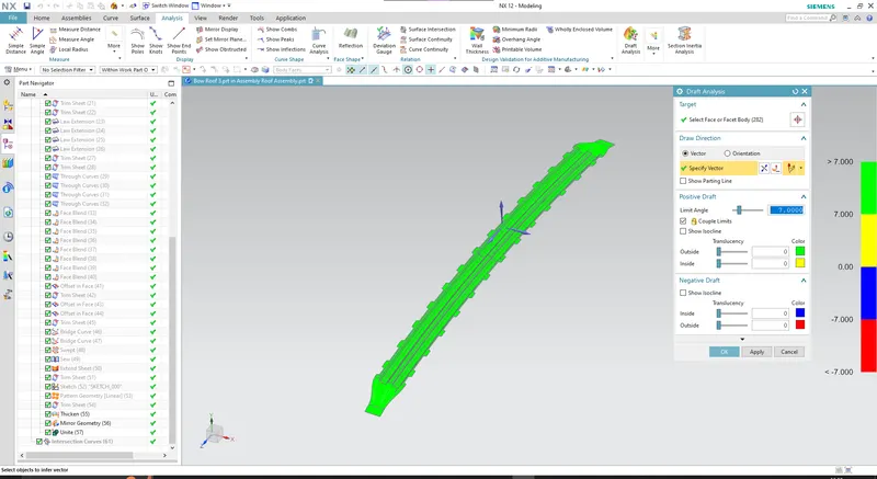
Draft Analysis:
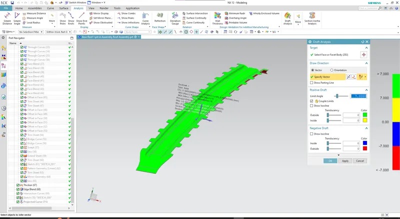
#2
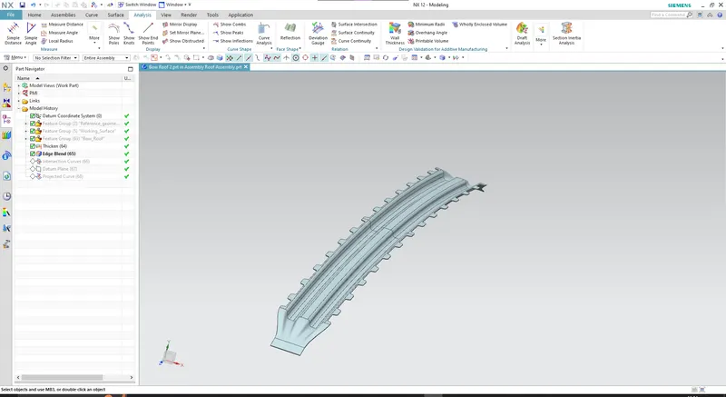
Section inertia analysis
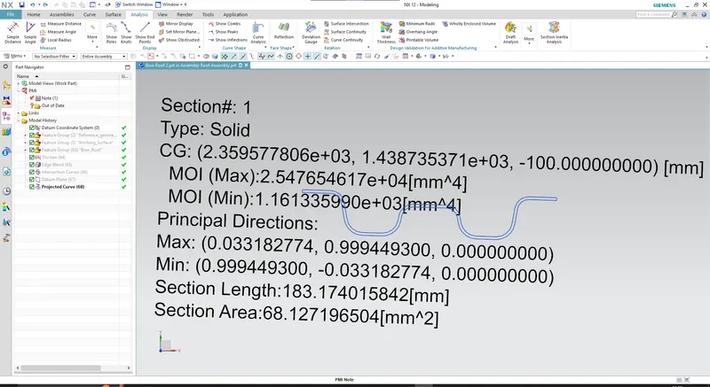
Draft analysis
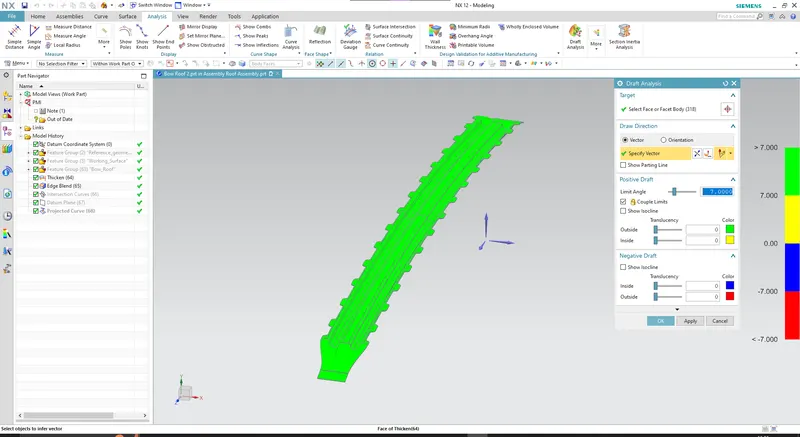
#3
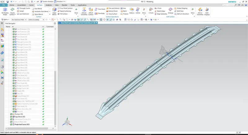
Section inertia analysis:
Draft Analysis:
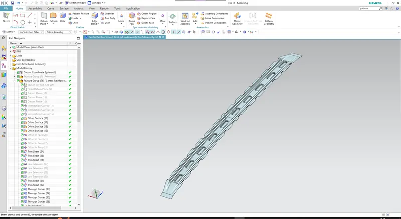
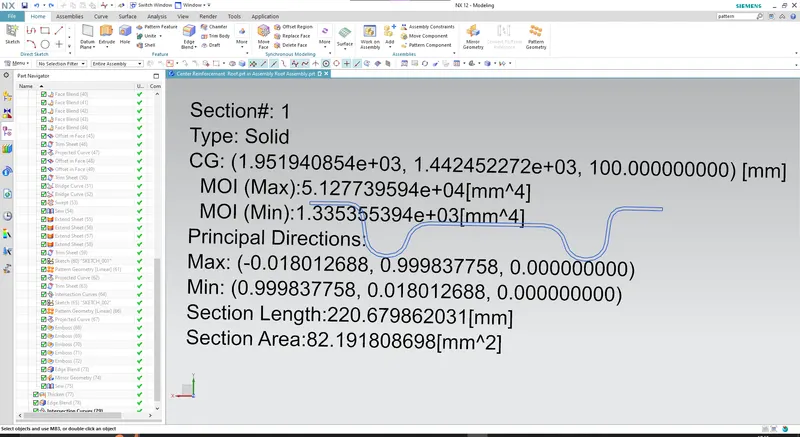
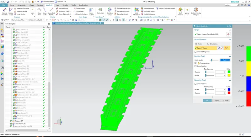
Center Reinforcement Rail:
Section inertia analysis:
Draft Analysis:
Heat Distortion Criteria:
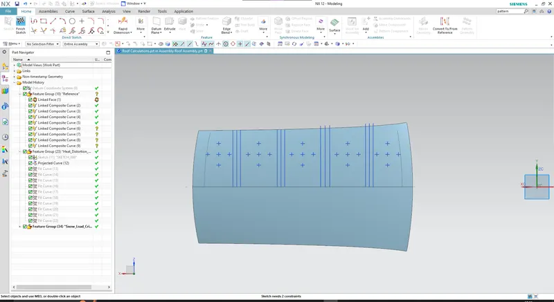
Heat distortion refers to the temperature threshold at which metal undergoes softening and deformation when subjected to a specific load. The purpose of this study is to evaluate the roof's capacity to withstand elevated temperatures while considering the placement of reinforcements, which significantly enhances its strength.
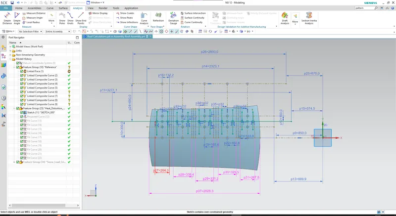
W = [1.73 x 10^(-3) x L] + [1.85 x 10^(-8) x (R^2)/t] + [ 1.10x10^(-3) x l] - 2.68
Where,
L = Roof Length in X-Direction[mm](Roof dimension in 0-Y)
R = Roof curvature
R = 2(Rx*Ry)/(Rx+Ry)
Rx = X curvature
Ry = Y curvature
t = Roof plate thickness [mm]
l = Bow Roof Span [mm]
Judgment Condition
OK< 2.7

Snow Load Criteria:
The Snow Load Criteria study aims to assess the roof's ability to withstand the weight of snow accumulation during winter in regions prone to snowfall. Additionally, this study examines whether the roof experiences any permanent deformation after the removal of the snow load, ensuring that it may bend under the weight but should have the capability to return to its original position.
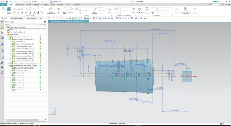
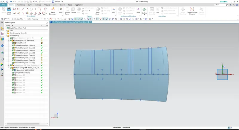
Qr = [Iy x t2] / [α x s x [(Rx + Ry)/2]2 x 10-8]
Note: The Qr value given over here is correct. There was a typo error in the formula given in the video.
Where,
α = My x Lx2 x 10-12 , My = Y(Ly-Y)
t = Roof plate thickness [mm]
Ly = Distance between the front and rear roof Rails on the Vehicle along with 0Y[mm]
Length of Roof panel with the center point between Roof rail Front /Rear as the front and rear reference point.
Lx = Distance between the Left and Right end of the roof on the Roof BOW [mm]
The width of the roof panel is exposed on the surface.
Y = Distance front Front Roof Rail to Roof BOW[mm]
s = Distance for which Roof BOW bears divided load [mm]
s = L1/2 + L2/2
Iy = Geometrical moment of inertia of Roof BOW (Y cross-section )[mm4]
Rx = Lateral direction curvature radius of roof panel Y cross-section on Roof BOW [mm]
Roof panel curvature Radius of the Length Lx in Front view
Ry = Longitudinal Direction curvature radius of the Roof panel X cross-section on Roof BOW [mm]
Roof panel X curvature radius of length s in Side view
Judgment condition
Qr ≥ 3.1 (primary)
250 ≤ s ≤ 380
